


CHINA J-VALVES Offers Various High-quality I ndustrial Ball Valves
J-VALVES, a distinguished professional ball valve manufacturer rooted in China, takes pride in its extensive product portfolio. Our offerings span a wide range, including trunnion-mounted ball valves, floating ball valves, high-temperature ball valves, high-pressure ball valves, metal-sealed ball valves, ultra-low temperature ball valves, DBB ball valves, Three-way And Four-way Ball Valve, and fully welded ball valves. Each product is a testament to our commitment to precision engineering and reliable performance. Meticulously crafted, they are designed to not only meet but exceed the most stringent industrial demands, ensuring stable operation even under extreme conditions. This enables us to provide our clients with high-value services and makes our valves widely sought-after in industries.
Product Category
Contact Us

-
J-VALVES-Q367F
-
J-VALVES
Overview of the J-VALVES underground fully welded ball valve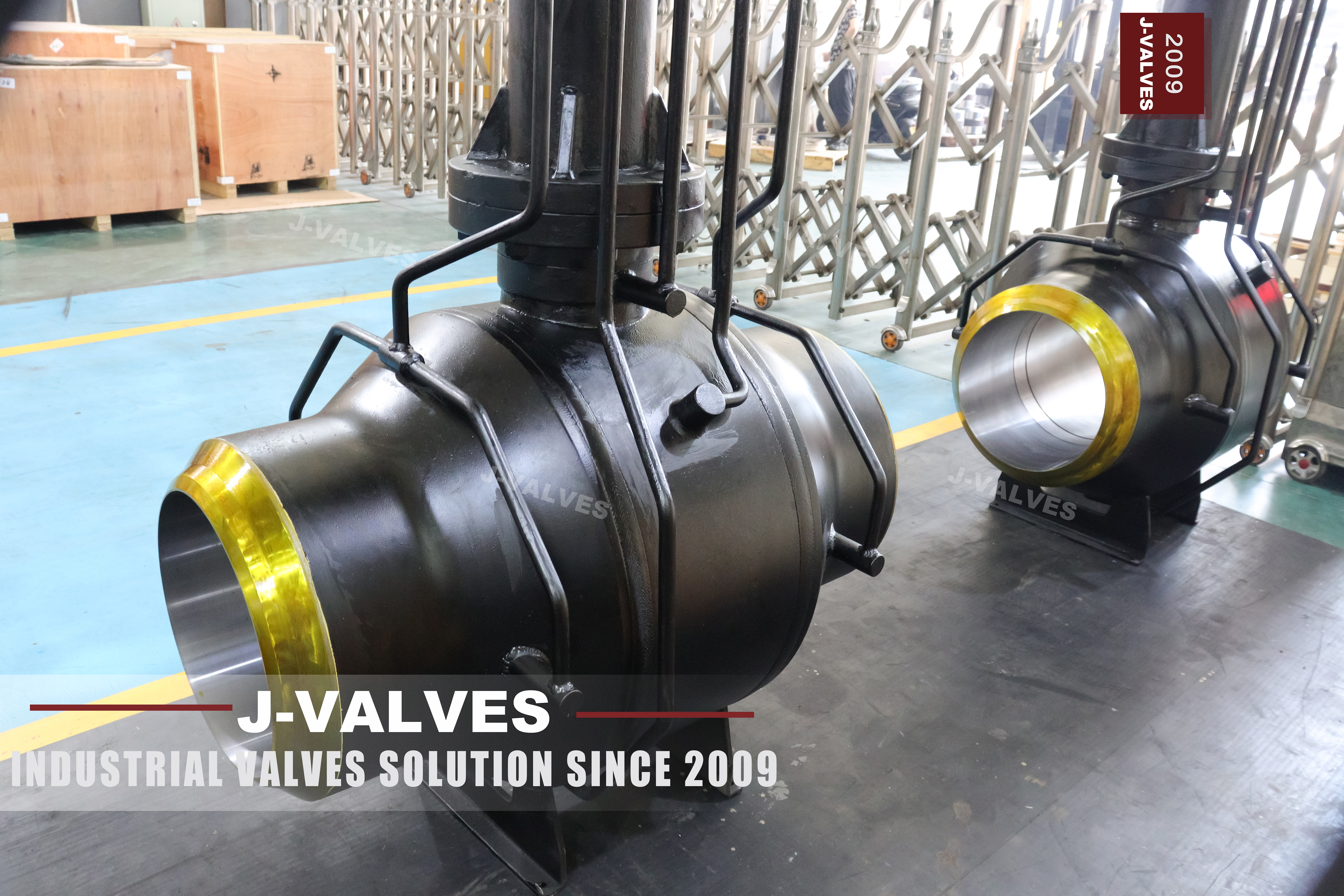
This page has a more complete specification than most: size range, class range, temperature, body and its alternatives, ball, trunnion, stem, extension sleeve, seat, packing, welding consumables, ends, stem extension length, external coating, cathodic protection compatibility, operation, design standard, test standard and face to face. Almost every line a buyer would ask for is already there.
What is not there is the ground. Nothing on the page tells you how deep the valve will be buried, what the soil does to steel, how the field joints will be coated, or how many anodes the coating will need. Those four numbers decide the coating, the cathodic protection and the extension length, and all four come from a survey rather than from a catalogue. A specification that is complete about the valve and silent about the ground has stopped one step short of being orderable.
There is a second gap, and it is a consequence of a claim. The page says the valve can be buried without a pit or a waterproof seal, which is true for the body and true for the operator, because the stem comes up to ground level. It is not true for the drain or for the seat injection ports, which stay on the body. A valve with no pit has two fittings nobody can reach.
This page is about those two gaps. It takes the table as good, and follows what has to be added to it before a six to fifty six inch welded valve can be buried and then maintained.
Design and Construction
The shell is welded from a forged pipe section and two forged ends, with no body flange and no bolted joint, and the ends are prepared for butt welding to the pipe. The ball runs on an upper and a lower trunnion, so the pressure load goes into the bearings and the seats only seal. The stem leaves the body through graphite packing and runs up inside a coated sleeve to an operator above ground.
The three openings that are not welds are the stem, the drain and the seat injection ports. On an above ground valve all three are reachable and all three are on a maintenance route. Buried, only the stem reaches the surface, and the other two are behind a coating and under backfill, which is the subject of the second half of this page.
The seating arrangement is the standard three: double piston effect, single piston effect, or a combination. The choice matters more on a buried valve than on an above ground one, because on a double piston build the cavity has no route out at all and the drain is the only manual relief. A valve that cannot be reached should not be the one that depends on somebody opening a plug.

Three Rows the Table Is Missing
The table stops at the valve. Three rows belong beside it, and none of them can be filled in by the maker, because all three are properties of the place the valve is going rather than of the valve.
| Missing Row | Who Supplies It | What It Changes |
|---|---|---|
| Burial depth to the top of the pipe | The civil design | The stem extension length and the pit or kerb box |
| Soil resistivity and chemistry | A site survey, measured not assumed | The coating class and the cathodic protection design |
| Field joint method and test | The pipeline specification | The sleeve or tape, the holiday test, the joint register |
| Anode type, quantity and design life | The CP design, from the survey | Whether the protection outlasts the valve |
| Backfill and bedding specification | The civil design | Whether the coating survives being buried at all |
| Access to the drain and the ports | A decision, not a drawing | Whether the valve can be bled without excavation |
The soil row is the one that is most often assumed. A coated steel structure in soil is protected by two things working together: the coating keeps most of the current off the steel, and the anodes supply current where the coating is missing. How much current is needed depends on the soil, and soil resistivity varies by orders of magnitude between a gravel bed and a clay trench. The same valve and the same coating can be adequately protected in one and under protected in the other, and the table cannot tell the difference.
The field joint row is the second. A factory coated valve arrives with bare ends, because the ends are welded on site and welding burns coating. Each of those joints is coated afterwards, by hand, in a trench, and tested afterwards, by hand, in a trench. There are two of them per valve and they are the only part of the coating that is not made under factory conditions. A specification that names a factory coating standard and stops there has described the easy part.
The access row is the one that follows from the no pit claim. A valve buried without a pit has its operator at ground level and its body two metres down, which is exactly what the design intends for operation and exactly what it prevents for maintenance. The drain and the injection ports are at the body. If they are to be usable, the design needs either a small access chamber at the valve, or the ports extended to the surface, or an acceptance that the cavity will never be bled.
Technical Specifications
The table is the build as the page states it, with the three missing rows marked as coming from elsewhere rather than quietly omitted. The class range on the page starts at PN 16, which is a flange rating rather than a valve class, and is corrected here.
| Item | Value |
|---|---|
| Size range | 6 inch to 56 inch, DN 150 to DN 1400 |
| Pressure class | Class 150 to Class 2500, PN 20 to PN 420 |
| Temperature | Minus 29 to plus 425 Celsius, per the seat fitted |
| Body | ASTM A105, or A350 LF2 to minus 46, A694 F52 and F65, A182 F316 |
| Ball | A105 with ENP or carbide coating, or solid F316 |
| Trunnion | Surface hardened A105 or 17-4PH |
| Stem | 17-4PH or nickel alloy 718, extended |
| Extension Sleeve | A105 or F316, coated, with 3PE or FBE |
| Stem Extension | 500 to 2000 mm, or to the burial depth |
| Seat | PTFE or RPTFE, PEEK, or metal with graphite |
| Ends | Butt weld to ASME B16.25, matched to the pipe |
| External Coating | 3PE, FBE or coal tar epoxy, as specified |
| Cathodic Protection | Sacrificial anodes or impressed current, by design |
| Burial Depth | From the civil design, not from this table |
| Field Joint | From the pipeline specification, with a holiday test |
| Design and Test | API 6D and ASME B16.34, tested to API 6D and API 598 |
The two rows at the bottom are the ones the page cannot answer, and they are also the two that decide the cost of the installation. A short extension and no chamber is the cheapest arrangement to build and the most expensive to maintain. A chamber at every valve is the opposite. The choice is a maintenance philosophy, and it should be made by the operator rather than by whoever draws the trench.
Standards and Compliance
API 6D governs the valve, ASME B16.34 the wall and the ratings, and ASME B16.25 the weld end profile. The coating and the cathodic protection are covered by pipeline documents rather than valve documents, and the civil work by neither. That separation is the reason a valve can be perfectly compliant and still be buried in a way that destroys it.
| Document | What It Fixes | What It Does Not Cover |
|---|---|---|
| API 6D | Classes, test, marking, cavity relief | Coating, CP and burial |
| ASME B16.34 | Wall, material groups, ratings | The installation |
| ASME B16.25 | Weld end profile | The field joint coating |
| DIN 30670 | Factory applied PE coating and its tests | The joint made in the trench |
| DIN 30672 | Field joint tapes and sleeves | The factory coating |
| DIN 30675 | Corrosion protection of buried pipelines as a system | The valve specifically |
| AWWA C213 | Factory applied FBE for water pipelines | Gas pipeline practice |
The system document is the one worth knowing about, because it is the only one on that list that treats coating and cathodic protection as one design rather than two purchases. A coating decision made without the CP design is half a decision, and the half that is missing is the one that fails quietly: an under protected valve does not leak, it pits, and the pit is found when the valve is excavated for another reason.
Manufacturing Process
The body is welded, radiographed, machined and tested, and the coating is applied after every machining operation and every weld. The order is not negotiable: any welding after coating destroys the coating locally, and a local repair in a plant is a different product from a factory applied layer.
The ends are masked before coating, and the length of the mask is the cut back. It has to be long enough for the field weld and the heat it puts into the pipe, and short enough that the field joint sleeve can reach sound factory coating at both ends. That number comes from the welding procedure and the sleeve, not from the valve drawing, which is why it is agreed rather than assumed.
The extension sleeve is made and coated as a separate assembly, and it is fitted after the stem has been proved to turn freely. A sleeve that is fitted over a stiff stem hides the stiffness until commissioning, when the valve is buried and the operator is at the surface.
The top flange deserves its own operation. It carries the operator, it is the interface that has to stay square to a shaft two metres below it, and it is the only part of the buried assembly that somebody will handle when the gearbox is fitted. A flange that is welded and then faced in place is square; one that is welded and left is not, and the error is invisible until the operator is bolted down and the shaft starts to bind on its guides.

Quality Control and Testing
Pressure testing comes before coating: a shell test and a seat test to API 6D and API 598, with the coating applied after the last weld and the last machining cut. The coating test is a separate set: holiday detection over the whole surface, thickness, adhesion, and a cathodic disbondment check where the specification asks for it. Those are the tests the factory coating standard defines, and they are recorded against the coating.
The extension is checked for free rotation and for guide friction before it is buried, and the top connection is checked for squareness to the shaft. That check is worth more than it looks: a shaft that binds in its sleeve is found at commissioning with the valve already in the ground, and the remedy is an excavation.
The field joint has no record at the works because it does not exist yet. What can be done is to supply the joint material to the same specification as the pipe, write the holiday test into the installation procedure, and require a joint register with a test result against each joint. Without that register the coating has an unknown number of holes in it and nobody knows where.

Applications and Industry Service
Buried transmission and distribution lines are the first use, where the valve is a section isolator and the operator is at the surface. Six to fifty six inch covers the branch isolator and the mainline valve, and the same table applies to both.
The second use is a crossing, where the valve has to be under a river, a road or a rail line and the operator has to be above it. Those are the places where the depth is greatest, the extension longest and the excavation most expensive, which is exactly where the access question should be settled before the design is frozen.
The valve is the wrong choice where nobody will ever excavate, because a valve that cannot be bled or injected is a valve that is maintained only by hope. It is also the wrong choice where the soil survey has not been done, because the coating and the CP design both depend on it and neither can be corrected after backfill.

Installation, Operation and Maintenance
Installation starts with the survey and the bedding. The trench, the bedding material and the groundwater decide whether the coating survives being lowered in, and a coated body set down on rock has holidays before the first weld. The valve is aligned, welded, tested, and the field joints are coated and holiday tested before backfill.
Operation is at the top of the stem, which is the one part of the valve that was designed to be reached. The drain and the injection ports are the two that were not, and the operating procedure should say what happens to them: whether they are extended to the surface, reached through a chamber, or accepted as unreachable. Any of those is a decision. None of them is what happens by default.
Maintenance is the operator, the packing at the top, the coating inspection where it is exposed at the pit, and the cathodic protection readings at the test posts. The body has no maintenance operation that can be performed without excavation, which is why the survey, the coating and the CP design carry the whole of the reliability of this valve.
How to Specify and Order
The order lines below are the ones the page leaves open, and the first four are the ones that decide whether the valve is protected and reachable rather than merely buried.
| Line on the Order | What to Write | Why It Matters |
|---|---|---|
| Burial depth | Depth to the top of the pipe, and the extension that follows | It sets the stem length and the pit |
| Soil survey | Resistivity and chemistry, measured at the route | The coating class and the CP design follow from it |
| Field joint | Sleeve or tape, standard, and holiday test | Two per valve, made by hand in a trench |
| Anode design | Type, quantity and design life | The anodes will not outlast the valve by default |
| Access to ports | Chamber, extended ports, or a written acceptance | The drain and the injection ports are at the body |
| Seat arrangement | Single or double piston effect, per seat | A double piston cavity needs a relief route |
| Class | Class 150 to API 6D, not PN 16 | PN 16 is a flange rating, not a class |
| Ends | Weld end profile and the pipe grade it joins | The field weld is made to both |
Read as a whole, the page describes a valve whose specification is unusually complete about the object and completely silent about the place. The welded shell, the trunnion, the coating and the extension are all stated. What is missing is the depth, the soil, the joint and the way in, and those four are what decide whether the valve is still operable and still protected when somebody finally needs it.
FAQ
Q: The table looks complete. What is actually missing from it?
A: The ground. Burial depth, soil resistivity and chemistry, the field joint method and its test, the anode design, and the backfill specification. None of those can come from the maker, and all of them change the coating, the cathodic protection and the stem length.
Q: Why does soil resistivity change the valve specification?
A: Because coating and cathodic protection are one system. The coating keeps most of the current off the steel and the anodes supply current where the coating is missing. How much current is needed depends on the soil, and resistivity varies by orders of magnitude between one route and another, so the same valve and coating can be well protected in one place and under protected in another.
Q: If the valve needs no pit, how is the drain reached?
A: It is not, and that is the point. The stem comes to the surface and the drain and injection ports stay at the body, two metres down. A no pit design is a decision to give up access to those two fittings unless a small chamber or an extended port is added, and that decision should be written down rather than discovered.
Q: How many field joints does one buried valve have?
A: Two, one at each end, and each is coated by hand in a trench and holiday tested after coating. They are the only part of the coating not made under factory conditions, and they are the part most likely to be under tested because the test equipment has to be on site.
Q: Do the anodes last as long as the valve?
A: Not by default. A sacrificial anode has a design life that is chosen in the CP design, and the valve is quoted at decades. The anode design, the test posts and the possibility of re-anoding are part of the same decision as the burial depth, and leaving them out is how a protected valve becomes an unprotected one.


Hot Products


News
Urea Plant Ball Valves: The Wetted Path Survives Only While Oxygen Is Being Fed To It
Carbamate at 150 bar and 185 C eats stainless 50 times faster once the passive film starves. The valve cavity is where the oxygen runs out first.
Read More
Stiction: What A Ball Valve Becomes When Nobody Turns It
A valve that stood closed for years has not worn out. The seat has bonded to the ball, and the first stroke is a step, not a ramp. What the trace shows.
Read More
Molten Salt Ball Valves: The Valve Works at 565 C And Dies at 219 C
Salt freezes at 220 C and decomposes at 565 C. Everything a molten salt ball valve does happens in that 345 kelvin gap, and the gap is not generous.
Read More
Direct Air Capture Ball Valves The Vacuum Side Runs The Seal Backwards, And Three Hundred Thousand Strokes Decide The Design
A solid sorbent DAC plant moves 1.3 million cubic metres of air per tonne of CO2, then asks a DN50 ball valve to hold 0.9 bar from the wrong side.
Read More