


CHINA J-VALVES Offers Various High-quality I ndustrial Ball Valves
J-VALVES, a distinguished professional ball valve manufacturer rooted in China, takes pride in its extensive product portfolio. Our offerings span a wide range, including trunnion-mounted ball valves, floating ball valves, high-temperature ball valves, high-pressure ball valves, metal-sealed ball valves, ultra-low temperature ball valves, DBB ball valves, Three-way And Four-way Ball Valve, and fully welded ball valves. Each product is a testament to our commitment to precision engineering and reliable performance. Meticulously crafted, they are designed to not only meet but exceed the most stringent industrial demands, ensuring stable operation even under extreme conditions. This enables us to provide our clients with high-value services and makes our valves widely sought-after in industries.
Product Category
Contact Us

-
J-VALVES-Q367F
Overview of the J-VALVES underground trunnion mounted fully welded ball valve
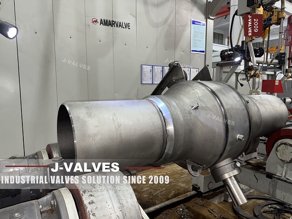
A buried valve is operated from above ground, and the only connection between the handle at the top and the ball at the bottom is a shaft. The page describes that shaft as an extended stem, sized to the burial depth, with a length that runs from five hundred millimetres to three thousand. That reads like a civil dimension, as if the depth of the trench decided it.
The depth decides how much shaft is needed. It does not decide how much shaft can be used. A stem is a torsion bar: it transmits torque by twisting, and the twist it needs grows with its length and falls away very steeply as its diameter grows. At three metres the same torque that turns a ball at the bottom also winds the shaft up, so the top of the stem rotates through an angle before the ball moves at all, and the position indicated at the top is not the position of the ball.
This page is about that shaft. It is a two to fifty six inch welded trunnion valve with a stem extended into a sleeve and an operator above ground, and the rest of it is the settled construction this family uses everywhere. What is not settled is how the extension is supported, what its length limit actually is, and what a settlement joint at the top can and cannot absorb.
Design and Construction
The body is closed by welding rather than by bolting: a pipe section with a forged end at each side, and no joint across the shell. The ball runs on an upper and a lower trunnion, so the pressure load goes into the bearing system and the seats only seal. The stem leaves the body through graphite packing, held by a shoulder below it, and continues upward inside a sleeve to the operator.
The seal stays in the body. That is the important structural point about the extension and the page makes it in a different section: the stem seals are in the body, so a seal failure does not travel up the sleeve as a leak at the operator, and the extension is not affected by it. What the sleeve does is keep groundwater and soil away from the packing, which is a different job from sealing.
The top of the stem is described as a standardised connection, compatible with pits, extension sleeves and the usual actuators, so that manual, pneumatic, electric and hydraulic operation are all available at ground level. That is a real convenience and it is also where the settlement joint lives, which is the part that needs the most careful reading.

The Extension as a Torsion Bar
The honest way to think about a three metre stem is as a spring in series with the valve. Torque applied at the top is stored as twist before it reaches the ball, and the amount stored depends on the length, the diameter, the material and the temperature. Nothing about the ball changes; the operator simply has to turn further for the same result.
| What Sets the Limit | Why It Bites at Long Extensions | What Can Be Done |
|---|---|---|
| Torsional wind up | The top turns before the ball does, and the lag grows with length | Larger stem, or an intermediate bearing and a shorter unsupported span |
| Lateral stiffness | A long slender shaft in a sleeve can whip or rub when driven hard | Intermediate guide bushes inside the sleeve |
| Operator weight | The drive sits on top of the shaft and loads it in compression | A load bearing top plate rather than the stem |
| Bearing friction | Each guide adds drag, and drag adds to the torque at the top | Fewer, better guides rather than more of them |
| Settlement joint backlash | A universal joint transfers torque with lost motion | A joint sized for the torque, not for the shaft diameter |
| Ground movement | Angular movement is absorbed, axial movement is not | A separate expansion element where axial movement is expected |
That table is why this page and its neighbour should not both be taken at face value. One page in this family quotes a maximum extension of two thousand millimetres and this one quotes three thousand, for what is described as the same welded trunnion valve with the same top connection. One of those numbers is a standard, and the other is a limit that depends on the stem diameter and the number of guides. The figure that belongs on the drawing is not a length; it is a length with the shaft size and the guide spacing that make it work.
The settlement joint deserves its own paragraph because it is often specified as if it solved every ground movement problem. A universal joint absorbs angular misalignment between the top of the stem and the operator, which is what happens when the ground settles at one side of a pit. It does not absorb axial movement, and it does not absorb a change in the distance between the valve and the operator. Where the ground can drop, the part that accommodates it is an expansion element in the shaft, and that is a different device from a universal joint.
The operator's position indicator is the last consequence. On a long stem the indicator is driven from the top of the shaft, not from the ball, so it shows where the top of the stem is rather than where the ball is. On a short extension the difference is nothing. On a three metre extension with a small stem, a valve that is reported as closed may still be a few degrees short, and the evidence is a seat that weeps rather than a switch that fails.
Technical Specifications
The table is the build as the page states it, with the extension written as a shaft rather than as a dimension. The class range on the page starts at PN 16, which is not a row in the valve class table and is corrected here.
| Item | Value |
|---|---|
| Size range | 2 inch to 56 inch, DN 50 to DN 1400 |
| Pressure class | Class 150 to Class 2500, PN 20 to PN 420 |
| Temperature | Minus 29 to plus 425 Celsius, per the seat fitted |
| Body | Forged A105, or A350 LF2, A694 F52 and F65, A182 F304, F316, F51 |
| Ball | Matching the body, chrome plated or nitrided |
| Trunnion | On bearing shafts, 440C or a lined type |
| Stem | 17-4PH, 316 or F51, extended |
| Stem Seal | Graphite packing in the body, not in the sleeve |
| Extension | 500 to 3000 mm, with the stem size and guide spacing stated |
| Top Connection | Standardised, for pit, gear, or actuator |
| Settlement Joint | Universal joint for angular movement only |
| Seat | Double piston effect as standard, single piston on request |
| Ends | Butt weld to ASME B16.25 or EN 12627 |
| Coating | Three layer polyethylene or fusion bonded epoxy |
| Design and Test | API 6D and ASME B16.34, tested to API 6D |
Two rows of that table carry the argument. The extension row is not a length but a length plus a shaft size plus a guide spacing, because any two of those without the third is a guess. And the settlement joint row says angular, because that is the only movement a universal joint absorbs; anyone who expects it to take up a settling pipe is expecting the stem to act as a spring in compression.
Standards and Compliance
API 6D governs the valve and ASME B16.34 the wall and ratings, and neither of them says anything about an extension three metres long. The extension is a piece of mechanical design that the standards leave to the drawing, which is why its limits are usually stated by the maker rather than found in a document.
| Document | What It Fixes | What It Does Not Cover |
|---|---|---|
| API 6D | Classes, test, marking, cavity relief | The stem extension |
| ASME B16.34 | Wall, material groups, ratings | The drive train above the stem |
| ASME B16.25 | Weld end profile | The European profile |
| EN 12627 | European weld end profile | The US profile |
| API 598 | Shell and seat test | The torque at the top of a long stem |
| ISO 5211 | Mounting pad and coupling at the operator | The shaft between pad and ball |
The mounting pad standard is worth one sentence because it is the interface that makes the whole arrangement possible. A pad to a recognised pattern means the operator can be changed without changing the valve, which is what allows a buried valve to be manual at installation and actuated later. It says nothing about the shaft below it, and the shaft is where the length limit lives.
Manufacturing Process
The body is welded, radiographed, machined and tested, and the extension is made as a separate assembly: a stem section, a coupling to the valve stem, guide bushes inside a sleeve, and a top flange that carries the operator. The coupling is the part that has to be right, because it is where the torque crosses from one piece to another and where a key or a spline either fits or does not.
The stem sections are straightened and, where the length requires it, stress relieved. A shaft that is not straight rubs in its guides, and a rubbed guide adds friction that the operator has to overcome on every stroke. The guides are spaced so the unsupported span is short enough that the shaft cannot whip when the valve breaks away, which is the moment of highest torque and the moment of least stability.
The sleeve is fitted after the shaft is proved to turn freely, and the top flange is aligned to the operator so the pad is square to the shaft. On a buried valve the sleeve is also the corrosion barrier for everything inside it, and its coating is applied with the same care as the body coating rather than as an afterthought.

Quality Control and Testing
The valve test is the shell and seat test to API 6D and API 598, done before the extension is fitted. The extension test is different: the shaft is turned through the full quarter at the operating torque and the free rotation is checked at both ends, the guide friction is measured, and the top connection is checked for squareness to the shaft.
The setting is done with the extension in place, because the position of the operator is decided by the position of the ball plus the wind up of the shaft. A valve that is set on the bench with a short stub and then fitted with a three metre extension arrives with its stops in the wrong place, and the error is in the direction that leaves the valve slightly open.
The coating and the sleeve are checked before dispatch, and the top of the sleeve is sealed so that the inside stays dry in transit. Water inside a sleeve during shipping is the most common way a stem is found stiff at commissioning, and it is invisible from outside.

Applications and Industry Service
Buried transmission lines are the first use, where the valve is a section isolator and the operator is a gear at the top of a stem in a pit. Two to fifty six inch covers the range from a branch isolation to a mainline valve, and the same extension logic applies to both.
The second use is a crossing, where the valve has to be below a river or a road and the operator has to be above it. Those are the cases where the extension is longest and where the settlement joint is specified, and they are also the cases where the length limit is most likely to be tested by a site that has already dug the hole.
The valve is the wrong choice where the extension would have to be longer than the shaft can carry without intermediate support, and where the ground is expected to move axially rather than angularly. It is also the wrong choice where the operator has to indicate position precisely, because the indicator follows the top of the stem and the top of a long stem lags the ball.

Installation, Operation and Maintenance
Installation begins with the pit and the alignment, not the valve. The valve is set on its bedding, the stem is aligned vertically to the operator, and the sleeve is fixed so that it does not load the stem. A sleeve that is bolted to a settling structure will pull the shaft sideways as the structure moves, which is a way of turning a settlement problem into a bent stem.
Operation is at the top, and the two readings worth taking are the turns required to move the valve and the torque at breakaway. A valve that needs more turns than it did at commissioning is winding up more, which points to a rubbing guide rather than to a stiff seat. A breakaway torque that climbs points the other way.
Maintenance is the operator, the packing at the top of the body and the coating on the sleeve. The extension itself has no service item beyond the guides, which are inside the sleeve and therefore only reachable if the sleeve is opened. That is an argument for laying the sleeve out so it can be opened, rather than welding it closed for neatness.
How to Specify and Order
The order lines below are the ones the page leaves open, and the first two are the ones that decide whether the extension works or merely fits.
| Line on the Order | What to Write | Why It Matters |
|---|---|---|
| Extension length and shaft size | The length, the stem diameter and the guide spacing | Length alone is not a specification |
| Settlement device | Universal joint for angular, expansion element for axial | The two absorb different movements |
| Top connection | Pad pattern, and the operator to be fitted | The pad allows a change of drive later |
| Operator weight | Stated, so the top plate carries it | A drive hung on the stem loads it in compression |
| Position indication | Whether the indicator must reflect the ball | On a long stem it reflects the top |
| Class | Class 150 to API 6D, not PN 16 | PN 16 is a flange rating, not a class |
| Weld ends | B16.25 or EN 12627, and what the pipe is cut to | The two profiles are not interchangeable |
| Coating | Body and sleeve, with the field joint standard | The sleeve is a corrosion barrier too |
Read as a whole, the page describes a valve that is separated from its operator by a shaft, and the shaft is the part with the least obvious limits. The welded shell and the trunnion are settled. What decides whether the valve opens on the day it is needed is whether the extension was specified as a torsion bar with a diameter and a guide spacing, or as a length taken from the depth of a trench.
FAQ
Q: What actually limits how long the stem extension can be?
A: Not the burial depth. The depth says how much shaft is needed; the limit comes from torsional wind up, lateral stiffness, guide friction and the weight of the operator on top. A long slender shaft twists before the ball moves and can rub or whip in its guides, so the length is always quoted with a shaft diameter and a guide spacing that make it work.
Q: Does a universal joint take up ground settlement?
A: Only the angular part of it. A universal joint absorbs misalignment between the top of the stem and the operator, which is what a pit settling on one side produces. It does not absorb the distance between the valve and the operator getting shorter, so a ground movement that is axial needs an expansion element in the shaft, not a joint.
Q: Why does the position indicator on a long stem mislead?
A: Because it is driven from the top of the shaft rather than from the ball. The shaft winds up under torque, so the top has to turn further than the ball does, and at the end of the stroke the difference is a few degrees. On a short extension that is nothing; on a three metre one it can be the difference between seated and nearly seated.
Q: Twin pages in this family quote different maximum extensions. Which is right?
A: Both can be, if they carry different shaft sizes and guide spacings. A maximum length on its own is not a specification, because the same length is easy with a larger stem and a closer guide spacing and hard with a small one. The drawing should state all three numbers.
Q: Where is the stem sealed, at the top or at the body?
A: At the body. The packing sits in the body below the sleeve, so a seal failure does not become a leak at the operator and the extension is not affected by it. The sleeve is there to keep groundwater and soil away from the packing, which is a different job from sealing.


Hot Products


News
Urea Plant Ball Valves: The Wetted Path Survives Only While Oxygen Is Being Fed To It
Carbamate at 150 bar and 185 C eats stainless 50 times faster once the passive film starves. The valve cavity is where the oxygen runs out first.
Read More
Stiction: What A Ball Valve Becomes When Nobody Turns It
A valve that stood closed for years has not worn out. The seat has bonded to the ball, and the first stroke is a step, not a ramp. What the trace shows.
Read More
Molten Salt Ball Valves: The Valve Works at 565 C And Dies at 219 C
Salt freezes at 220 C and decomposes at 565 C. Everything a molten salt ball valve does happens in that 345 kelvin gap, and the gap is not generous.
Read More
Direct Air Capture Ball Valves The Vacuum Side Runs The Seal Backwards, And Three Hundred Thousand Strokes Decide The Design
A solid sorbent DAC plant moves 1.3 million cubic metres of air per tonne of CO2, then asks a DN50 ball valve to hold 0.9 bar from the wrong side.
Read More