


CHINA J-VALVES Offers Various High-quality I ndustrial Ball Valves
J-VALVES, a distinguished professional ball valve manufacturer rooted in China, takes pride in its extensive product portfolio. Our offerings span a wide range, including trunnion-mounted ball valves, floating ball valves, high-temperature ball valves, high-pressure ball valves, metal-sealed ball valves, ultra-low temperature ball valves, DBB ball valves, Three-way And Four-way Ball Valve, and fully welded ball valves. Each product is a testament to our commitment to precision engineering and reliable performance. Meticulously crafted, they are designed to not only meet but exceed the most stringent industrial demands, ensuring stable operation even under extreme conditions. This enables us to provide our clients with high-value services and makes our valves widely sought-after in industries.
Product Category
Contact Us

-
J-VALVES-Q367F
Overview of the J-VALVES 12x10 A105 hydraulic three piece flanged ball valve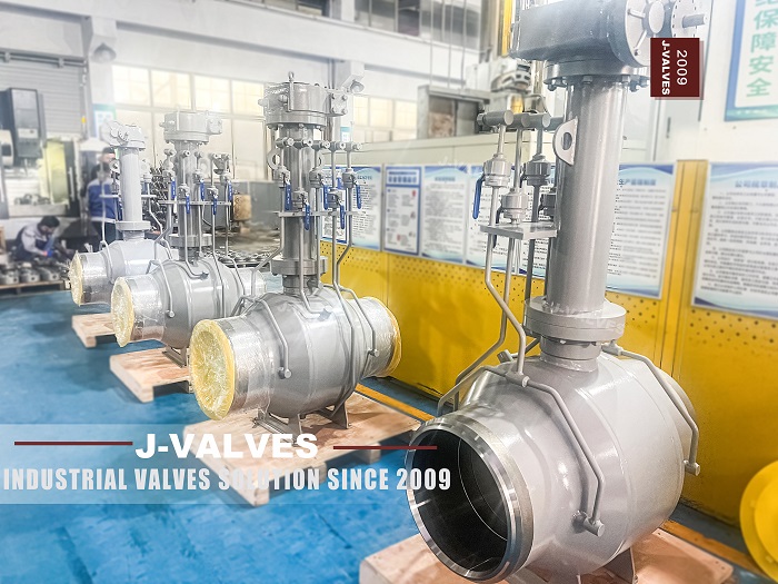
Two numbers are printed on this valve and they belong to two different sets of drawings. The twelve is the end: the flange that is bolted to the pipe, the bolt circle that has to line up with it, and the face to face length that the piping is laid out for. The ten is the bore: the hole the medium passes through, and the only number that has anything to say about flow. A page that reads 12x10 as one size will get the flange right and the bore wrong, or the other way round.
The page does state the difference, in a reduced bore paragraph that is correct as far as it goes. What it does not do is follow the difference through the rest of the specification. The face to face line still says ASME B16.10 without saying which size is looked up in it, the end connection says ASME B16.5 without saying which nominal size the flange belongs to, and the size range says Class 150 to Class 2500 while the seat column offers three polymers.
This page follows the two numbers separately. What the twelve decides, what the ten decides, where the two meet, and which of them is the one the piping designer has to be told about before the line is drawn rather than after.
Design and Construction
The body is three pieces of forged A105, normalized: a left body, a right body and a centre section. The centre section carries the ball and both seats, and the two outer pieces carry the flanges. That split is what makes a 12x10 valve practical, because the centre section is where the reduced bore is created and the two ends are standard flanged pieces.
The reduction is made in the centre section, not in the ends. The bore through each end piece is already smaller than the flange it is cast around, and the ball has a ten inch passage through it. That is why a reduced bore valve costs less than a full bore one of the same size: the ball, the seats and the centre section are all sized for the smaller bore, while the ends stay at the size the pipe needs.
The ball is described on the page as floating, and the feature block on the same page says trunnion mounted. Only one of those can be true, and at twelve inch it is the trunnion. A ball of that diameter carrying the seat load of a high class valve cannot be held by the seats alone; it is carried on an upper and a lower shaft, and the seats only have to seal against it. The consequence is worth stating because it changes the whole maintenance picture: the seats are not carrying the ball, so seat wear is a sealing problem rather than a support problem.
The stem is 410 or 420 stainless, or 17-4PH. That choice is made by the torque and by the medium rather than by the class, and on a hydraulic unit the torque is applied quickly, so the stem sees its peak load at the start of the stroke rather than gradually.

Reduced Bore, Two Sizes
The useful way to hold 12x10 in mind is as two columns of decisions that never mix. Everything about the joint to the pipe comes from the twelve. Everything about the flow comes from the ten. The only place they meet is the reducer inside the body.
| What Is Being Decided | Which Number Decides It | Where It Is Looked Up |
|---|---|---|
| Flange size and bolt circle | 12 inch, DN 300 | ASME B16.5, at the class ordered |
| Face to face length | 12 inch, DN 300 | ASME B16.10, flanged valve table |
| Gasket and stud set | 12 inch, DN 300 | The flange standard, at the class |
| Bore and flow area | 10 inch, DN 250 | The valve drawing |
| Pig passage | 10 inch, DN 250 | The pig specification |
| Ball, seats and centre section | 10 inch, DN 250 | The valve drawing |
| Actuator torque | 10 inch bore at the class | Measured, not looked up |
That table is the whole argument of the page, and it has one practical consequence that is easy to miss. A 12x10 valve belongs in a twelve inch line. It is bought to save weight, height and cost on a twelve inch run, not to adapt a twelve inch valve to a ten inch pipe. Put one in a ten inch line and two reducers are needed, one at each end, which is exactly the weight and the welded joints the reduced bore was supposed to avoid.
The other consequence is the pressure drop, and it is a real one at this ratio. A ten inch bore inside a twelve inch line accelerates the flow at the valve and then decelerates it, and the loss is permanent rather than recoverable. On a line where the valve is open all year and the throughput matters, that loss is a running cost. On a line where the valve is normally closed and opened for isolation, it is nothing.
Technical Specifications
The table below separates what the page states from what has to be looked up. Nothing in it is a conversion: the class is written as the class and the ends are written by the size they are.
| Item | Value |
|---|---|
| Nominal bore | 12 inch by 10 inch, DN 300 by DN 250 |
| Pressure class | Class 150 to Class 2500, PN 20 to PN 420 |
| Temperature | Minus 29 to plus 425 Celsius |
| Body | ASTM A105 forged carbon steel, normalized, three pieces |
| Ball | A105 with hard chrome, or 304 or 316 stainless |
| Stem | 410 or 420 stainless, or 17-4PH |
| Seat | PTFE, RPTFE or PPL, to be named on the order |
| Packing | Flexible graphite |
| Ends | Raised face flange to ASME B16.5, twelve inch |
| Face to face | ASME B16.10, looked up at twelve inch |
| Actuation | Hydraulic, double acting or spring return |
| Supply | 10 to 21 MPa hydraulic |
| Design | ASME B16.34, and API 608 only to Class 600 |
| Test | API 598 |
The seat row and the class row do not sit comfortably together. The class column promises 2500, and the seat column offers PTFE, RPTFE and PPL, which are all polymers with a temperature ceiling and, more to the point, a pressure ceiling where the seat is extruded out of its pocket. A 2500 class valve at this size is built with a metal seat. The class range is a statement about what the family can be built to, not about what this build is.
Standards and Compliance
ASME B16.34 gives the wall and the material group ratings, and it is the document that makes a forged A105 body at any class a calculation rather than an opinion. API 608 is named as a design standard, and on this valve it covers part of the range and not the rest: it reaches DN 600, which includes twelve inch, but it stops at Class 600, which excludes most of the pressure column.
| Document | What It Fixes | Where It Stops |
|---|---|---|
| ASME B16.34 | Wall, material groups, ratings | The seat and the actuator |
| API 608 | Steel ball valves, DN 15 to DN 600, Class 150 to 600 | Above Class 600 |
| API 6D | Pipeline valves, classes to 2500 | The refinery practice around it |
| API 598 | Shell and seat test procedure | The acceptance rate |
| ASME B16.5 | Flange and bolt circle at twelve inch | The bore |
| ASME B16.10 | Face to face at twelve inch | Reduced bore specifics |
| API 607 and 6FA | Fire test of the design | The unit in the crate |
The practical reading is that a 150 or 300 class build of this valve can be designed to API 608, and a 900, 1500 or 2500 class build cannot. A single design line covering the whole range with 608 in it is wrong for the upper half, and a reviewer who knows the scope of 608 will read it as a copy and paste rather than a decision.
Manufacturing Process
The three pieces are forged, normalized and machined. The centre section is the piece that decides the valve: both seat pockets are bored from its two end faces, and the bore through it is the ten inch passage. Boring both pockets from one setting is what keeps the two seats coaxial, and coaxial seats are what stop the ball from sealing on one side only.
The end pieces are machined with the flange face, the bolt circle and the reduced bore all from one setting where the machine allows. That is the operation that makes the twelve and the ten agree: the bore has to be concentric with the bolt circle, because a bore that is off centre puts the flow path at an angle to the pipe and loads one side of the gasket more than the other.
The hydraulic actuator is mounted on a pad machined square to the stem axis, and the coupling between the actuator shaft and the stem is keyed rather than clamped on the larger sizes. A clamped coupling on a hydraulic unit slips under the first shock of a fast stroke, and the valve then reports a position it is not in.

Quality Control and Testing
The shell test is applied to the assembled body with the ball open, at the multiple of the class that the test standard names. On a three piece body the two joints are the parts being watched, and each joint is a gasket, a pair of faces and a set of studs. A weep at this stage is one of those three, and never the casting.
The seat test is run from each side, because each seat is a separate part in its own pocket. On a reduced bore valve the test also confirms the position of the seat relative to the smaller bore, since a seat that is not fully seated in its pocket will pass a low pressure test and fail at the class pressure.
The hydraulic actuator is set up against the valve, with the open and closed positions taken from the mechanical stops. The stroke is timed at the specified supply pressure, and the hydraulic lock, where one is fitted, is proved by holding the valve mid travel and removing the supply. A lock that has not been proved at the works is usually found out on a line that cannot be shut down.

Applications and Industry Service
The first use is a twelve inch line where the valve is a block valve and the flow when it is open is not the design case. The reduced bore buys a smaller ball, a lighter body and a lower torque, and the pressure drop costs nothing because the line does not run at its limit through the valve.
The second use is a line where the valve has to be operated remotely and quickly, which is what the hydraulic unit is for. A hydraulic actuator produces its torque from oil pressure rather than from a spring or a motor, so the torque is available immediately and the stroke can be fast without an oversized drive. That is the reason hydraulics are used on subsea and on large bore isolation rather than on small valves.
The valve is the wrong choice where the line is normally open and the throughput is the design case, because the permanent loss is paid for continuously. It is also the wrong choice above Class 600 if the specification names API 608 as the design standard, because 608 does not reach there and the certificate will say so.

Installation, Operation and Maintenance
Installation is a raised face flange at each end, with a gasket that matches the flange standard and the medium, studs torqued in a crossing sequence, and the two flange faces parallel before the studs are tightened. On a reduced bore valve the reducers, where they are used, are a separate pair of joints that each need the same attention.
Operation is a quarter turn from a hydraulic cylinder, and the two things that matter are the supply pressure and the hydraulic lock. A unit that is set up at 21 megapascals and then run at 12 will be slow and, on a spring return unit, may not fully compress the spring. A lock that is fitted but not proved is worse than no lock, because the drawing says the valve holds and the valve does not.
Maintenance starts at the two body joints. Opening the centre section is the only way to reach the seats and the ball, both gaskets are replaced at every opening, and the studs are renewed if they have been torqued more than the permitted number of times. The hydraulic oil is checked for water and the accumulator, where fitted, is checked for precharge, because both failures look like a weak actuator rather than a fluid problem.
How to Specify and Order
The order lines below are the ones the page leaves open, and the first is the one that decides whether the valve fits the line it was bought for.
| Line on the Order | What to Write | Why It Matters |
|---|---|---|
| Nominal bore | 12x10, and the line size it is going into | A 12x10 belongs in a twelve inch line |
| Class and standard | The class, and API 6D above Class 600 | 608 stops at 600 |
| Seat | PTFE, RPTFE, PPL or metal, with the temperature | The class range is not the seat range |
| Ends | Flange standard, facing and gasket type at twelve inch | The joint is decided by the twelve |
| Face to face | B16.10 at twelve inch, confirmed on the drawing | The piping layout is built on this |
| Actuator | Double acting or spring return, with the fail position | Only a spring defines a fail position |
| Hydraulic lock | Fitted or not, and how it is proved | An unproved lock is a drawing only |
| Supply | Pressure band and fluid | The torque available follows the pressure |
Read as a whole, the page is one valve written with two sizes. The twelve is what the pipe sees and the ten is what the flow sees, and the only part of the valve that knows both is the centre section where the reduction is machined. Everything a buyer has to add sits on the order: the line size, the class, the seat and the fail position, written once each.
FAQ
Q: Does 12x10 mean a twelve inch valve with a ten inch bore, or the other way round?
A: Twelve is the end and ten is the bore. The flange, the bolt circle and the face to face length all come from the twelve; the flow passage, the ball, the seats and the pig size come from the ten. The reduction is machined into the centre section, so the outside of the valve is a twelve inch valve and the inside is a ten inch one.
Q: Can a 12x10 valve be used to connect a twelve inch pipe to a ten inch pipe?
A: No, and this is the mistake the notation invites. A 12x10 is a twelve inch valve with a reduced bore, meant to sit in a twelve inch line. Using it as a size adapter means two reducers, one at each end, and those two welds are exactly the weight and the joints the reduced bore was bought to avoid.
Q: What does the reduced bore cost in pressure?
A: A permanent loss. The flow accelerates into the ten inch passage and decelerates after it, and the energy that goes into that is not recovered. On a valve that is normally closed it costs nothing; on a valve that is normally open on a line running near its limit it is a continuous cost, and it belongs in the comparison with a full bore valve.
Q: Why does the page say both floating ball and trunnion mounted?
A: Because two different templates were used. The description reads as a floating valve, where the ball is held by the seats, and the feature block reads as a trunnion valve. At twelve inch the ball is carried on two shafts and the seats only seal. That difference matters, because a floating ball loads its downstream seat with the whole pressure force and a trunnion ball does not.
Q: Is API 608 the right design standard for this valve?
A: For the Class 150 and Class 300 builds, yes: 608 covers DN 15 to DN 600 and Class 150 to Class 600, and twelve inch is inside both. For a 900, 1500 or 2500 build it is wrong, because the class is outside the scope. One design line over a range that runs to 2500 cannot name 608 for the whole range.


Hot Products


News
Urea Plant Ball Valves: The Wetted Path Survives Only While Oxygen Is Being Fed To It
Carbamate at 150 bar and 185 C eats stainless 50 times faster once the passive film starves. The valve cavity is where the oxygen runs out first.
Read More
Stiction: What A Ball Valve Becomes When Nobody Turns It
A valve that stood closed for years has not worn out. The seat has bonded to the ball, and the first stroke is a step, not a ramp. What the trace shows.
Read More
Molten Salt Ball Valves: The Valve Works at 565 C And Dies at 219 C
Salt freezes at 220 C and decomposes at 565 C. Everything a molten salt ball valve does happens in that 345 kelvin gap, and the gap is not generous.
Read More
Direct Air Capture Ball Valves The Vacuum Side Runs The Seal Backwards, And Three Hundred Thousand Strokes Decide The Design
A solid sorbent DAC plant moves 1.3 million cubic metres of air per tonne of CO2, then asks a DN50 ball valve to hold 0.9 bar from the wrong side.
Read More