


CHINA J-VALVES Offers Various High-quality I ndustrial Ball Valves
J-VALVES, a distinguished professional ball valve manufacturer rooted in China, takes pride in its extensive product portfolio. Our offerings span a wide range, including trunnion-mounted ball valves, floating ball valves, high-temperature ball valves, high-pressure ball valves, metal-sealed ball valves, ultra-low temperature ball valves, DBB ball valves, Three-way And Four-way Ball Valve, and fully welded ball valves. Each product is a testament to our commitment to precision engineering and reliable performance. Meticulously crafted, they are designed to not only meet but exceed the most stringent industrial demands, ensuring stable operation even under extreme conditions. This enables us to provide our clients with high-value services and makes our valves widely sought-after in industries.
Product Category
Contact Us

-
J-VALVES-Q367F
-
J-VALVES
Overview of the J-VALVES twelve inch PN 50 electric fully welded trunnion ball valve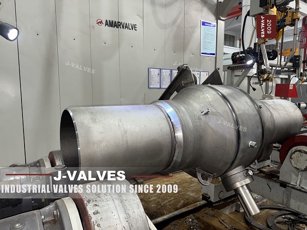
A welded body is bought for one reason: nobody wants to open it. Two girth welds instead of a body flange and a set of studs remove the joint that would otherwise be the first place a buried or a remote valve leaks, and the page states the consequence in a single line, a maintenance free life of more than fifty years. That claim is about the shell, and on the shell it holds.
The same page then fits an electric actuator to the top of that shell. The actuator has a motor, a gear train, limit switches, a torque switch, a heater and, on the intelligent version, a processor and a battery. Every one of those has a life measured in years or in operations, and none of them is welded. So the assembly has two service lives, and the one that governs the maintenance plan is the shorter one.
This page reads the valve from the top down. It is a twelve inch Class 300 valve, written as PN 50, with butt weld ends to ASME B16.25, a forged A105 shell and a trunnion mounted ball. The body is settled at this size. What is not settled is what the actuator has to be, how its protection is written, and what the operator should expect to replace first.
Design and Construction
The shell is built from a forged pipe section and two forged ends, welded around the circumference. There is no body flange and no bolted cover, so the only openings into the pressure boundary are the stem, the drain and the seat injection ports. The ball is carried on an upper and a lower trunnion, and at twelve inch those trunnions run in bearing blocks that are separate from the body rather than bores cut in the shell.
The stem passes through the top of the shell, and that penetration is the one place on a welded body where something moves. It is sealed by packing, held by a gland, and the shoulder that keeps the stem in place if the gland is removed is the anti blow out feature called for by API 6D. The packing can be renewed with the line live, which is the only maintenance operation this valve allows without cutting it out.
The ends are butt weld, machined to the ASME B16.25 profile and matched to the pipe specification. That detail is worth more attention than it usually gets, because the field weld is made between two documents: the valve end is cut to B16.25 and the pipe end is cut to whatever the pipeline specification says. Where those two do not agree, the fit up is ground to suit on site, and the root pass is where the disagreement ends up.

Actuator and Service Life
An electric quarter turn actuator is a small gearbox with a motor on one end and a handwheel on the other. The motor turns a worm or a planetary train, the train turns the stem through a quarter, two limit switches stop the travel at each end, a torque switch stops it earlier if something jams, and a heater keeps the inside of the enclosure above dew point. Every part in that list has an expected life, and only the mounting pad is welded.
| Part | What It Does | What Ends Its Life |
|---|---|---|
| Motor | Turns the gear train for the stroke | Brushes on a DC unit, winding insulation at temperature |
| Gear train | Multiplies torque down to the stem | Grease life, tooth wear at the torque switch setting |
| Limit switches | Define open and closed | Contact wear, and drift if the cam is not locked |
| Torque switch | Protects the valve from an obstruction | Setting drift after a seat is replaced |
| Heater and thermostat | Keeps the enclosure dry | Element failure, which shows as condensation first |
| Enclosure seals | Keep water and gas out | Age, and every time the cover is opened |
| Battery, intelligent type | Keeps the position record alive | Shelf life, not operating life |
| Mounting pad and bolts | Hold the actuator to the valve | Nothing, provided the pad was machined square |
The page offers protection as IP67 or IP68, and those two are not two grades of the same statement. IP67 is a defined test: immersion at one metre for thirty minutes. IP68 has no fixed number at all, because the standard requires the manufacturer to state the depth and the duration with the rating. A specification that reads IP68 without a suffix has not said anything that can be checked, and on a valve installed in a pit or a flooded chamber the difference between one metre for half an hour and continuous immersion is the whole question.
The explosion protection tells a similar story. This actuator is offered as Ex d IIB T4, which is gas group IIB and a surface temperature limit of 135 Celsius. The gas hydraulic version of the same valve is quoted as Ex d IIC T6. IIB excludes hydrogen and acetylene from the group, so an area classified as IIC cannot use this actuator at all, and a T4 limit is fifty degrees looser than a T6 limit. The two ratings belong to two different products and should never be carried across from one page to the other.
The duty class is the part that is most often left off an order. A motor driving a twelve inch valve for two minutes is running short time, and the standard duty designation for that is a short time rating with a stated period. An actuator built for on off service and then used for modulating control with a four to twenty milliamp signal will be asked to start far more often than its duty allows, and the first symptom is a thermal trip that looks like a torque problem.
Technical Specifications
The table is the build as the page states it. The class is written both ways on the page, Class 300 and PN 50, and those two are the same row of the class table in API 6D, so there is nothing to convert and nothing to correct.
| Item | Value |
|---|---|
| Size | 12 inch, DN 300 |
| Class | Class 300, PN 50 |
| Temperature | Minus 29 to plus 425 Celsius |
| Body | ASTM A105 forged carbon steel, welded shell |
| Body Options | A350 LF2 for minus 46, or A182 F316 |
| Ball | A105 with ENP or carbide coating, or solid F316 |
| Trunnion | Surface hardened A105 or 17-4PH, in bearing blocks |
| Stem | 17-4PH or nickel alloy 718 |
| Seat | PTFE or RPTFE, PEEK, or metal with graphite |
| Ends | Butt weld to ASME B16.25, flanged transition on request |
| Actuation | Electric, quarter turn or multi turn |
| Power Supply | 380, 220 or 24 volt, AC or DC |
| Enclosure | IP67, or IP68 with a stated depth and duration |
| Hazardous Area | Ex d IIB T4 on this actuator |
| Stroke Time | 15 to 120 seconds, set by torque and motor |
| Design and Test | API 6D and ASME B16.34, tested to API 6D and API 598 |
Two rows in that table are written as alternatives and should not be read as ranges. The temperature depends on the seat that is fitted, so a PTFE seat stops well below 425 and a metal seat with graphite reaches it. And the stroke time depends on the motor and the gear ratio, which are chosen for a torque; a single actuator does not offer both fifteen seconds and a hundred and twenty.
Standards and Compliance
API 6D governs the valve, ASME B16.34 supplies the wall and the ratings behind the class, and ASME B16.25 fixes the weld end profile. The actuator brings its own documents, and they are separate: the enclosure rating comes from IEC 60529, the hazardous area certification from IEC 60079, and the duty rating from the motor standards the manufacturer works to. A valve certificate does not cover the actuator, and that is the gap that shows up at a site audit.
| Document | What It Fixes | What It Does Not Cover |
|---|---|---|
| API 6D | Classes, test, marking, fire test | The actuator |
| ASME B16.34 | Wall, material groups, ratings | The internals |
| ASME B16.25 | Weld end profile | The field welding procedure |
| API 598 | Shell and seat test | The drive train |
| IEC 60529 | The meaning of IP67 and of an IP68 suffix | Whether the installation needs IP68 |
| IEC 60079 | Ex d, gas group and temperature class | The process gas inside the valve |
| IEC 60034 | Motor duty and rating | The gearbox life |
The enclosure rating deserves one more sentence because it is where specifications usually stop paying attention. IP67 is a test that is passed once, on a sample, and the certificate says so. A gasket that is compressed and released every time the cover comes off will not stay at the same rating for twenty years, which is why the maintenance interval on an actuator is set partly by how often somebody opens it.
Manufacturing Process
The body is welded, radiographed and then machined. The weld is made with the ends aligned and square to one another, because a shell welded out of line cannot be straightened afterwards and the seat pockets will show the error as uneven loading. After the weld the bore, the seat pockets, the trunnion housings and the mounting pad are cut, and the pad is the one that decides the actuator.
The pad is machined square to the stem axis, drilled to the actuator's bolt pattern and, where the pattern allows, spigoted so the drive is centred on the stem rather than on the bolts. An actuator bolted to a pad that is out of square will bind before it reaches either end of the quarter, and the torque switch will trip on a valve that is mechanically free. That is a machining defect that looks like an actuator fault.
Assembly then fits the stem from the top, sets the packing compression, fits the ball and seats through the ends before the end pieces are welded on, and tests the valve with a drive on the pad. Setting the limit switches at the works rather than at site is what makes the first commissioning a check rather than a setup.

Quality Control and Testing
The shell test is applied to the welded body at the multiple of the class that API 6D names, and the girth welds are the parts under observation. Because there is no body joint, a weep during this test cannot be blamed on a gasket, and the radiographs taken after welding are the record that the shell was sound before the test rather than after it.
The seat test is run from each side, with the leakage collected and compared against the acceptance the order states. On a soft seated valve at this class the acceptance is normally tight, and the test is where the seat and the ball finish are proved together rather than separately. The ball is lapped and the seat is moulded, and only the pair has a leakage figure.
The actuator is then stroked against the valve, the positions are set on the mechanical stops, the limit switches are set to those stops, the torque switch is set above the running torque with margin, and the heater is proved by measurement rather than by the lamp. The stroke time is measured at the specified supply voltage, because a motor that takes fifteen seconds at nominal voltage takes considerably longer at the bottom of the permitted band.

Applications and Industry Service
Metering and regulating stations are the first use, where a twelve inch Class 300 valve isolates a run that has to be opened for proving. The electric drive is chosen there because the station has power and because the valve has to be operable from a control room, and the welded body is chosen because the valve is often in a pit with groundwater in it.
The second use is any remote isolation point where power is available but attendance is not. A valve that is opened twice a year by a crew costs more in travel than in maintenance, and an electric actuator with a remote signal removes the journey. That is also the case where the actuator's protection and its heater matter most, because the enclosure is closed for years at a time.
The valve is the wrong choice where the area is classified for gas group IIC, because this actuator is IIB, and where the service needs modulating control at a rate the duty class does not allow. It is also the wrong choice where nobody will ever check the heater, because a failed heater in a damp pit is the most common way an electric actuator fails without moving.

Installation, Operation and Maintenance
The valve is welded into the line, so the installation is a fit up, a welding procedure and a radiograph of the field joints. After the weld cools, the body is checked for distortion at the flange faces of the mounting pad, and the actuator is fitted last so that the pad can be inspected without it in the way. The cable gland is the detail that decides whether the IP rating survives: an entry made from below with a proper gland and a loop of cable will stay dry, and one made from above without a loop will fill with water.
Operation is a quarter turn, and the two things worth recording are the stroke time and the running current. A stroke time that lengthens and a current that rises together point to the valve; a current that rises with a constant stroke time points to the gear train or the packing. Neither reading means anything without the value recorded at commissioning, which is why the commissioning sheet is part of the valve record rather than part of the contractor's file.
Maintenance is planned around the actuator because the body asks for none. The packing is checked for weep, the injection ports are proved, and the enclosure is opened as seldom as possible. Grease, seals, the heater and, on the intelligent version, the battery are the items with a schedule, and each of them is available above ground without disturbing the pressure boundary.
How to Specify and Order
The order lines below are the ones the page leaves open, and the first two decide whether the assembly can be maintained at all.
| Line on the Order | What to Write | Why It Matters |
|---|---|---|
| Enclosure rating | IP67, or IP68 with the depth and the duration stated | IP68 without a suffix cannot be checked |
| Hazardous area | Gas group, temperature class and zone | This actuator is IIB T4, not IIC T6 |
| Duty | On off or modulating, with the starts per hour | The motor rating follows the duty, not the valve |
| Stroke time | The time required at the lowest supply voltage | Rated voltage time is the best case |
| Supply | Voltage, phase, and the permitted band | A motor at the bottom of the band is slower |
| Seat and temperature | Seat material and the temperature it allows | The body range is not the seat range |
| Ends | Weld end profile and the pipe grade it joins | The field weld is made to both |
| Heater and thermostat | Fitted, and how it is proved at commissioning | A dead heater is a silent failure |
Read as a whole, the page describes a valve that is meant to be forgotten and a drive that cannot be. The welded shell, the trunnion and the butt weld ends will outlast the pipeline they sit in if the medium is kind. The actuator is the part that will be replaced, and the only question worth settling at the order stage is whether it was specified for the place it is going, or for the page it was copied from.
FAQ
Q: Why is the body life quoted in decades and the actuator in years?
A: Because the body has no wear part. A welded shell has two girth welds, a machined bore and a stem penetration, and none of those consumes itself while the valve sits still. The actuator has a motor, a gear train, switches, seals and a heater, and each of them has a finite life whether the valve moves or not.
Q: What does IP68 actually mean on an actuator?
A: Nothing on its own. The standard requires the manufacturer to state the depth and the duration with the rating, so a valid marking reads IP68 followed by two numbers. IP67, by contrast, is fixed: one metre for thirty minutes. A specification that says IP68 without a suffix cannot be checked at the works or at site.
Q: This valve is offered as Ex d IIB T4. Can it go where IIC is required?
A: No. IIB excludes hydrogen and acetylene from the gas group, and the temperature class T4 allows a hotter surface than T6. An area classified IIC needs an actuator certified for IIC, and the gas hydraulic version of this same valve is offered as IIC T6, which is a different product on the same pad.
Q: Can the same electric actuator be used for on off and for modulating duty?
A: Not usually. On off service starts the motor a few times a shift; modulating service starts it continuously, and the motor rating that suits one does not suit the other. An on off unit put on a control loop trips on its thermal protection, and the trip is often misread as a torque problem.
Q: How long should the stroke take on a twelve inch valve?
A: Long enough that the motor is not asked for more torque than it has. Fifteen seconds and a hundred and twenty seconds are not two settings of one unit; they are two different gear ratios and motors. The figure that belongs on the order is the time required at the lowest supply voltage, not at nominal.


Hot Products


News
Urea Plant Ball Valves: The Wetted Path Survives Only While Oxygen Is Being Fed To It
Carbamate at 150 bar and 185 C eats stainless 50 times faster once the passive film starves. The valve cavity is where the oxygen runs out first.
Read More
Stiction: What A Ball Valve Becomes When Nobody Turns It
A valve that stood closed for years has not worn out. The seat has bonded to the ball, and the first stroke is a step, not a ramp. What the trace shows.
Read More
Molten Salt Ball Valves: The Valve Works at 565 C And Dies at 219 C
Salt freezes at 220 C and decomposes at 565 C. Everything a molten salt ball valve does happens in that 345 kelvin gap, and the gap is not generous.
Read More
Direct Air Capture Ball Valves The Vacuum Side Runs The Seal Backwards, And Three Hundred Thousand Strokes Decide The Design
A solid sorbent DAC plant moves 1.3 million cubic metres of air per tonne of CO2, then asks a DN50 ball valve to hold 0.9 bar from the wrong side.
Read More