


CHINA J-VALVES Offers Various High-quality I ndustrial Ball Valves
J-VALVES, a distinguished professional ball valve manufacturer rooted in China, takes pride in its extensive product portfolio. Our offerings span a wide range, including trunnion-mounted ball valves, floating ball valves, high-temperature ball valves, high-pressure ball valves, metal-sealed ball valves, ultra-low temperature ball valves, DBB ball valves, Three-way And Four-way Ball Valve, and fully welded ball valves. Each product is a testament to our commitment to precision engineering and reliable performance. Meticulously crafted, they are designed to not only meet but exceed the most stringent industrial demands, ensuring stable operation even under extreme conditions. This enables us to provide our clients with high-value services and makes our valves widely sought-after in industries.
Product Category
Contact Us

-
J-VALVES-Q367F
-
J-VALVES
Overview of the J-VALVES forged steel fully welded trunnion ball valve with sleeves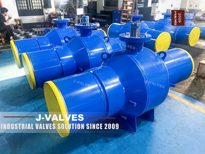
The product name on this page ends with the words Wish Sleeves. It is written that way eleven times: in the heading, in the browser title, in every image caption and in the address of the page itself. The photograph at the top of the page is saved under a different name, and that name says with sleeves. One letter apart, and that letter decides whether a buyer looking for a welded valve with transition pieces ever arrives here.
The valve behind the name is real, and the sleeve is a real part. It is a short length of forged pipe welded to each end of the body, made either in the steel of the body or in the steel of the line it will join. Its job is to move a weld. On a line of X70 or X80 pipe, a valve in A105 has to be joined by a weld between two different steels, and that weld needs its own procedure, its own preheat, a matching consumable and a hardness check. Put a transition piece on the valve in the shop and the field weld becomes X70 to X70.
This page is about that piece. It is a six to fifty six inch welded trunnion valve with a forged transition at each end, and the rest of the construction is the one this family uses everywhere. What is not settled is what the sleeve carries, what it cannot carry, and what has to be on the drawing before the body is welded.
Design and Construction
The body is a welded shell. A forged pipe section in the middle, a forged end at each side, joined by circumferential welds, with no body flange and no bolted cover. The ball runs on an upper and a lower trunnion, so the pressure load goes into the bearings and the seats only have to seal. The stem leaves the body through graphite packing held by a shoulder, and each seat can be reached through an injection port at the body.
The sleeves are welded on after the body is complete. That makes them the last two girth welds on the assembly, and it makes them part of the pressure boundary. The steel between the body and the field weld sits at line pressure, so its wall thickness, its corrosion allowance and its design pressure belong to the pipe specification rather than to the valve class.
The photograph shows the arrangement without needing the drawing. Two long cylinders, each ending in a bare ring, and a circumferential seam on each side where the cylinder meets the body. A gearbox with a handwheel sits on the top flange, the injection lines are brought out to a small manifold at the front, and two feet are welded under the shell to carry the weight on a foundation.
That is the whole external description, and it is worth counting what it contains: two sleeve welds, one top flange, one drain, two injection points and two feet. Every one of them crosses or touches the pressure boundary, and the claim that a welded body has no external leakage path has to be read against that list rather than against the absence of a body joint.
The seams are the reason the count matters. A body welded from a pipe section and two ends has at least two circumferential joints, and a body with sleeves has two more. None of them is a flange and none of them can be opened, so the only way to know a shell is sound is to have radiographed each one before the coating went on.

The Sleeve Is a Weld, Not a Liner
The word sleeve invites the wrong reading. A sleeve in a pipeline is often a liner, a piece pushed inside a pipe to bridge a defect, and a liner carries nothing. This sleeve is outside the pipe, it is butt welded at both ends, and it is at full line pressure. It is a pup piece with a transition built into it, and the difference matters because a liner can be specified by length while a pup piece has to be specified by wall thickness, steel and weld procedure.
The reason to fit one is metallurgical. Welding A105 to X70 in the field means a dissimilar joint in a trench, with preheat that has to be held, a consumable chosen for both sides, and a hardness limit that has to be checked afterwards or not at all. Moving that joint into the shop means it can be radiographed, it can be stress relieved, and it can be proved before the coating goes on. What is left in the trench is a weld between two lengths of the same line pipe.
| What the Sleeve Does | What It Does Not Do | Who Owns It |
|---|---|---|
| Moves a dissimilar weld from the trench into the shop | It does not absorb ground movement | The valve maker, working to the pipeline specification |
| Puts the field weld in line pipe steel | It does not take up thermal expansion | The pipeline designer |
| Keeps the body heat affected zone away from the field weld | It does not align two pipes that are not parallel | The installer |
| Leaves room for coating cut back and a field joint | It does not replace a bend or an expansion loop | The coating contractor |
The page makes one claim about the sleeve that does not survive that table. It says the transition sleeves accommodate soil settlement and pipeline displacement. A forged pup piece welded at both ends is a rigid length of pipe. It transmits settlement rather than absorbing it, and the parts that absorb movement are a bend, an expansion joint or a flexible coupling, none of which is welded to the valve.
The length on the page runs from one hundred and fifty to five hundred millimetres, with longer pieces to the project drawing. The number has three drivers, and only one of them is the weld. It has to keep the field weld far enough from the body that the heat of it does not reach the body seam. It has to leave room for the coating cut back and for the sleeve that will be shrunk over the joint. And it has to be long enough that the field crew can get a clamp and a torch onto it without dismantling anything.
There is a fourth consequence that is easy to miss. The sleeve is where the coating stops, and the cut back is bare steel by definition. On a buried line that bare ring is the place corrosion starts, which is why the field joint and its test matter as much as the sleeve itself. The sleeve does not solve the coating problem; it creates a defined place for the problem to be solved.
Technical Specifications
The table below is the build as the page states it, with two corrections. The page offers PTFE and RPTFE down to minus forty six, which is a seat temperature and not a body temperature: the A105 shell on this valve stops at minus twenty nine, and the lower figure only holds if the body is ordered in A350 LF2. The class range is written as PN 20 to PN 420, which is the correct set of designations for Class 150 to Class 2500.
| Item | Value |
|---|---|
| Size range | 6 inch to 56 inch, DN 150 to DN 1400 |
| Pressure class | Class 150 to Class 2500, PN 20 to PN 420 |
| Temperature | Minus 29 to plus 425 Celsius, carbon steel body |
| Body | ASTM A105 forged carbon steel, welded shell |
| Body options | A350 LF2 to minus 46, A694 F52 or F65, A182 F316 or F316L |
| Sleeves | Forged, body steel or line pipe steel such as API 5L X70 and X80 |
| Sleeve wall | To ASME B31.3 or B31.8, with the corrosion allowance of the line |
| Sleeve length | 150 to 500 mm standard, longer to the project drawing |
| Ball | A105 with ENP, hard chrome or tungsten carbide, or solid F316 |
| Trunnion | Surface hardened A105 or 17-4PH |
| Seat | PTFE or RPTFE to 180 Celsius, PEEK to 260, metal with graphite to 425 |
| Seat design | Single piston effect standard, double piston on request |
| Stem | 17-4PH or nickel alloy 718 |
| Packing | Graphite, wire reinforced |
| Ends | Butt weld to ASME B16.25, with the sleeve as the transition |
| Coating | Three layer polyethylene or fusion bonded epoxy, cut back at both ends |
| Design | API 6D and ASME B16.34 |
| Test | API 6D and API 598 |
Two rows carry the argument. The sleeve wall row does not name a valve standard, because the sleeve is pipe and is designed as pipe. And the ends row names the profile at the far end of the sleeve, not at the body, because that is the face the field crew will actually weld.
The page also says the seats tighten against the ball when cavity pressure rises, to prevent overpressure. That is the one place where the text contradicts the table above it. A double piston seat is pressed toward the ball by cavity pressure as well as by line pressure, so the cavity is the one volume that cannot relieve itself. The same page prints a seat table that says exactly this, with self relieving marked yes for single piston and no for double. Where the text and the table disagree on this valve, the table is right.
Standards and Compliance
API 6D governs the valve, ASME B16.34 the wall and the ratings, and neither of them describes a transition piece. That is not a gap in the standards; it is a boundary. The sleeve belongs to the pipeline, and its wall is calculated as pipe under B31.3 or B31.8, with the design factor, the corrosion allowance and the temperature derating of the line it will serve.
| Document | What It Fixes | What It Leaves Open |
|---|---|---|
| API 6D | Valve classes, test, marking, cavity relief | The sleeve, which is not a valve part |
| ASME B16.34 | Wall and ratings of the valve body | The pipe wall of the sleeve |
| ASME B31.3 and B31.8 | The sleeve designed as pipe | The weld between sleeve and body |
| ASME B16.25 | The weld end profile | The line pipe end it will meet |
| API 5L | The line pipe steel the sleeve may match | The joint between two different steels |
| ASME IX and API 1104 | The procedure and its qualification | Whether the joint is made in a shop or a trench |
| NACE MR0175 | Material limits for sour service | The hardness at the transition, which is measured |
The consequence for an order is that two standards have to be named on one drawing. The valve is bought to API 6D. The sleeve is bought to the pipeline specification. If only the first is written down, the sleeve will be made in body steel at body wall, and the field weld will be a dissimilar joint after all, which defeats the purpose of paying for the sleeve.
Sour service adds a third line. NACE MR0175 limits hardness in the weld and the heat affected zone, and the transition is the place where two steels with different hardenability meet. A procedure qualified on the body steel alone does not qualify the joint, and the hardness check has to be taken on the transition rather than on the pipe.
Manufacturing Process
The body starts as a forged pipe section and two forged ends. The ends are machined with the weld preparation before welding, the joints are aligned and tacked, and the circumferential seams are made by gas metal arc or submerged arc welding under a qualified procedure. After welding the shell is radiographed, stress relieved where the wall requires it, and machined for the ball, the seats, the stem bore and the ports.
The sleeves are welded on at the end of that sequence, not the beginning. Doing it the other way round would mean machining a body with two long pipes hanging off it, and would put the sleeve welds through the heat treatment of the body. Welding them last also means the sleeve seams can be radiographed on their own, with the body already proved.
The weld preparation at the far end is the part that most often arrives wrong. The page specifies ASME B16.25, and the pipe on site may be cut to the same standard or to a contractor's profile. The two are not the same shape, and a preparation that does not match the pipe means a root gap that cannot be closed or a land that has to be ground out in the trench.
Coating comes last, and it comes with a decision. The sleeve is coated with the body, then cut back at each end to bare steel for a length agreed with the field joint. That cut back is not a defect and it is not an economy; it is the working space for the weld, and its length is set by the welding process and by the sleeve that will cover the joint.

Quality Control and Testing
Every girth weld on the shell and on the sleeves is radiographed, which is what the page means by full radiographic testing. The shell and seat tests follow to API 6D and API 598, and they are done before the coating, because a leak found after coating is a leak found after the cut back has been made and the surface prepared.
The test that belongs to the sleeve specifically is the procedure qualification. A welded joint between A105 and X70 is proved by a procedure test that includes a tensile, a bend and a hardness survey across the joint, and the hardness is read in the weld and in both heat affected zones. That record is what a pipeline inspector will ask for, and it is not the same document as the valve test report.
The sleeve itself is checked for wall thickness at four points, for length against the drawing, and for roundness at the far end, because a sleeve that is oval cannot be aligned to a round pipe without a clamp that distorts it. The coating on the sleeve is holiday tested along with the body, and the cut back is measured rather than estimated.

Applications and Industry Service
Transmission lines are the first use, and the reason is the steel. A line built in X70 or X80 will have valves in A105 because that is what valve bodies are forged in, and every one of those valves is a dissimilar joint unless something is done about it. A sleeve is the cheapest thing that can be done about it, and it is done once, in a shop, under cover.
The second use is a station or a tie-in where the pipe and the valve come from different specifications. The sleeve lets the valve be bought to one standard and the transition be designed to another, and it puts the interface at a place where a weld can be inspected rather than at a place where it can only be covered up.
The valve is the wrong choice where the ground is expected to move. A rigid sleeve does not absorb settlement, and a line that crosses a settling area needs a bend or an expansion element at the valve rather than a longer transition piece. It is also the wrong choice where the field crew cannot radiograph, because the joint at the far end of the sleeve is still a weld and still needs proving.

Installation, Operation and Maintenance
Installation starts at the cut back. The sleeve is left bare for an agreed length, the pipe is cut to match, and the two are aligned so that the bore is continuous and the root gap is even. The weld is made to the pipeline procedure, which for a line pipe sleeve is the same procedure the rest of the line uses, and that is the point of the part.
After welding, the joint is coated and the coating is tested. A holiday test on the field joint is not optional on a buried line, because the joint is the one place where the factory coating was deliberately removed, and a pinhole there is a pinhole at the most exposed point of the assembly.
Operation and maintenance are unchanged by the sleeve. The valve is operated from the top, the seats are injected at the body ports, and the cavity is drained at the drain. What the sleeve changes is access: on a buried valve the ports are below ground, and the sleeves are what the excavation exposes first, which is one more reason their length and their coating matter.
How to Specify and Order
The lines below are the ones the page leaves open, and the first two decide whether the sleeve does its job or merely adds two welds.
| Line on the Order | What to Write | Why It Matters |
|---|---|---|
| Sleeve steel | Body steel or the line pipe steel, named | The field weld follows from this line |
| Sleeve wall and standard | B31.3 or B31.8, with the corrosion allowance | The sleeve is pressure boundary |
| Sleeve length | The length and the cut back, both | Coating and clearance follow from them |
| End preparation | B16.25 or the pipe profile, not both at random | The two shapes do not match |
| Weld procedure | The shop procedure and its qualification | It is the reason the sleeve exists |
| Radiography | The extent on the sleeve welds | They are the last welds on the body |
| Coating at the sleeve | The system and the field joint standard | The cut back is where corrosion starts |
| Product name | With, not Wish | A search for the part should find the part |
Read as a whole, the page describes a valve whose hardest weld has been moved indoors. The body is settled, the trunnion is settled, the seats are a choice. What decides whether the assembly works is whether the sleeve was specified as a piece of pipe with a steel, a wall and a procedure, or as a length of pipe with a nice name attached to it.
FAQ
Q: What is a transition sleeve on a fully welded valve?
A: A short length of forged pipe welded to the end of the body, made either in the body steel or in the steel of the line it will join. Its purpose is to move the joint between two different steels out of the trench and into the shop, so that the weld made on site is line pipe to line pipe and can use the same procedure as the rest of the line.
Q: Can the sleeve absorb ground settlement, as the page says?
A: No. A forged pup piece welded at both ends is a rigid length of pipe; it transmits settlement rather than absorbing it. Movement is absorbed by a bend, an expansion joint or a flexible coupling, and none of those is welded to the valve. A line across settling ground needs one of those at the valve, not a longer sleeve.
Q: Why does the page call it Wish Sleeves?
A: It is a misspelling of with, and it appears eleven times, including the page address. The photograph on the same page is saved as forged-steel-fully-welded-ball-valve-with-sleeves, which is the correct name. The spelling is corrected throughout this page; the address needs a redirect once the name is fixed.
Q: Is the sleeve part of the pressure boundary?
A: Yes. It sits between the body and the field weld with line pressure inside it, so its wall, its corrosion allowance and its design pressure belong to the pipeline specification rather than to the valve class. That is why the sleeve is designed as pipe to ASME B31.3 or B31.8 and not as a valve part.
Q: Does a sleeve change the valve class or the face to face length?
A: Neither. The class comes from the body and the seats, and the face to face dimension is measured over the body, not over the sleeves. What the sleeve does change is the overall length of the assembly and the position of the field weld, both of which have to be shown on the drawing.


Hot Products


News
Urea Plant Ball Valves: The Wetted Path Survives Only While Oxygen Is Being Fed To It
Carbamate at 150 bar and 185 C eats stainless 50 times faster once the passive film starves. The valve cavity is where the oxygen runs out first.
Read More
Stiction: What A Ball Valve Becomes When Nobody Turns It
A valve that stood closed for years has not worn out. The seat has bonded to the ball, and the first stroke is a step, not a ramp. What the trace shows.
Read More
Molten Salt Ball Valves: The Valve Works at 565 C And Dies at 219 C
Salt freezes at 220 C and decomposes at 565 C. Everything a molten salt ball valve does happens in that 345 kelvin gap, and the gap is not generous.
Read More
Direct Air Capture Ball Valves The Vacuum Side Runs The Seal Backwards, And Three Hundred Thousand Strokes Decide The Design
A solid sorbent DAC plant moves 1.3 million cubic metres of air per tonne of CO2, then asks a DN50 ball valve to hold 0.9 bar from the wrong side.
Read More