


CHINA J-VALVES Offers Various High-quality I ndustrial Ball Valves
J-VALVES, a distinguished professional ball valve manufacturer rooted in China, takes pride in its extensive product portfolio. Our offerings span a wide range, including trunnion-mounted ball valves, floating ball valves, high-temperature ball valves, high-pressure ball valves, metal-sealed ball valves, ultra-low temperature ball valves, DBB ball valves, Three-way And Four-way Ball Valve, and fully welded ball valves. Each product is a testament to our commitment to precision engineering and reliable performance. Meticulously crafted, they are designed to not only meet but exceed the most stringent industrial demands, ensuring stable operation even under extreme conditions. This enables us to provide our clients with high-value services and makes our valves widely sought-after in industries.
Product Category
Contact Us


-
J-VALVES-Q41F
-
J-VALVES
Overview of the J-VALVES three inch Class 150 CF8M two piece floating ball valve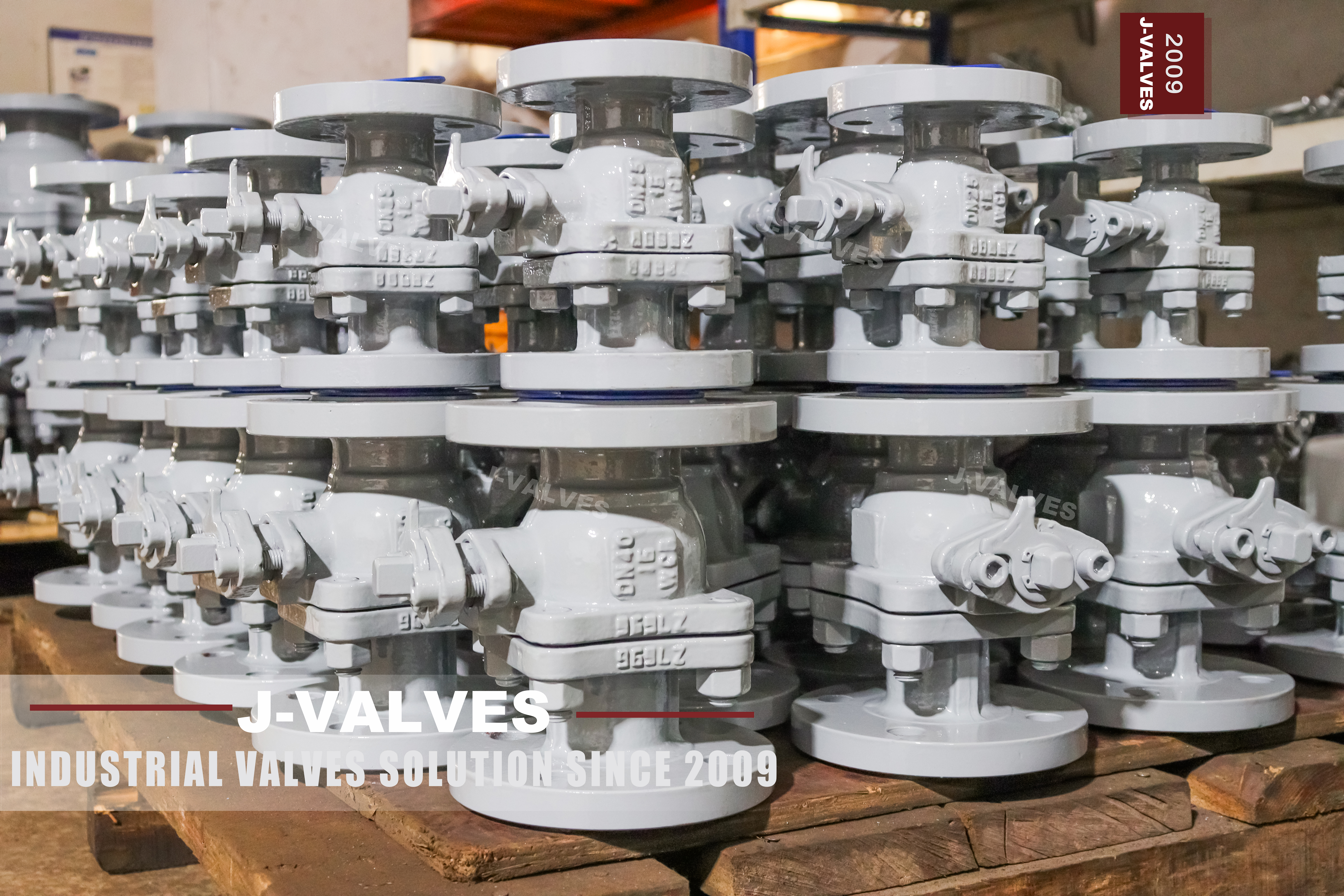
The photograph on this page shows a valve with a bare square stem, a gland plate with four studs, and a stop plate under it. There is no lever. The specification block beside the photograph lists the operation as manual, lever or worm gear, and the valve in the picture is neither of those: it is a valve waiting for a drive, shipped in the state that lets the buyer fit whatever drive the line needs.
That is not a small difference and it is not a packaging detail. A valve that arrives with a lever is a manual valve. A valve that arrives with a bare stem is an actuator-ready body, and the responsibilities that normally sit with the valve maker, such as setting the stops and proving the travel, move to whoever fits the drive.
The valve itself is a three inch Class 150 two piece floating ball valve cast in CF8M, with raised face flanges and a bolted body joint. This page is about the part of it that is decided after the valve is built: what is in the crate, what the pad has to match, and how a valve with no handle is tested and set.
Design and Construction
The body is cast in two pieces. One half carries the ball and the seats, the other closes over them, and the two are joined at a flange with four studs and nuts. Cast into the body are the grade CF8M and the figures 3-150, and a short code is cast on each of the joint lugs, which is how a foundry ties a body back to its pattern and its heat.
The ball floats. It is not carried on trunnions; it is located by the two seats and pushed downstream by the pressure, which is what makes the downstream seat the sealing element and the body joint the part that carries the thrust. At three inch and Class 150 the thrust is modest, which is why a floating design is the normal choice at this size and a trunnion is not.
The joint is worth counting because it is the whole structural difference between this valve and a welded one. Four studs, two gasket faces and one gasket sit between the ball and the pipe, and every one of them is a pressure boundary that can be opened with a wrench. That is the trade: access to the seats in exchange for a joint that has to be made correctly every time it is remade.
The flanges are raised face to ASME B16.5 and the face to face dimension follows B16.10 for a flanged valve. Those two tables fix everything a buyer can measure from outside, and nothing inside: the bore, the seat width and the cavity volume are not in either standard and are not on the page.

What Arrives in the Crate
There are four states a ball valve can be shipped in, and the page names two of them. A bare stem is the first: the valve is complete except for the drive, the stem is a square or a keyed shaft, and the pad above the gland is machined to take a mounting bracket. A lever is the second, and it is simply a handle clamped to that same stem. A gearbox is the third, bolted to the same pad. An actuator is the fourth, and it brings its own bracket and coupling.
| Delivery State | What It Needs to Be Complete | Who Sets the Stops |
|---|---|---|
| Bare stem | A drive, a bracket and a coupling | Whoever fits the drive |
| Lever | Nothing; the lever is clamped on | The maker, at assembly |
| Gearbox | A bracket matched to the pad | The maker or the gearbox supplier |
| Actuator | Air, power or hydraulic supply, and wiring | The actuator supplier, on site |
The stop plate is the part that makes the difference practical. A quarter turn valve has two hard stops, and they have to be set so that the ball lands on the seat without being driven into it. On a lever valve the stops are in the lever quadrant and are set at the factory. On a bare stem valve the stops are in the plate under the gland, and they are set to the ball before the valve leaves, which is why the plate is bolted rather than cast in one piece with the body.
Testing a valve with no handle is done on the square. The stem is turned with a wrench or a socket, the ball is brought to each seat, and the seat test is run in the direction that seat is loaded. This is the same test a lever valve gets; what changes is that the torque comes from a tool rather than from a hand, and the tool leaves no mark on a properly protected square.
The consequence for a buyer is a question worth asking before the order rather than after. If the valve is going onto a skid that already has an actuator, a bare stem is the cheaper and the more honest purchase, because a lever that will be thrown away is a lever that was paid for. If the valve is going into a line and nobody knows yet how it will be operated, a lever is the safer purchase, because a bare stem valve in service with no drive is a valve nobody can close.
Technical Specifications
The table is the build the page describes, with the range narrowed to the size on the nameplate. The page prints one quarter inch to twelve inch and Class 150 to 2500 as the family range, which is true of the family and not true of this valve: the unit in the photograph is three inch and Class 150, and the figures 3-150 are cast into it.
| Item | Value |
|---|---|
| Nominal size | 3 inch, DN 80 |
| Pressure class | Class 150, PN 20 |
| Temperature | Minus 20 to plus 180 Celsius, per the seat fitted |
| Body | ASTM A351 CF8M cast stainless steel, two pieces |
| Body joint | One gasketed joint, four studs |
| Ball | CF8M, mirror polished |
| Ball support | Floating, located by the seats |
| Stem | 316 stainless, blowout proof shoulder |
| Stem drive | Bare square, lever, gearbox or actuator |
| Stem seal | PTFE or flexible graphite packing, adjustable gland |
| Seat | PTFE or RPTFE |
| Stop | Bolted stop plate, set to the ball before dispatch |
| Ends | Raised face flange to ASME B16.5, Class 150 |
| Face to face | ASME B16.10, flanged valve table |
| Bore | Full bore at this size |
| Design | ASME B16.34 and API 608 |
| Test | API 598, seat tested from the loaded side |
| Marking | Grade and size cast into the body |
Three rows carry the argument. The stem drive row is a list because the valve is sold in four states, and the row above it is the reason the list exists. The stop row is the one that is almost never written on a data sheet and is the one that decides whether the ball seats or is overdriven. And the marking row says cast rather than stamped, which is why the grade survives on this valve where a plate would not.
The temperature line is where these pages usually drift. The seat in this valve is PTFE or RPTFE, and neither is a high temperature seat; the family range on the page reaches four hundred and twenty five Celsius with a metal seat, which is a different valve with a different body and a different price. On this build the seat sets the limit.
Standards and Compliance
API 608 applies here without argument, which is worth saying because it does not apply to most of the valves on this site. The standard covers steel ball valves up to DN 600 and Class 600, and a three inch Class 150 valve sits comfortably inside both limits. Above those limits the governing standard is API 6D, and pages that quote 608 for a 1500 or 2500 class valve are quoting a document that does not reach them.
| Document | What It Fixes | What It Leaves Open |
|---|---|---|
| API 608 | Design, test and marking for this size and class | The pad pattern above the stem |
| ASME B16.34 | Wall and pressure ratings | The seat material and its limit |
| ASME B16.5 | Flange dimensions and drilling | The gasket that goes between them |
| ASME B16.10 | Face to face for a flanged valve | The bore, which is not in the table |
| API 598 | Shell and seat test | The torque needed to seat the ball |
| ISO 5211 | The mounting pad and the coupling | Whether a drive is fitted at all |
| ISO 5208 | Leakage rate classes | Which rate was ordered |
The pad standard is the one that matters for a bare stem valve, and it is the one the page never mentions. ISO 5211 fixes the pad size, the bolt circle, the number of holes and the shape of the drive, so that a valve bought bare can take a drive bought elsewhere. Without that line on the drawing, the drive arrives with a bracket that does not fit and a coupling that does not engage.
Manufacturing Process
The body halves are cast in CF8M, cleaned, and machined on the joint faces first, because everything else is referenced to them. The bore and the seat pockets are cut from the joint face inward, the flange faces are machined square to the bore, and the stem bore is cut last, square to the seat pockets so that the ball sits true between the two seats.
Assembly is a sequence of fits. The ball is polished and checked for roundness, the seats are fitted dry, the stem is inserted from inside with its shoulder against the body, and the two halves are brought together with a new gasket and four studs. The gland is then packed and adjusted, and the stop plate is set so that the ball travels a quarter turn between two hard stops.
The setting of the stops is the step that a bare stem valve cannot skip, because there is no lever to correct afterwards. The ball is brought to the closed position, the stop is set against it, and the same is done at the open end. A valve that stops a few degrees short of the seat will pass a seat test cold and weep when the line is hot, because the seat has not been loaded.
Marking and packing come last. The grade and the size are already in the casting; the heat code on the lugs is checked against the certificate; and the flange faces and the bore are protected before the valve goes into its crate.

Quality Control and Testing
The shell test and the seat test are to API 598, with the shell test proving the body and the joint and the seat test proving each seat in the direction it is loaded. On a floating valve the upstream seat is not a barrier, so a test that pressurises both sides and expects both seats to hold is testing a different design.
The check that belongs to this valve is the stop setting. With the valve on the bench, the stem is turned against each stop and the ball position is read through the bore. The angle between the two stops is a quarter turn, and the ball has to be on its seat at each end of it, not near it.
The pad is checked for flatness and for pattern, because a bare stem valve is bought for a drive that has not arrived yet. The square or keyed drive is measured, the bolt circle is checked against the pad standard, and the stem height above the pad is recorded, since a coupling that is too shallow will bottom on the stem and load it in tension.

Applications and Industry Service
The first use is a skid or a package where the actuator is chosen by the package builder rather than by the valve buyer. In that case a bare stem is the correct purchase: the valve is a body with a proven seat, and the drive and its controls are one system bought from one supplier.
The second use is chemical and water service at moderate temperature, which is what CF8M and a PTFE seat are for. Three inch Class 150 with raised face flanges is the common size for a branch isolation on a stainless line, and the floating design is adequate at that combination of size and pressure.
The valve is the wrong choice above its pressure class, where a floating ball at that bore starts to need torque a lever cannot deliver; and it is the wrong choice where the line will be hot enough to take the seat past its limit. It is also the wrong choice where nobody will fit the drive, because a bare stem valve left bare is a valve that cannot be operated.

Installation, Operation and Maintenance
Installation of the body is two flange joints, with new gaskets, the studs lubricated, and the bolts tightened in a cross pattern to the torque the gasket requires. The valve goes in with the ball open, so that the seats are not loaded by the flange bolts pulling the body faces together.
Fitting the drive is the step that decides whether the valve works. The bracket is bolted to the pad, the coupling is engaged on the stem square, and the actuator is stroked to each end before the coupling is finally tightened. If the actuator is set first and the valve second, the stops will fight each other and the ball will be driven past its seat.
Operation is a quarter turn, and the two things worth recording are the torque at breakaway and the position of the indicator at each stop. Maintenance is the gland, which is adjustable and can be tightened without removing anything, and the seats, which need the body joint opened and the line isolated.
How to Specify and Order
The lines below are the ones the page leaves open, and the first two are the ones that turn a body into a working valve.
| Line on the Order | What to Write | Why It Matters |
|---|---|---|
| Delivery state | Bare stem, lever, gearbox or actuator | It decides what has to be added later |
| Pad pattern | ISO 5211 size, with the drive type | A drive bought elsewhere has to fit |
| Stem drive | Square size or keyed shaft, and its height | The coupling depends on both |
| Stop setting | Set to the ball, and how it is proved | A bare stem has no lever to correct it |
| Size and class | 3 inch Class 150, per the casting | The family range is not this valve |
| Seat | PTFE or RPTFE, and the temperature | The seat sets the limit, not the body |
| Flange facing | Raised face to B16.5, and the gasket | The joint is the pressure boundary |
| Test | API 598, with the rate stated | A rate is an acceptance criterion |
Read as a whole, the page describes a valve that is finished except for the part that operates it. The casting, the joint, the seats and the stops are all settled before dispatch. What is not settled is who fits the drive, and that question is answered by the delivery state line on the order rather than by anything in the specification block.
FAQ
Q: Is a valve with no lever a defective valve?
A: No. A bare square stem is a delivery state, not a missing part. The valve is complete as a pressure boundary and as a seat, and the drive is deliberately left off so that the buyer can fit the actuator, gearbox or lever that suits the line. What it does mean is that the stops and the travel have to be set by whoever fits the drive.
Q: What has to match between the valve and the drive?
A: Three things: the pad pattern, the coupling and the stop setting. The pad pattern fixes the bolt circle and the pad size, the coupling has to engage the stem square at the right height, and the stops have to be set against the ball afterwards. A drive that fits the pad but bottoms on the stem will load the stem in tension.
Q: Does the family range on the page apply to this valve?
A: No. The page prints one quarter inch to twelve inch and Class 150 to 2500 as the range of the family, and the valve in the photograph is three inch Class 150, with both figures cast into the body. The range describes what the foundry can make; the casting describes what this valve is.
Q: Why is API 608 the right standard here?
A: Because this size and class sit inside its limits. API 608 covers steel ball valves up to DN 600 and Class 600, and a three inch Class 150 valve is well within both. Pages that cite the same standard for a 1500 or 2500 class valve are citing a document that stops well short of them.
Q: How is the seat tested on a valve with no handle?
A: On the square. The stem is turned with a socket or a wrench, the ball is brought against each seat in turn, and the seat test is run in the direction that seat is loaded. It is the same test a lever valve gets, with a tool providing the torque instead of a hand.



Hot Products


News
Urea Plant Ball Valves: The Wetted Path Survives Only While Oxygen Is Being Fed To It
Carbamate at 150 bar and 185 C eats stainless 50 times faster once the passive film starves. The valve cavity is where the oxygen runs out first.
Read More
Stiction: What A Ball Valve Becomes When Nobody Turns It
A valve that stood closed for years has not worn out. The seat has bonded to the ball, and the first stroke is a step, not a ramp. What the trace shows.
Read More
Molten Salt Ball Valves: The Valve Works at 565 C And Dies at 219 C
Salt freezes at 220 C and decomposes at 565 C. Everything a molten salt ball valve does happens in that 345 kelvin gap, and the gap is not generous.
Read More
Direct Air Capture Ball Valves The Vacuum Side Runs The Seal Backwards, And Three Hundred Thousand Strokes Decide The Design
A solid sorbent DAC plant moves 1.3 million cubic metres of air per tonne of CO2, then asks a DN50 ball valve to hold 0.9 bar from the wrong side.
Read More