


CHINA J-VALVES Offers Various High-quality I ndustrial Ball Valves
J-VALVES, a distinguished professional ball valve manufacturer rooted in China, takes pride in its extensive product portfolio. Our offerings span a wide range, including trunnion-mounted ball valves, floating ball valves, high-temperature ball valves, high-pressure ball valves, metal-sealed ball valves, ultra-low temperature ball valves, DBB ball valves, Three-way And Four-way Ball Valve, and fully welded ball valves. Each product is a testament to our commitment to precision engineering and reliable performance. Meticulously crafted, they are designed to not only meet but exceed the most stringent industrial demands, ensuring stable operation even under extreme conditions. This enables us to provide our clients with high-value services and makes our valves widely sought-after in industries.
Product Category
Contact Us


-
J-VALVES-Q41F
-
J-VALVES
Overview of the J-VALVES three inch 150LB CF3M two piece floating ball valve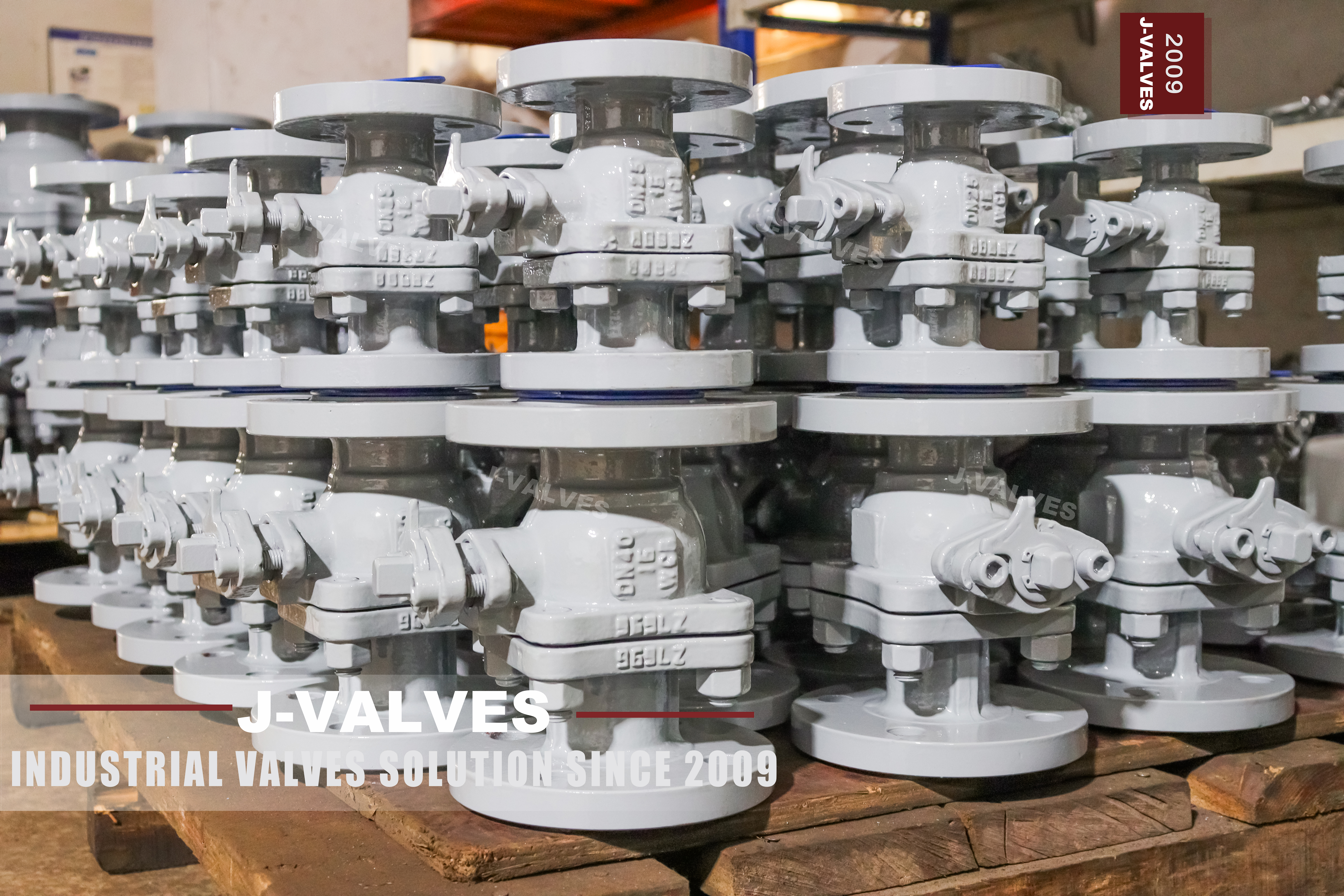
A two piece body is usually sold as a convenience: one joint instead of two, less to undo when the seats are replaced. That is true and it is the least interesting thing about it. The joint in a floating ball valve is not a lid over the works. It is a pressure retaining joint, and it carries the whole axial load that the medium puts on the closed ball.
The reason is the difference between floating and trunnion. On a trunnion valve the ball is held by two shafts and the seats only seal. On a floating valve the ball is free, the pressure pushes it downstream, the ball presses on the downstream seat, and the seat presses into its pocket in the downstream body half. That half is bolted or threaded to the other half, so the force that started as pressure on the ball ends up as tension in the joint. Nothing else in the valve is in that path.
This page follows the load. It is a three inch Class 150 valve in cast CF3M with raised face flanges, a lever, and a polymer seat, and it is the smallest and lowest rated valve in this batch. The body material and the class are unremarkable. What is worth understanding is why the joint has a gasket at all, why the gasket is a pressure boundary item, and what has to be written on the order for the joint to be right.
Design and Construction
The body is two cast halves of ASTM A351 CF3M, joined at a single plane that passes through the seat pocket. The ball goes in from one side, the seats are fitted into their pockets, and the second half closes the assembly. The joint is a machined face on each half, a gasket between them, and either a ring of studs or a threaded connection depending on the size and the maker.
The ball is a sphere with a bore through it, lapped and chrome plated, floating in the space between the two seats. It is not located by anything except the seats and the bore it sits in, which is why a floating valve is simple and also why it loads one seat at a time. The page offers CF8M as an alternative for the ball, which is a different casting grade from the CF3M body and is a detail to settle rather than to leave open.
The stem passes through the top of one half, sealed by packing and a gland, with a shoulder that keeps it in place if the gland is removed. It is not carried on bearings, because a floating ball has no trunnions to align it; the stem only has to turn the ball, and the ball finds its own position against the seat. That is why the torque on this valve rises with pressure while the torque on a trunnion valve stays roughly flat.

Where the Thrust Goes
The load path is worth writing out because it explains three things at once: why the joint has a gasket, why the downstream seat wears and the upstream one does not, and why the class matters to the body rather than to the seat.
| Step | What Happens | What It Loads |
|---|---|---|
| 1 | Pressure acts on the closed ball | The ball, over the area it closes |
| 2 | The ball moves downstream | The downstream seat face |
| 3 | The seat is pushed into its pocket | The pocket and the seat ring |
| 4 | The pocket is part of one body half | That half, in axial tension |
| 5 | The half pulls on the joint | The gasket and the studs or thread |
| 6 | The other half carries it back to the pipe | The flange and the gasket at the pipe |
Read down that column and the joint stops looking like a cover. It is doing the same job as the flange at the end of the pipe, and the gasket in it is a pressure boundary gasket rather than a dust seal. That is why a two piece body at a high class needs either a lot of studs or a different joint form, and why the two piece construction is most at home at the lower classes where the end load is modest.
The same table explains the seat wear pattern. Only the downstream seat is loaded by pressure, so it is the one that wears and the one that leaks first. The upstream seat is loaded by the spring or by nothing at all, and on a floating valve it is not a barrier against the cavity. A test that expects both seats to hold in both directions is testing a trunnion valve, not this one.
It also explains why the ball is chromium plated rather than left as cast stainless. The seat is a polymer and the ball is the harder surface, but stainless against polymer still wears the ball over many cycles, and a plated ball keeps the lapped band smoother for longer. On a valve that is cycled often, the plating is a wear item even though it is on the harder part.
Technical Specifications
The table is the build as the page states it. The class is written both ways, 150LB and PN 20, and those two are the same row of the class table, so nothing has to be converted.
| Item | Value |
|---|---|
| Size | 3 inch, DN 80 |
| Class | Class 150, PN 20 |
| Temperature | Minus 29 to plus 425 Celsius, per the seat fitted |
| Body | ASTM A351 CF3M cast stainless, two pieces |
| Body Options | CF8M on request, with the carbon content stated |
| Ball | CF3M or 316L with hard chrome, or CF8M |
| Stem | 316L or 316 stainless |
| Seat | PTFE, RPTFE or PPL, PEEK for clean service |
| Packing | Flexible graphite, or PTFE |
| Ends | Raised face flange to ASME B16.5, Class 150 |
| Face to Face | ASME B16.10, flanged valve table |
| Operation | Lever with a locking hole, gear or actuator |
| Design | ASME B16.34 and API 608 |
| Test | API 598 |
Two rows of that table are worth a second look. The temperature range is printed as one figure over a PTFE seat, an RPTFE seat and a PPL seat, and those three do not share a ceiling; PPL is the highest of them and PTFE the lowest, and 425 Celsius belongs to neither. And the body grade is CF3M while the ball alternative is CF8M, so the valve is described with two casting grades in one specification.
Standards and Compliance
API 608 is named as the design standard on this page, and on this valve it is the right document: it covers steel ball valves from DN 15 to DN 600 and from Class 150 to Class 600, and a three inch Class 150 valve is inside both bounds. That is not true of most of the pages in this family, where 608 is quoted on valves above its class range and has to be struck out. Here it stays.
| Document | What It Fixes | What It Does Not Fix |
|---|---|---|
| API 608 | Steel ball valves to DN 600 and Class 600 | Anything outside those bounds |
| ASME B16.34 | Wall, material groups, ratings | The joint form |
| ASME B16.5 | Flange and bolt circle at three inch | The bore |
| ASME B16.10 | Face to face for flanged valves | The joint |
| API 598 | Shell and seat test procedure | The acceptance rate |
| ASTM A351 | Cast austenitic grades, CF3M and CF8M | Which one is on the drawing |
The two casting grades are the compliance detail that gets lost. CF3M is the low carbon version of CF8M, with carbon held to a maximum of 0.03 percent against 0.08, and the difference matters after welding rather than before it: the low carbon grade resists sensitisation at the grain boundaries, which is what makes a welded cast body safe from intergranular corrosion. For a valve that is not welded, the practical difference is small. For one that is welded into a line, it is the reason the grade was chosen.
Manufacturing Process
The two halves are cast, solution annealed, and then machined. The joint face and the seat pocket in the same half are cut in one setting where the machine allows, because the pocket has to be square to the joint face: a pocket that is at a small angle to the joint puts the seat at an angle to the ball, and the ball then seals on a line rather than on a band.
The ball is machined from a casting or a bar, ground, plated and lapped. The seat is moulded or machined to a size that gives the right interference in its pocket, and the two are matched by hand before assembly. On a floating valve this matching is the whole of the sealing: there is no spring to take up a gap and no trunnion to hold the ball square.
Assembly closes the two halves on a gasket, torques the studs in a crossing sequence, and checks that the ball turns through its quarter without tight spots. The gland is set afterwards and the lever is fitted on the stem flats with the locking hole in the position the customer asked for, which is a small detail that is annoying to change later.

Quality Control and Testing
The shell test is applied to the assembled body at the multiple of the class that API 598 names, with the ball open. On a two piece body the joint is the part being watched, and a weep there is a gasket, a face or a torque sequence problem. The joint is also the part that a fitter can damage by over tightening one stud, which is why the sequence matters more than the final torque.
The seat test is run from each side, because each seat is a separate part in its own pocket, but the result is read differently from a trunnion valve: only the downstream seat is loaded, so a pass on one side and a weep on the other is a normal finding on a valve whose upstream seat has no pressure behind it. The test has to be specified as a test of the loaded seat rather than of both seats equally.
The lever is checked for travel and for the locking hole, and the valve is marked with the grade, the class, the size and the heat number. On a cast body the heat number is the only line on the plate that ties the valve to a test record, and it is worth photographing before the valve goes into the line.

Applications and Industry Service
Chemical transfer is the first use, and CF3M is chosen there for the chloride and acid resistance rather than for strength. A three inch Class 150 floating valve is the ordinary choice on a transfer line: the pressure is modest, the size is small enough for a lever, and the seat can be a polymer because the temperature is well inside its range.
The second use is water and utility service where the medium is clean and the valve is cycled often. A floating ball with a plated ball and a PTFE seat is cheap to make, easy to repair and predictable, and at this size the load on the joint is small enough that the two piece construction is not a compromise.
The valve is the wrong choice where the line is pigged, because a three inch branch is not a pigging line and the claim belongs to larger sizes of the family. It is also the wrong choice where the temperature is near the top of the printed range, because the seat is a polymer and the printed range is a family figure rather than a seat figure.

Installation, Operation and Maintenance
Installation is a raised face flange at each end with a gasket that matches the medium, studs torqued in a crossing sequence, and the two flange faces parallel before anything is tightened. The lever needs room to swing through its quarter, and the locking hole is there to be used: a valve that is locked open or locked closed should be locked deliberately rather than left to a padlock somebody adds later.
Operation is a quarter turn and the torque rises with pressure, which is the one behaviour that surprises people who are used to trunnion valves. At the top of the class range a three inch floating valve can be stiff enough that a gear is worth having, and the page offers one for that reason rather than as an upgrade.
Maintenance is the joint. Opening it gives access to both seats and the ball, the gasket is renewed every time, and the studs are renewed if they have been torqued more than the maker permits. The seats are replaced as a pair even though only one wears, because a new seat against a worn one loads unevenly and the new one takes the wear. The ball is inspected at the same time, since a scratched band will destroy a new seat quickly.
How to Specify and Order
The order lines below are the ones the page leaves open, and the first two are the ones that decide whether the joint is right for the class it is bought at.
| Line on the Order | What to Write | Why It Matters |
|---|---|---|
| Joint form | Bolted with studs, or threaded, with the stud grade | The joint carries the end load, not just the lid |
| Gasket | Material and thickness, suited to the medium | It is a pressure boundary gasket |
| Body and ball grade | CF3M or CF8M, named for each part | Two grades are offered on one page |
| Seat | PTFE, RPTFE, PPL or PEEK, with the temperature | The printed range is the family, not the seat |
| Ends | Flange standard, facing and gasket type | The pipe joint is decided here |
| Operation | Lever, gear or actuator, and the lock position | The locking hole is set at build |
| Class and standard | Class 150 to API 608, with 598 for the test | Both are correct at this size and class |
| Marking | Grade, heat number and class on the plate | The plate is the only link to the test record |
Read as a whole, the page describes a small valve that is simpler than it looks. The casting, the plating and the polymer seat are all ordinary. What decides whether it stays tight is whether the joint was treated as a pressure part at the order stage, and whether the seat was chosen for the temperature the line actually runs at rather than for the range printed on the page.
FAQ
Q: Why is the body joint on a floating valve more than a cover?
A: Because on a floating ball the pressure pushes the ball downstream, the ball pushes the downstream seat, and the seat pushes into its pocket in one body half. That half is joined to the other at the body joint, so the end load that started on the ball passes through the gasket and the studs. On a trunnion valve the same load goes into two shafts instead.
Q: Should both seats hold in both directions on this valve?
A: No. Only the downstream seat is loaded by pressure; the upstream seat is not a barrier against the cavity. That is a property of a floating ball, not a fault. A test specification borrowed from a trunnion valve, which expects both seats to hold from both sides, is testing something this valve was never designed to do.
Q: Is API 608 correct on a three inch Class 150 valve?
A: Yes. API 608 covers steel ball valves from DN 15 to DN 600 and Class 150 to Class 600, and this valve is inside both limits. That is worth saying because 608 is often quoted on valves above Class 600, where it does not apply at all.
Q: CF3M or CF8M for the body?
A: The page names CF3M for the body and offers CF8M for the ball, and the two are not the same grade. CF3M holds carbon to 0.03 percent against 0.08 for CF8M, which matters after welding because the low carbon grade resists sensitisation at the grain boundaries. The order should name the grade part by part.
Q: Does the class matter more to the body or to the seat?
A: To the body. The class sets the wall and the end load that the joint has to carry, and on this valve the joint is the part that sees it. The seat is a polymer and its limit comes from temperature and from being extruded at pressure, which is a different question from the class number.


Hot Products


News
Urea Plant Ball Valves: The Wetted Path Survives Only While Oxygen Is Being Fed To It
Carbamate at 150 bar and 185 C eats stainless 50 times faster once the passive film starves. The valve cavity is where the oxygen runs out first.
Read More
Stiction: What A Ball Valve Becomes When Nobody Turns It
A valve that stood closed for years has not worn out. The seat has bonded to the ball, and the first stroke is a step, not a ramp. What the trace shows.
Read More
Molten Salt Ball Valves: The Valve Works at 565 C And Dies at 219 C
Salt freezes at 220 C and decomposes at 565 C. Everything a molten salt ball valve does happens in that 345 kelvin gap, and the gap is not generous.
Read More
Direct Air Capture Ball Valves The Vacuum Side Runs The Seal Backwards, And Three Hundred Thousand Strokes Decide The Design
A solid sorbent DAC plant moves 1.3 million cubic metres of air per tonne of CO2, then asks a DN50 ball valve to hold 0.9 bar from the wrong side.
Read More