

CHINA J-VALVES Offers Various High-quality I ndustrial Ball Valves
J-VALVES, a distinguished professional ball valve manufacturer rooted in China, takes pride in its extensive product portfolio. Our offerings span a wide range, including trunnion-mounted ball valves, floating ball valves, high-temperature ball valves, high-pressure ball valves, metal-sealed ball valves, ultra-low temperature ball valves, DBB ball valves, Three-way And Four-way Ball Valve, and fully welded ball valves. Each product is a testament to our commitment to precision engineering and reliable performance. Meticulously crafted, they are designed to not only meet but exceed the most stringent industrial demands, ensuring stable operation even under extreme conditions. This enables us to provide our clients with high-value services and makes our valves widely sought-after in industries.
Product Category
Contact Us


-
J-VALVES-Q41F
-
J-VALVES
Overview of the J-VALVES high pressure stainless steel floating ball valve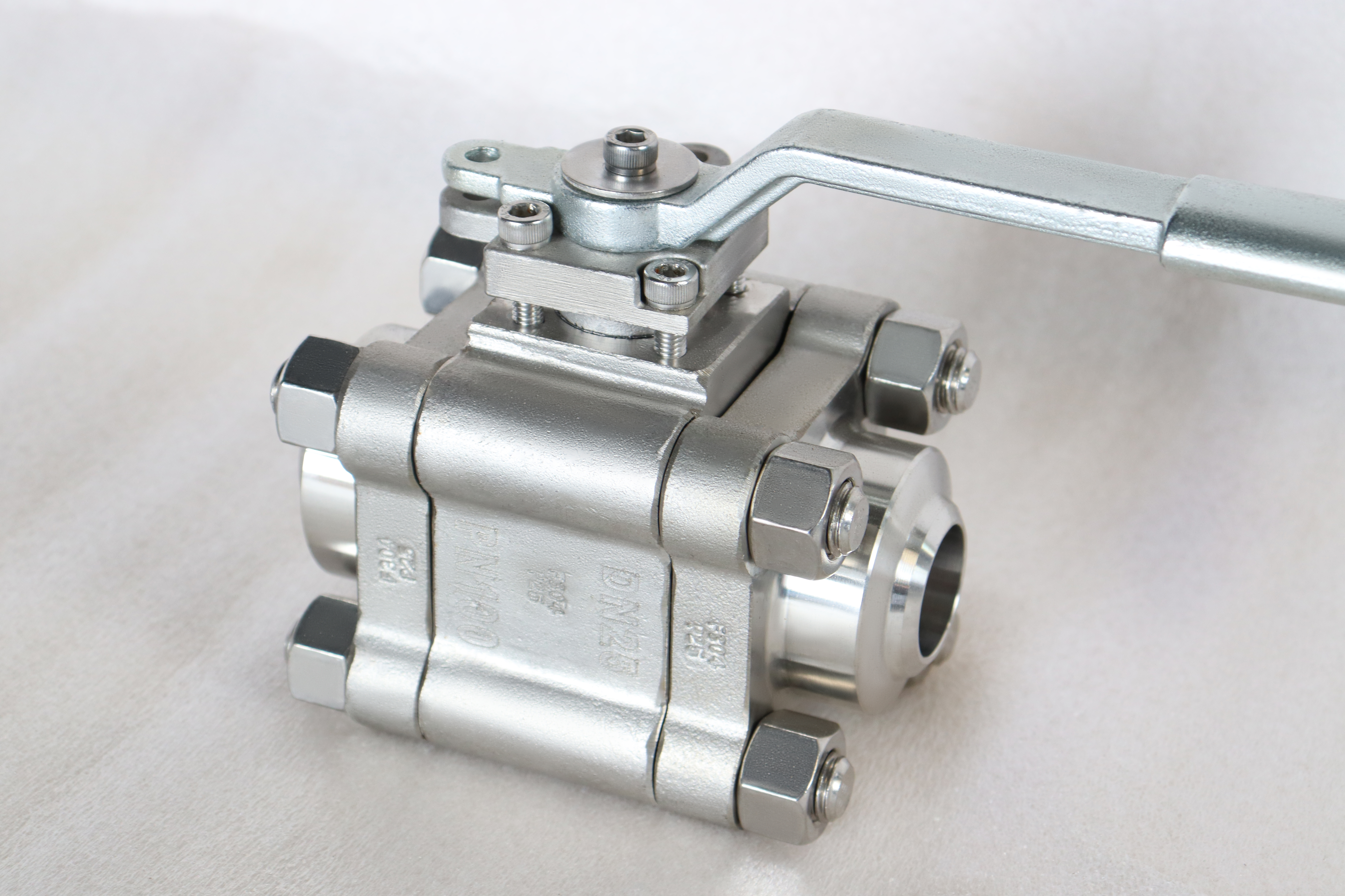
The name on this page contains a claim that deserves checking. High pressure, in the range that follows it, means Class 150 to Class 600, and the top of that range is PN 100. A valve at PN 100 is a serious valve and it is not high pressure in the sense that a Class 2500 valve is high pressure, so the word is doing marketing work rather than technical work.
That is not a reason to avoid the product. It is a reason to say what the product is: a stainless steel floating ball valve that goes up to the point where the floating construction stops being the right answer, with butt weld ends available so that it can be welded into a line rather than bolted into it.
The build in the photograph is a one inch valve at PN 100 in F304, and the range on the page is half inch to eight inch from Class 150 to Class 600. Where the photograph and the range disagree, the photograph is a single build and the range is what can be supplied, and the difference between the two is worth knowing before an order is placed.
Design and Construction
The body is a bolted construction with a floating ball, and the ball seals on the downstream seat. There is no trunnion, so the ball is held by the two seat rings alone, and the pressure pushes it into the seat on the outlet side. That is the mechanism, and it is why a floating valve at this size is a one barrier valve.
The ends can be raised face flanged or butt weld, and the second option changes the valve's character rather than just its connection. A flanged valve can be unbolted and taken to a bench; a butt welded valve is part of the line from the day it is welded until the day the line is cut, so everything that would otherwise be fixed later has to be decided at the order.
The class that the photograph represents is worth putting in both conventions. PN 100 is the European designation and Class 600 is the American one, and API 6D clause 7.2 puts them in the same row of its table. A buyer who asks for PN 100 and receives a valve marked Class 600 has received the article that was ordered, and the reverse is also true.
The seat is a polymer insert at the standard build and can be a metal seat as an option. That option changes the temperature ceiling and the leakage acceptance at the same time, so it is a decision about the duty rather than an upgrade, and a metal seat on a floating valve is a different valve with a different set of expectations.
The stem is retained from inside the body and the gland sits above it, with a lever keyed to a flatted stem end. At one inch the lever is the natural operator, and an actuator is fitted where the valve is automated rather than where the torque demands it.

Material Options
The parameter list says 316 for the body, the ball and the stem, and the photograph is named for a F304 build. Those two statements are not the same, and on a stainless valve the difference matters because 304 and 316 behave differently in chloride service. The grade should be confirmed on the plate rather than assumed from the page.
| Component | Stated Build | Option | What It Decides |
|---|---|---|---|
| Body | 316 stainless | 304 where the medium allows | Chloride resistance of the pressure boundary |
| Ball | 316 stainless | 304 | Corrosion at the sealing surface |
| Stem | 316 stainless | 304 | Stem corrosion and strength |
| Seat | PTFE or reinforced PTFE | Metal seat for temperature | Temperature ceiling and leakage acceptance |
| Packing | PTFE chevrons | Graphite where temperature requires | Stem seal |
| Body gasket | Spiral wound | PTFE envelope for chemical service | The body joint |
| Ends | Raised face flange | Butt weld to ASME B16.25 | Whether the valve can ever be removed |
| Operator | Lever | Actuator | Manual or automated duty |
The molybdenum in 316 is what separates it from 304 in a chloride environment, and it is the only difference that matters for most buyers. A 304 body in a chloride duty will pit and a 316 body in the same duty will not, and the two are visually identical and are frequently confused on a delivery. That is why the plate, the certificate and the material identification record are read together rather than any one of them on its own.
The metal seat option is worth understanding before it is chosen. A metal seat on a floating valve is a lapped pair accepted at a leakage rate, and the floating construction gives it less support than a trunnion would, so a metal seat here is a compromise for temperature rather than a performance upgrade.
Technical Specifications
The range is half inch to eight inch from Class 150 to Class 600, and the class designations map to PN 20 through PN 100 in API 6D clause 7.2. The photographed build is at the top of that range, which makes it the most demanding combination the page offers rather than a typical one.
| Item | Value |
|---|---|
| Size range | Half inch to eight inch, DN 15 to DN 200 |
| Pressure class | Class 150 to Class 600, PN 20 to PN 100 |
| Body style | Bolted body, floating ball |
| Body material | 316 stainless, 304 where specified |
| Seat | PTFE, reinforced PTFE or metal |
| Ends | Raised face flange to ASME B16.5, butt weld to B16.25 |
| Face to face | ASME B16.10 for the size and class, confirmed on the drawing |
| Temperature | Minus 46 to plus 200 C, insert limited |
| Operator | Lever, or actuator per order |
| Test | API 598 shell and seat, a result per seat |
| Fire test | API 607 where specified |
The temperature range is stated as minus 46 to plus 200 C and it is the range of the insert rather than of the body. That is a more honest figure than the wide ranges on some pages, because it describes what the valve will actually do rather than what the steel would survive if the seat were removed.
Standards and Compliance
Two product standards are named on the page and both apply across this range, which is one of the few places where that is straightforward. API 6D covers the whole of it and API 608 covers DN 15 to DN 600 in Class 150 to Class 600, so every size and class here is inside both.
| Requirement | Document | What It Means Here |
|---|---|---|
| Wall and rating | ASME B16.34 | Rating by class and material group |
| Product requirements | API 6D | Design, marking, documentation |
| Product requirements | API 608 | Also covers this range |
| Butt weld ends | ASME B16.25 | Bevel and bore match to the pipe |
| Flange dimensions | ASME B16.5 | Raised face, size specific bolt circle |
| Pressure test | API 598 | Shell 1.5 times, seat 1.1 times |
| Fire test | API 607 or ISO 10497 | Type test where specified |
| Material certificate | EN 10204 3.1 | Heat number matched to the plate |
The butt weld standard is the one that needs attention when that end is ordered, because a weld end is specified by the pipe it will meet rather than by the valve. The bevel, the bore and the wall at the end all have to match the pipe schedule, and a valve welded to a heavier schedule than its ends were machined for leaves a step inside the line that no test will find.
Manufacturing Process
The body is machined from a casting or a forging depending on the size and the works, and the seat pockets and the flange faces are cut from one reference per part. On a bolted body the two halves have to close with the seat pockets in line, and that alignment is what the machining reference is for.
The body joint is the operation that separates a bolted body from a welded one in the works, because the two halves are machined as a pair and then kept together through assembly. On a welded body the halves are joined permanently and the machining has to be completed before the join; on a bolted body the joint faces are cut and then the two halves are brought back together with a gasket between them, which is why the joint faces are the most closely toleranced surfaces on the part.
The ball is machined and ground, and on a soft seated valve the finish of the sphere is what the insert conforms to. A ball ground to a sphere will take a contact band all the way round; a ball polished to look right but out of round will seal on part of the circumference and leak on the rest.
The weld ends are the operation that differs from a flanged valve. The bevel is machined to the pipe schedule and the bore is matched to it, and the end is left clean and dry because it will be welded in place and anything on it becomes an inclusion in the weld.

Quality Control and Testing
The shell test on a small valve is quick and it is easy to do badly. A one inch body reaches test pressure almost instantly, so the hold time is what proves the joint rather than the pressure reading, and a works that fills, pressures and releases in a few seconds has not tested anything except that the body does not burst. The hold should be long enough to watch the joint, and the record should show that it was.
The identity check on a stainless valve is the one that finds the most substitutions, because 304 and 316 look the same and pass the same pressure test. A portable analyser separates them on molybdenum in a few seconds, and on this valve it should be applied to the body, the ball and the stem.
| Step | Check | Acceptance |
|---|---|---|
| 1 Incoming | Heat number against the mill certificate | Grade chemistry as ordered |
| 2 Identity | Positive material identification on body, ball, stem | Molybdenum present where 316 was ordered |
| 3 Weld ends | Bevel angle, bore and wall against the pipe schedule | ASME B16.25 |
| 4 Machining | Seat pocket alignment across the joint | Drawing tolerance |
| 5 Shell test | Body and joint at 1.5 times | API 598, no leakage |
| 6 Seat test | Each seat at 1.1 times, cavity vented | API 598, no visible leakage |
| 7 Torque | Lever torque at rated pressure | Drawing figure |
| 8 Final | Ends capped, faces masked, marked, crated | Works standard |
The weld end check is the one that cannot be done after the valve is installed. A bevel that does not match the pipe schedule produces a root gap that the welder has to fill with wire, and the result is a joint that passes radiography and has a step inside it where the bore changes.

Applications and Industry Service
Stainless floating valves at this class are bought for the small bore side of a plant where the medium would attack carbon steel and the pressure is real but not extreme. Chemical dosing lines, demineralised water, food and beverage service, pharmaceutical process lines and the isolation around instruments in a corrosive area.
The butt weld option is bought where the joint has to be permanent, which is normal on high purity service and on lines where a flanged joint is a leak point that nobody wants to maintain. That is a different product decision from the valve itself, and it should be made at the enquiry rather than by the piping contractor.
The valve is the wrong answer where the pressure is genuinely high, because the floating construction tops out around Class 600 and above that the trunnion valve is the right article. It is also the wrong answer where the temperature is above the insert limit, where a metal seat or a different valve entirely is needed.
Installation, Operation and Maintenance
A flanged valve of this kind installs like any other: flanges brought up parallel, the right gasket for the size and class, and the body supported so the joint is not carrying pipe load. The only difference on a stainless valve is that the studs should match the body rather than the pipe.
A butt welded valve is welded with the ball in the open position and the body protected from the heat, and the weld is cooled before the valve is cycled. Welding heat into a valve with a polymer seat in it is the fastest way to destroy the seat before the line is ever pressurised.
For maintenance on a flanged valve the line is isolated, vented and drained, the cap studs are released in a pattern, and the cap comes away with one seat. On a welded valve the same work is a line cut, which is why the seat and the grade should be right at the order.
How to Specify and Order
Six lines fix the valve: size, class, body grade, seat, end type and operator. Two more belong on the order and are often left off: the pipe schedule for a weld end, and the grade of the ball and stem separately from the body, because stainless in the body line does not specify the trim.
Four questions belong to the line rather than to the valve: the medium and its chloride content, the design temperature, the design pressure and whether the valve will ever need to be removed. The first decides 304 or 316, the second decides the seat, the third confirms the class, and the fourth decides between flanged and welded ends.
Documents to name in the order: the EN 10204 3.1 certificate with the heat number matched to the plate, the material identification record for the body and the trim, the weld end dimensional record against the pipe schedule, the shell and seat test record with a result per seat, and the drawing carrying the face to face dimension.
FAQ
Q: Is PN 100 high pressure?
A: Not by the scale the word implies. PN 100 sits at Class 600, and the range on this page stops there, where a Class 2500 valve is still two steps above it. The name is doing marketing work rather than technical work, and a buyer who reads high pressure as 2500 class will be surprised by what arrives. What the page does offer is the top of the floating construction, which is a real limit.
Q: What changes when the ends are butt weld?
A: The valve stops being a component and becomes part of the line. A flanged valve can be unbolted and taken to a bench for a seat change, and a welded one has to be cut out, so everything that would otherwise be settled later, the seat insert, the body grade and the face to face dimension, is settled at the order. That is the whole difference and it is decided by one line on the data sheet.
Q: Why is F304 in the photograph when the source lists 316?
A: Because the photograph is the authority on the build and the parameter line is a range. The image file names this valve as DN25 at PN 100 in F304, and the body in the picture is a single build rather than the whole list. Where the two disagree this page follows the picture and says so, and a 316 body is available on request.
Q: Can the seat be metal at this class?
A: It can be offered, and it is rarely the right answer here. A metal seat is bought when the temperature or the medium will not allow a polymer, and at PN 100 the temperatures that need it are usually beyond what the body grade is comfortable with as well. If a metal seat is needed, the class is usually higher and the construction is a trunnion rather than a floating valve.
Q: Why does the floating design stop at eight inch?
A: Because the whole pressure load goes into the downstream seat and the operator has to overcome the friction that load creates. That friction grows with the bore and with the pressure together, so at eight inch the lever becomes a gear and above eight inch the trunnion takes over and carries the load in the body instead of in the seat.



Hot Products


News
Why A Ball Valve Gets Harder To Turn: Five Causes, And The Test That Tells Them Apart
A ball valve that stiffens over months points at one of five parts. Measure torque with the line pressurised and again vented, and the split becomes visible.
Read More
The Ball Valve at Four Thousand Bar: Seat Load, Erosion And Fatigue in Waterjet Circuits
At 4,000 bar a 10 mm bore puts 31 kN on the seat and a 0.1 mm leak cuts steel. What a ball valve must survive in a waterjet or intensifier circuit.
Read More
Large Diameter Ball Valves: Four Limits That Change The Design
Above a certain size a ball valve stops being a scaled one. Ball weight, operator torque, body split and the test bench each set a limit at a different size.
Read More
Cast Or Forged Ball Valve Body, And What A Radiography Acceptance Level Actually Buys You
Casting or forging is only half the decision. What RT, UT, MT and a proof test each find in a ball valve body, and where the geometry defeats all of them.
Read More