

CHINA J-VALVES Offers Various High-quality I ndustrial Ball Valves
J-VALVES, a distinguished professional ball valve manufacturer rooted in China, takes pride in its extensive product portfolio. Our offerings span a wide range, including trunnion-mounted ball valves, floating ball valves, high-temperature ball valves, high-pressure ball valves, metal-sealed ball valves, ultra-low temperature ball valves, DBB ball valves, Three-way And Four-way Ball Valve, and fully welded ball valves. Each product is a testament to our commitment to precision engineering and reliable performance. Meticulously crafted, they are designed to not only meet but exceed the most stringent industrial demands, ensuring stable operation even under extreme conditions. This enables us to provide our clients with high-value services and makes our valves widely sought-after in industries.
Product Category
Contact Us


-
J-VALVES-Q41F
-
J-VALVES
Overview of the J-VALVES 3 inch 600LB WCB two piece floating ball valve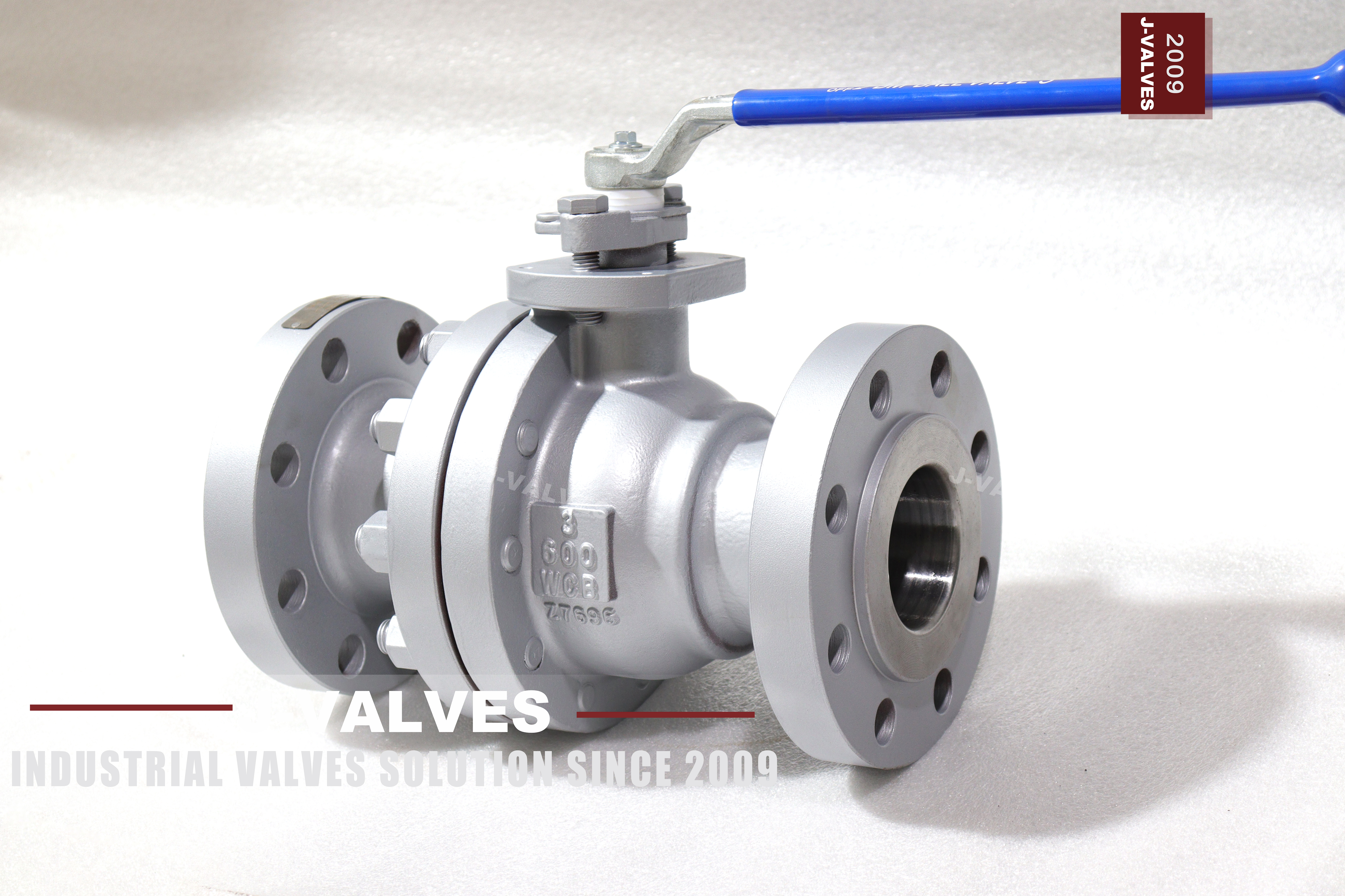
The ball in this valve is not held in place. It sits loose in the cavity between two seats with only the stem above it, and when the line comes up to pressure the pressure itself lifts the ball off its centreline and pushes it downstream into the seat on the outlet side. Nothing else locates it. That is the entire sealing mechanism of a floating ball valve, and once it is stated that way, most of the arguments about this body style answer themselves.
What follows from the mechanism is worth spelling out, because it is misread on a lot of data sheets. A floating ball seals on one seat at a time: the downstream seat, the one the ball is being pressed into. The upstream seat is loaded only by its own spring and by whatever preload was set at assembly, and while the downstream seat is holding, the upstream seat is not a barrier at all. The valve is bidirectional in the sense that it will seal whichever way the pressure arrives, because the ball simply moves the other way. It is not a double block and bleed valve, and it is not a double barrier valve, and no amount of paperwork will make it one.
The valve is three inch at Class 600 in cast carbon steel. In group 1.1 of ASME B16.34 the class reads 1480 psi at 38 C, and API 6D clause 7.2 records the same class as PN 100. The body is cast ASTM A216 WCB, the ends are raised face flanges to ASME B16.5, the port is full, and the operator is a lever.
The photographs show a two piece bolted body, a lever on a squared stem, and a flange face that has been machined and then masked for shipment. What they do not show is the part that decides whether the valve works: the seat, the spring behind it, and the clearance between the ball and the body cavity that lets the ball travel far enough to reach the seat in the first place.
Design and Construction
The body is in two pieces, a main body and one end cap, closed on a single ring of studs with a single gasket between them. That is one joint at full line pressure instead of the two a three piece body would have, and it is the commercial reason this style is bought at three inch. It is also the reason the maintenance access is one sided: the cap comes off and exposes one seat and the ball, while the other seat stays in the main body.
The ball is a sphere with a full port through it, and it is supported only by the two seats. There is no trunnion above or below it, which is the definition of the floating construction and the reason the body can be shorter and the parts fewer than on a trunnion valve of the same size.
The seat arrangement on a floating valve can only be the single piston effect pattern. The double piston effect and the two combined arrangements that appear in the catalogue are trunnion constructions, because they need a seat with an independent piston area that line pressure can act on from behind. A floating ball has no such area: the seat is a ring in a pocket with a spring behind it, and the pressure that loads it comes through the ball rather than around it. Anyone who asks for a double piston effect seat on a three inch floating valve is asking for a part that does not exist in this construction.
The cavity between the seats is where the pressure ends up when the valve is closed and the line is hot, and on this construction the cavity relieves to the upstream side through the seat that is not sealing. That is why the body does not need a separate self relieving arrangement and why the single cavity plug on the body is a drain rather than a safety device.
The stem enters through the body and is retained by a shoulder on the inside, so it cannot be blown out by pressure from below. The gland sits on top and compresses the packing, and the lever is keyed to a squared or flatted stem end. At three inch the lever is still the right operator: the hand force needed is within what one person can apply, and the quarter turn is short.

Material Options
ASTM A216 WCB is cast carbon steel and at Class 600 in this size it is the correct economical choice for water, steam, dry gas and hydrocarbon liquids that are not corrosive. Its two limits are corrosion and low temperature, and both are answered by changing the casting grade rather than by adding wall thickness, because the wall is set by the class and not by the duty.
| Component | Standard Build | Options | What It Decides |
|---|---|---|---|
| Body and cap | ASTM A216 WCB | CF8 or CF8M cast stainless | Corrosion and low temperature limit |
| Ball | WCB with hard chrome | CF8 or CF8M stainless, or 316 with hard facing | Whether the seat stays clean |
| Seat | PTFE or reinforced PTFE | PPL for higher temperature | The temperature ceiling of the whole valve |
| Stem | 316 stainless | 17-4PH | Lever torque and stem life |
| Packing | PTFE or flexible graphite | Graphite with an anti-extrusion ring | Stem seal at temperature |
| Body gasket | Spiral wound, graphite filled | PTFE envelope | The single joint at full pressure |
| Bolting | A193 B7 with A194 2H | B8M with 8M | Thermal match with the body |
| Cavity plug | Steel plug with sealing compound | Needle valve | Whether the cavity can be drained |
The seat is the part that sets the temperature ceiling of the whole valve, and it is worth being explicit about it at Class 600. PTFE is the standard insert and it is what makes the valve bubble tight at ambient and at moderate temperature. Above the point where the insert starts to deform permanently, the answer is a different insert rather than a different body, and the body does not change at all.
A stainless ball in a carbon body is the upgrade that gets bought most often on a valve of this class, and the reason is usually the medium rather than the pressure. A carbon steel ball with a chromium coating is fine in clean water and clean gas, and it is the part that suffers first when the medium carries fines or when the valve sits closed for long periods with dirty product on the seat.
Technical Specifications
Class 600 sits at the point on the carbon steel ladder where the wall is no longer nominal and the joint has to be treated as a pressure boundary in its own right. The class is PN 100 under API 6D, and the group 1.1 rating is 1480 psi at 38 C, which is the figure that governs the shell test rather than the figure the line will ever see.
| Item | Value |
|---|---|
| Size | Three inch, DN80 |
| Pressure class | Class 600, recorded as PN 100 in API 6D clause 7.2 |
| Body style | Two piece bolted body, floating ball, full port |
| Body material | ASTM A216 WCB, ASME B16.34 group 1.1 |
| Rating | 1480 psi at 38 C in group 1.1 |
| Flange | ASME B16.5 Class 600, raised face |
| Face to face | ASME B16.10 for NPS 3 Class 600, confirmed on the signed drawing |
| Seat design | Single piston effect only, spring loaded |
| Temperature | Minus 29 to plus 425 C as a body figure, insert limited |
| Operator | Lever as photographed; gear or actuator per order |
| Test | API 598 shell and seat, each seat proved separately |
| Product standard | API 608 and API 6D both apply at this size and class |
The floating build in this range runs from half inch to eight inch, and three inch sits comfortably inside it. Above that the same body style is normally supplied trunnion mounted, not because the floating construction stops sealing but because the force needed to turn a ball of that size against two loaded seats stops being a force one person can apply with a lever.
Standards and Compliance
Two product standards apply at three inch Class 600, and they apply together rather than one excluding the other. API 608 covers valves from DN 15 to DN 600 in Class 150 to 600, and API 6D covers pipeline valves across a wider class range. A three inch Class 600 valve is inside both, so a data sheet that names only one of them is incomplete rather than wrong.
| Requirement | Document | What It Means Here |
|---|---|---|
| Wall thickness and rating | ASME B16.34 group 1.1 | 1480 psi at 38 C |
| Flange dimensions | ASME B16.5 Class 600 | Raised face, three inch bolt circle |
| Face to face | ASME B16.10 for NPS 3 | The dimension the spool is built to |
| Pressure testing | API 598 | Shell 1.5 times, seat 1.1 times |
| Fire test | API 607 or ISO 10497 | Type test, certificate scope to be read |
| Material certificate | EN 10204 3.1 | Heat number matched to the plate |
| Anti-static | API 608 and API 6D both require it | Continuity from ball to body |
| Marking | API 6D | Size, class, material, heat, standard |
The face to face dimension is tabulated by NPS 3 at Class 600 in ASME B16.10, and it is the number the pipe spool is built to. It should be confirmed on the signed general arrangement drawing rather than taken from a catalogue, because the tabulated figure is the minimum and a casting can be longer.
Manufacturing Process
The body and cap are cast, then machined in one setting per part so that the flange face, the bolt circle, the joint face and the seat pocket are all referenced to the same centreline. That reference is what makes the two halves close without the seat pockets going out of alignment, and it is the operation that separates a body that seals from one that weeps at the joint no matter how the studs are torqued.
The ball is machined and then ground, and the spherical surface is the sealing surface, so it is finished to a sphericity the seat insert can conform to rather than to a surface roughness number alone. The seat ring is machined with the insert pocket, and the spring behind it is selected so that the seat preloads the ball at low pressure, before line pressure has anything to push against.
Assembly is gasket, ball, both seats, cap, then studs brought up in a cross pattern to the drawing figure. The lever and the stop plate go on last, and the stop is set so that the port is fully open and fully closed at the two extremes of travel rather than a few degrees short of either.

Quality Control and Testing
The heat number is stamped on the body and repeated on the certificate, and it is the first thing checked on receipt because it is the only thing that ties the casting in front of you to the chemistry that was tested. On a carbon body the identity check is as much about excluding a mixed part from another grade as about confirming WCB.
| Step | Check | Acceptance |
|---|---|---|
| 1 Incoming | Heat number against the mill certificate | A216 WCB chemistry and tensile |
| 2 Identity | Positive material identification | Grade match, no mixed parts |
| 3 Machining | Seat pocket alignment across the joint | Drawing tolerance |
| 4 Dimensional | Flange facing, bolt circle, face to face | ASME B16.5 and B16.10 |
| 5 Shell test | Body and the joint at 1.5 times | API 598, no leakage |
| 6 Seat test | Each seat at 1.1 times, cavity vented | API 598, no visible leakage on a soft seat |
| 7 Torque | Lever operating torque at rated pressure | Within the figure on the drawing |
| 8 Final | Cavity drained, faces masked, marked, packed | Works standard |
The seat test on a floating valve is where the construction shows up in the records. Each seat has to be proved with the cavity vented, because with the cavity open only the seat facing the test pressure is being loaded by the ball. A test that pressurises the whole cavity proves the shell and proves nothing about which seat is holding.

Applications and Industry Service
Three inch Class 600 in carbon steel is a utility and process valve. It is bought for water and steam headers, for plant air and nitrogen, for fuel gas and for hydrocarbon liquids that are clean enough not to attack a carbon body. In all of those duties the requirement is a tight shutoff that can be restored by replacing one seat, and the floating construction delivers that with the fewest parts of any body style.
It is the wrong valve in three situations, and they are worth naming because each one gets discovered late. The first is double block and bleed, where two independent barriers are required and a floating ball only ever provides one. The second is a line that has to be pigged or swept, where a full port helps but where the seat and cavity are still a trap. The third is a duty with a very high cycle count, where the seat insert takes the wear and the interval between seat changes becomes the maintenance plan.
Steam service is where the seat choice matters most, and it is the question that should be settled before the valve is ordered rather than after. Saturated steam at Class 600 pressure is a temperature problem for a PTFE insert even though it is not a pressure problem for a WCB body, and the answer is a different insert in the same body.
Installation, Operation and Maintenance
The valve can be installed in either direction, because the ball moves to whichever seat the pressure is behind. What does change with orientation is the cavity plug and the drain point, and on a line that will be drained for maintenance the plug should end up at the lowest point rather than at the top where it was convenient to reach.
Bring the mating flanges up parallel before tensioning anything, and use the gasket and the studs that belong to the three inch Class 600 flange rather than hardware sized to the bore. A flange pulled into place by the studs will distort the cap joint, and the joint will weep at test pressure with the gasket taking the blame for a piping error.
For maintenance the line is isolated, vented and drained through the cavity plug, the cap studs are released in a pattern, and the cap comes away with one seat. Both seats should be replaced as a pair even though only one was leaking, because the two have seen the same number of cycles and the second one is halfway through its life. The gasket is replaced rather than reused, and the studs go back to the drawing figure in a cross pattern.
How to Specify and Order
Six lines fix the valve: size, class, body grade, seat insert, flange facing and operator. On a floating valve there is a seventh that is easy to leave out and hard to fix later, which is the direction of shutoff required, because a valve bought for bidirectional sealing and then applied to a double block and bleed duty will be a warranty argument rather than a valve.
Four questions belong to the line rather than to the valve: the medium, the design temperature, the design pressure, and the cycle count expected over the life of the plant. The medium decides the ball and body grade, the temperature decides the seat insert and therefore the whole temperature rating, the pressure confirms the class, and the cycle count decides whether a floating seat is the right wear part or whether the duty belongs on a trunnion valve.
Documents to name in the order: the EN 10204 3.1 certificate with the heat number matched to the plate, the shell and seat test record showing each seat proved separately, the fire certificate if one is required with its scope read rather than assumed, and the general arrangement drawing carrying the face to face dimension the spool will be built to. The seat test record is the one that settles an argument about tightness, because it is the only document that shows which seat was tested against which pressure.
FAQ
Q: Does a floating ball valve seal on both seats at once?
A: No. The ball is free to move, so line pressure pushes it into the downstream seat and that seat does the sealing. The upstream seat is loaded by its spring and its preload only. The valve will seal whichever way the pressure arrives, because the ball simply moves the other way, but only one seat is a barrier at any moment.
Q: Can this valve be used for double block and bleed?
A: No. Double block and bleed needs two independent barriers, and a floating ball never provides two. A valve specified for DBB duty has to be a trunnion construction with double piston effect seats, where both seats are barriers and the cavity can be bled between them.
Q: Can a floating valve have a double piston effect seat?
A: Not in this construction. Double piston effect needs a seat with an independent piston area for line pressure to act on from behind, and a floating ball has no such area. The seat arrangements listed for DBB service in the catalogue are trunnion constructions, and they cannot be transferred to a floating body.
Q: Why prove each seat separately at the works?
A: Because with the cavity vented only the seat facing the test pressure is loaded by the ball. Pressurising the whole cavity proves the shell and proves nothing about which seat holds, so the test record for this valve should show two seat results rather than one.
Q: What limits the temperature of this valve?
A: The seat insert, not the body. The WCB body figure runs to 425 C, but a PTFE insert sits well below that. Above the insert limit the answer is PPL or a metal seat in the same body rather than a different body.


Hot Products


News
Reading A Ball Valve GA Drawing: The Five Dimensions That Decide Whether It Fits
A GA drawing is approved for its outline and lost on its section. The five dimensions that decide whether the valve fits, bolts and can be operated.
Read More
Stainless Steel Ball Valve Grades: 304, 316 And 316L, And What Actually Decides
Molybdenum is the difference that decides the duty, carbon is the difference that gets missed, and the chloride in the line matters more than the price.
Read More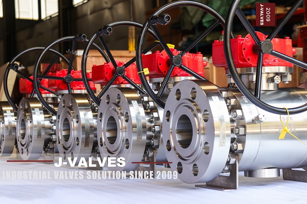
Ball Valve Spare Parts for Overseas Projects: The Wear Part List, The Quantity Math, And Four Traps
Why isolation valves fail on calendar time, not cycles. Wear part lists, Poisson stock maths, seat kit traps and the clauses that decide year six.
Read More
Ball Valves On A Bottom Loading Gantry: Creep, Dry Break And The Test That Proves Neither
A loading gantry cycles a ball valve far more than it is designed for and still cannot prove shut-off. Where creep starts, and what to specify.
Read More