


CHINA J-VALVES Offers Various High-quality I ndustrial Ball Valves
J-VALVES, a distinguished professional ball valve manufacturer rooted in China, takes pride in its extensive product portfolio. Our offerings span a wide range, including trunnion-mounted ball valves, floating ball valves, high-temperature ball valves, high-pressure ball valves, metal-sealed ball valves, ultra-low temperature ball valves, DBB ball valves, Three-way And Four-way Ball Valve, and fully welded ball valves. Each product is a testament to our commitment to precision engineering and reliable performance. Meticulously crafted, they are designed to not only meet but exceed the most stringent industrial demands, ensuring stable operation even under extreme conditions. This enables us to provide our clients with high-value services and makes our valves widely sought-after in industries.
Product Category
Contact Us


-
J-VALVES-Q41F
-
J-VALVES
Overview of the J-VALVES half inch 300LB floating ball valve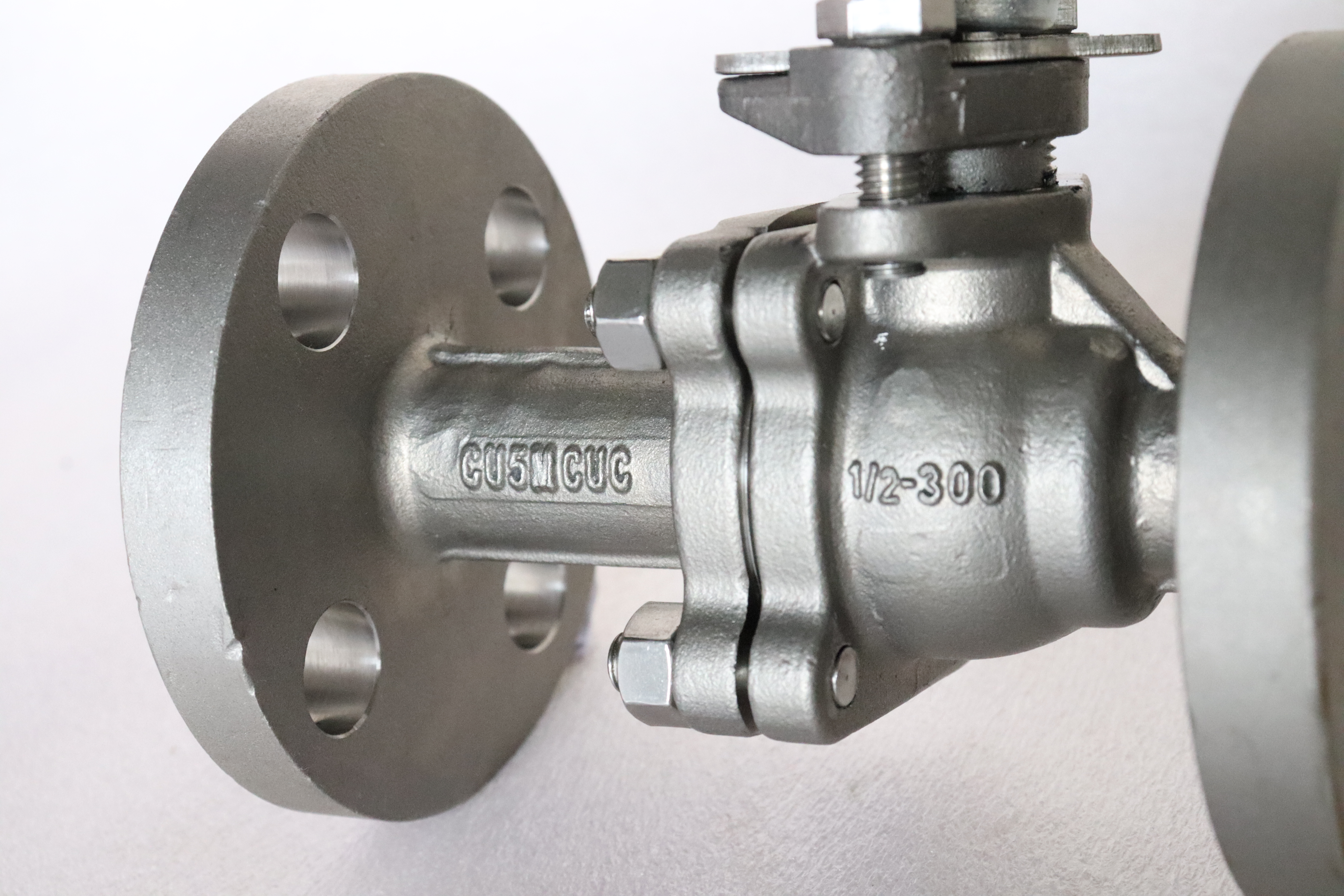
Half an inch at Class 300 is the smallest valve in the forged range and the one where the least of the engineering is in the body. The body is small, the ball is small, and the whole assembly weighs less than the spanner used to install it. What is not small is the number of ways the same body can be terminated, and that is what decides whether the valve is right for a line.
The same casting or forging is offered with tapered threads, parallel threads, socket weld ends, butt weld ends and flanges. Each of those is governed by a different standard, each has a different joint quality, and none of them is interchangeable with another. A buyer who specifies the size and the class and leaves the end to the supplier has specified perhaps half of the valve.
The class itself is worth a word, because at this size it is usually a compatibility decision rather than a pressure one. Class 300 puts the body in group 1.1 of ASME B16.34, where the rating is 740 psi at 38 C, and a half inch line rarely runs anywhere near that. The class is quoted because the piping specification says 300, because the flange or the fitting either side is 300, and because a mixed bill of materials is a maintenance problem later.
The valve in the photographs is the flanged variant: a two piece body, four bolt flanges, a floating ball and a long lever. The plate on the body reads the size and the class, and the rest of the identification is a cast code rather than a grade.
Design and Construction
The body is two pieces, a main body and a cap, closed by four bolts on this size. The cap carries one seat and one end connection, the main body carries the other seat and the stem. That is the smallest sensible split for a valve that has to be repairable, and at half an inch it is also the cheapest: four bolts, one gasket, and the whole interior is exposed.
The ball floats. It is not carried on trunnions, and at this size there is no reason for it to be: the force that pressure puts on a half inch ball is small enough that the seat can take it directly, which is what makes a floating design self energising rather than merely adequate. Pressure pushes the ball into the downstream seat and the seal gets tighter as the pressure rises.
The stem is packed and held by a bolted gland under the lever. On a valve this small the gland is a nut or a small bolted plate, and the packing is a few rings of PTFE or graphite. The lever usually carries a locking device so the valve can be held in position, which matters on an instrument line where vibration will otherwise walk a lever round.

Material Options
The body is available as a forging in A105N carbon steel, in A182 F304 or F316 stainless, or in A350 LF2 for low temperature service. At this size the stainless option is common even on a carbon line, because a half inch valve is often bought for a corrosive sample point or a chemical injection line where the surrounding pipe is stainless.
The ball and seats follow the same logic. A stainless ball in a carbon body is normal; a carbon ball with electroless nickel is the economy option for clean, dry service. Seat material sets the temperature, and at this size the seat is small enough that a metal seated variant is unusual but available for hot or abrasive duties.
| Component | Standard Build | Options | What It Decides |
|---|---|---|---|
| Body and cap | ASTM A105N forging | A182 F304 or F316, A350 LF2 | Corrosion and temperature |
| Ball | A182 F304 or F316 | A105N with electroless nickel | Bore cleanliness |
| Seat | PTFE or reinforced PTFE | PPL, metal seat | The temperature ceiling |
| Stem | A182 F316 | 17-4PH | Wear at the gland |
| Packing | PTFE | Flexible graphite | Stem seal at temperature |
| Body joint gasket | Spiral wound or PTFE envelope | Graphite filled | The single joint at line pressure |
| Bolting | A193 B8 with A194 8 | B7 with 2H for a carbon body | Thermal match with the body |
| End connections | Threaded, socket weld, butt weld, flanged | Per the piping specification | The joint quality, which is the real variable |
A stainless body with stainless trim is the version to buy where the medium is uncertain, because at this size the price difference is small compared with the cost of replacing a valve that corroded at a sample point nobody was watching.
Technical Specifications
Class 300 is recorded as PN 50 in API 6D clause 7.2, and the size is half inch nominal, which is DN15. The bore through the ball is close to the pipe bore on a full port build, and slightly smaller where the valve is supplied reduced port for a higher pressure class in the same body.
| Item | Value |
|---|---|
| Size | Half inch, DN15 |
| Pressure class | Class 300, recorded as PN 50 in API 6D clause 7.2 |
| Body style | Two piece body, floating ball |
| Body material | ASTM A105N, or A182 F304 or F316 |
| Rating | 740 psi at 38 C in group 1.1 |
| End connections | NPT or G thread, socket weld, butt weld, or ASME B16.5 flange |
| Thread standard | ASME B1.20.1 for NPT, ISO 228 for G |
| Weld end standards | ASME B16.11 for socket weld, ASME B16.25 for butt weld |
| Flange standard | ASME B16.5 Class 300, four bolt |
| Face to face | ASME B16.10 for the end type ordered, confirmed on the drawing |
| Temperature | Minus 29 to plus 425 C as a body figure |
| Operator | Lever with locking device as photographed |
| Product standard | API 608 and ASME B16.34; API 6D where specified |
The face to face line needs a caveat that applies to every small valve: the dimension depends on the end type as well as the size. A threaded valve and a flanged valve of the same nominal size are different lengths, and a socket weld valve differs again. The ASME B16.10 table covers the flanged and weld end valves; a threaded valve is often built to a manufacturer's standard length, so the drawing is the only safe source.
Standards and Compliance
API 608 applies here and there is no ambiguity about it: half inch at Class 300 is inside the DN 15 to DN 600 and Class 150 to 600 scope of the document. ASME B16.34 supplies the wall and rating, and it is the document that turns the class into a pressure at a temperature.
The end connections bring their own standards, and this is where a small valve generates more paperwork than its size suggests. NPT threads are ASME B1.20.1, G threads are ISO 228, socket weld ends are ASME B16.11, butt weld ends are ASME B16.25, and flanges are ASME B16.5. A valve cannot be built to all of them at once, and the order has to name one.
| Requirement | Document | What It Means Here |
|---|---|---|
| Wall thickness and rating | ASME B16.34 group 1.1 | 740 psi at 38 C in group 1.1 |
| Product standard | API 608 | Applies: DN 15 at Class 300 is in scope |
| Taper pipe thread | ASME B1.20.1 | The joint standard for an NPT end |
| Parallel pipe thread | ISO 228 | The joint standard for a G end |
| Socket weld ends | ASME B16.11 | Socket depth and bore step are standardised |
| Butt weld ends | ASME B16.25 | Weld prep geometry is standardised |
| Flange | ASME B16.5 Class 300 | Four bolt pattern at half inch |
| Pressure testing | API 598 | Shell 1.5 times, seat 1.1 times |
Manufacturing Process
The body starts as a forging or from bar stock, depending on the size and the shape, and at half inch both routes are practical. The forging route gives a part with grain following the shape and a consistent wall; the bar route gives a part that is machined from solid with no draft angles to worry about. Either way the body is machined all over, and the ends are cut last.
Threads are cut or rolled, and the choice matters more than it sounds. A rolled thread has a burnished flank and a better fatigue life; a cut thread is easier to keep within gauge on a small diameter. Either way the thread is checked with a plug or ring gauge rather than by eye, because an NPT thread that starts easily and leaks at pressure is the classic small valve failure.
Assembly is quick and unforgiving. The gasket goes in dry, the four bolts come up in a cross pattern, the stem is packed and the gland is set so the lever turns without binding, and the valve is tested. On a valve this size the test is short, but a leak at the body joint or the gland is just as much of a leak as on a twenty inch valve.
Where the body is stainless the surface has to be restored after machining and before assembly. A cast or forged 304 body that has been machined, ground and handled with carbon steel tooling will show rust at the ends within weeks of installation, and the fault is contamination rather than grade. Pickling and passivation, and a bench kept separate from carbon work, are what prevent it.

Quality Control and Testing
Thread gauging is the check that distinguishes a good small valve from a bad one, and it is the one a buyer never sees. A taper thread is checked with a ring gauge for hand tight engagement and for the position of the gauge face; a parallel thread is checked with a ring gauge that must go and must not go past a limit. Neither check tells you anything about the body, and both are essential to whether the joint seals.
| Step | Check | Acceptance |
|---|---|---|
| 1 Incoming | Heat number against the mill certificate | A105N or the stainless grade ordered |
| 2 Threads | Ring gauge, hand tight engagement, gauge face position | ASME B1.20.1 or ISO 228 |
| 3 Weld ends | Socket depth, bore alignment, weld prep angle | ASME B16.11 or B16.25 |
| 4 Machining | Seat concentricity, joint face flatness | Drawing tolerance |
| 5 Shell test | Body and the single joint at 1.5 times | API 598, no leakage |
| 6 Seat test | Each seat at 1.1 times, cavity vented | API 598, zero visible on a soft seat |
| 7 Function | Quarter turn, lever lock, gland adjustment | Works standard |
| 8 Final | Bore dried, ends capped, thread protectors fitted | Works standard |
Thread protectors are not cosmetic. A small valve is shipped in a bag with other small valves, and a thread that has been knocked in transit will leak no matter how well it gauged at the works.

Applications and Industry Service
Half inch Class 300 is an instrument and utility size. Gauge roots, drain and vent connections, sample points, chemical injection lines, analyser systems, and the small isolation valves around a transmitter. In all of those the valve is there to isolate something small and awkward, and the class is there because the piping specification around it is 300.
It is also used as a maintenance valve on larger equipment, where a small isolation valve is needed at a sight glass, a level gauge or a filter housing. Those duties are hard on a valve in a way that pressure is not: they are operated rarely, often by hand on a cold morning, and the lever and the packing are what fail.
Instrument air and impulse lines deserve a note of their own, because the valve on the end of a gauge root is not chosen for its flow. It is chosen for how it behaves when someone closes it against a live transmitter and then opens it again without a pressure spike reaching the instrument. A slow quarter turn by hand is the whole requirement, and a lever long enough to give that control is worth more than a larger bore.

Installation, Operation and Maintenance
A threaded joint is made with a sealant that suits the service, applied to the male thread and not into the valve, and tightened to the point where the thread is engaged rather than as far as the arm will go. Over tightening a half inch valve splits the body at the thread, and the failure appears as a crack along the bore rather than as a leak at the joint.
A socket weld end needs the pipe inserted to the socket depth and the weld made without preheating a stainless body beyond what the procedure allows, because a small body heats fast. A butt weld end needs the bore aligned, since at this size a misalignment of a millimetre is a step in the flow path.
For maintenance the line is isolated and vented, the four cap bolts are released, and the cap, the seat and the ball come out as a set. On a valve this size the usual decision is whether to repair it at all: a new gasket and a new seat will restore it, and the labour is usually the larger part of the cost.
How to Specify and Order
Six lines fix the valve: size, class, body grade, end connection with its standard, seat material, and the lever or operator. The end connection is the one to write in full, because a purchase order that says half inch valve without saying NPT, G, socket weld, butt weld or flanged has not specified the valve at all.
Four questions are about the line: the medium, the temperature, the pressure, and whether the valve will be welded or screwed in. The medium decides the grade, the temperature decides the seat and packing, the pressure confirms the class, and the installation method decides the end.
Ask for the certificate with the heat number, the test record and, where the joint matters, the thread gauge report. On a small valve the gauge report is the only document that says anything about the part of the valve that will actually leak.
Thread protection is worth naming in the order as well. A valve shipped without caps on the ends will arrive with damaged threads or a damaged weld prep, and neither is repairable without re machining the end. On a valve this size that is the difference between a spare on the shelf and a part that has to be replaced.
FAQ
Q: Why specify Class 300 on a half inch valve?
A: Usually to match the piping specification rather than for the pressure. A half inch line rarely runs near the 740 psi the class allows at 38 C, but the flange or the fitting either side is already 300, and a mixed bill of materials becomes a maintenance problem later.
Q: Which end connection should be ordered?
A: The one the pipe is already prepared for. NPT and G are screwed, socket weld and butt weld are welded, and flanged bolts to an ASME B16.5 pattern. They are governed by four different standards and none of them is interchangeable, so the order has to name one.
Q: Can a threaded half inch valve be used at the full class rating?
A: The body is rated by the class, but the joint at the thread is a different question. A threaded joint is made with a sealant and depends on engagement and on the pipe thread being cut correctly, which is why the thread gauge report matters more on a small valve than on a flanged one.
Q: Is API 608 applicable here?
A: Yes. Half inch at Class 300 is inside the DN 15 to DN 600 and Class 150 to 600 scope of API 608, and ASME B16.34 supplies the wall and the rating. That is a different position from the 900 and 1500 class pages, where 608 has no scope.
Q: Why is the lever so long for such a small valve?
A: Because the hand force available at this size is small and the lever multiplies it, which gives a slow and controllable quarter turn. That matters on an instrument line where a fast closure sends a pressure spike up to a transmitter.


Hot Products


News
Reading A Ball Valve GA Drawing: The Five Dimensions That Decide Whether It Fits
A GA drawing is approved for its outline and lost on its section. The five dimensions that decide whether the valve fits, bolts and can be operated.
Read More
Stainless Steel Ball Valve Grades: 304, 316 And 316L, And What Actually Decides
Molybdenum is the difference that decides the duty, carbon is the difference that gets missed, and the chloride in the line matters more than the price.
Read More
Ball Valve Spare Parts for Overseas Projects: The Wear Part List, The Quantity Math, And Four Traps
Why isolation valves fail on calendar time, not cycles. Wear part lists, Poisson stock maths, seat kit traps and the clauses that decide year six.
Read More
Ball Valves On A Bottom Loading Gantry: Creep, Dry Break And The Test That Proves Neither
A loading gantry cycles a ball valve far more than it is designed for and still cannot prove shut-off. Where creep starts, and what to specify.
Read More