


CHINA J-VALVES Offers Various High-quality I ndustrial Ball Valves
J-VALVES, a distinguished professional ball valve manufacturer rooted in China, takes pride in its extensive product portfolio. Our offerings span a wide range, including trunnion-mounted ball valves, floating ball valves, high-temperature ball valves, high-pressure ball valves, metal-sealed ball valves, ultra-low temperature ball valves, DBB ball valves, Three-way And Four-way Ball Valve, and fully welded ball valves. Each product is a testament to our commitment to precision engineering and reliable performance. Meticulously crafted, they are designed to not only meet but exceed the most stringent industrial demands, ensuring stable operation even under extreme conditions. This enables us to provide our clients with high-value services and makes our valves widely sought-after in industries.
Product Category
Contact Us


-
J-VALVES-Q647F
-
J-VALVES
Overview of the J-VALVES twelve inch Class 300 electric fully welded ball valve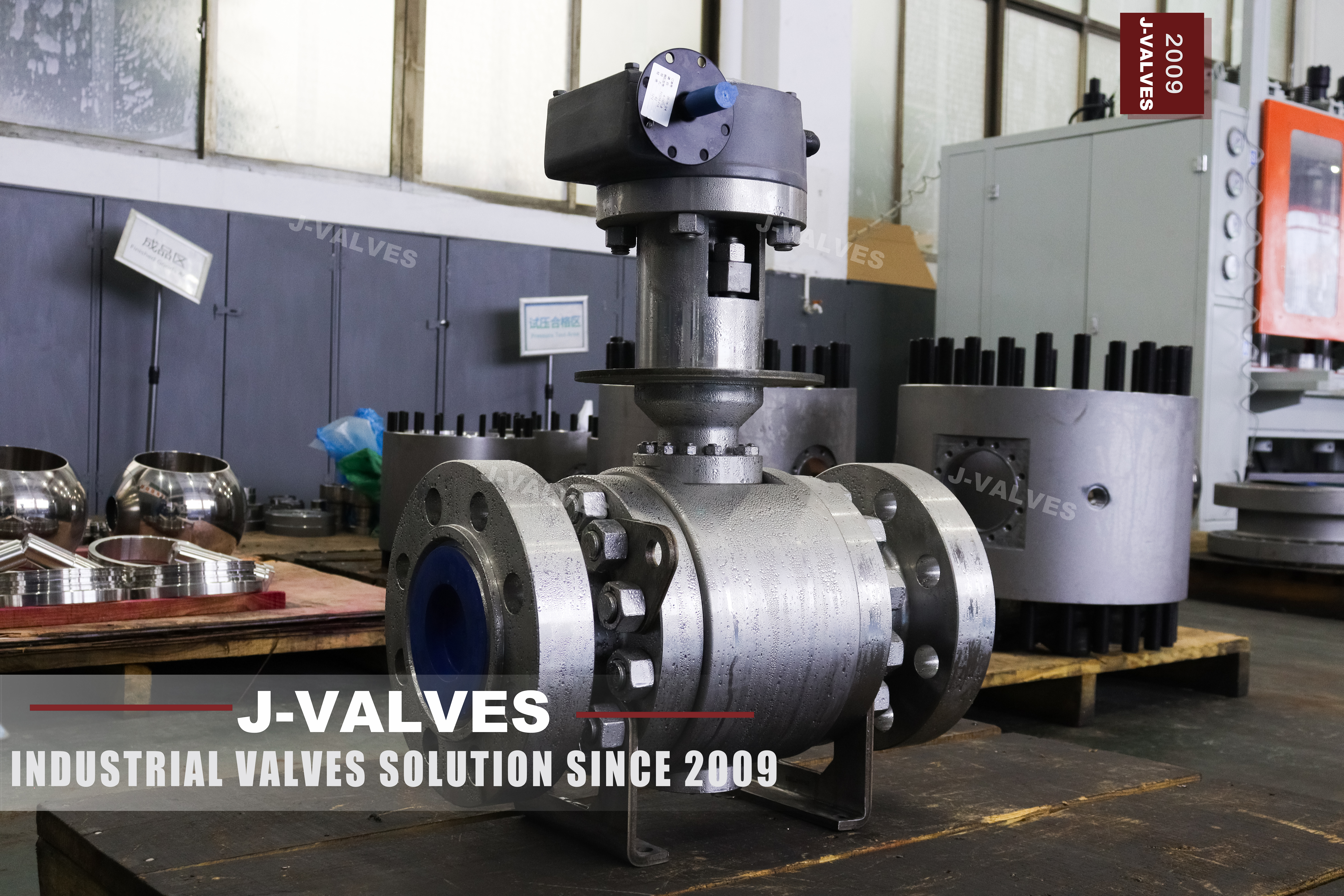
Welded body valves are sold on a sentence: no body flange, no bolted joint, therefore no leak path. The sentence is true about the joint it removes and false about the valve as a whole. A welded shell still has a stem going through the top of it, a drain plug going through the bottom, and, from six inch upward, two seat injection ports drilled through the side into each seat pocket. Each of those is a hole in the pressure boundary, and each has its own seal.
That distinction is not pedantry. A buyer who believes the valve has no openings will not put a maintenance interval on the packing, will not specify what happens to the drain plug, and will not ask how the cavity is relieved. Those three questions are the whole of the in service risk on a valve that cannot be opened.
This page is about the twelve inch Class 300 build with an electric actuator, but the argument applies to every welded valve on the site. It separates the shell from the openings, states what each opening is for, and follows the one that matters most: a cavity that cannot vent because the seats were ordered as double piston effect, on a body that has no joint to relieve it.
Design and Construction
The shell is a forged pipe section welded to two forged ends, full penetration, radiographed in full. There is no axial split anywhere on it: the ball and the seats go in before the second end is welded, and after that the only way into the cavity is through one of the openings listed in the next section. That is the design working as intended, and it is why the shell is quoted at fifty years.
The ball is on an upper and a lower trunnion, and at twelve inch those trunnions run in bearing blocks that are inserted into the body before the ends are welded on. That is the detail that makes a welded trunnion valve possible at this size: the bearing bores are machined in separate blocks that can be made and inspected on their own, rather than bored into a shell that cannot be reached.
The stem is a separate part, held in by a shoulder below the packing so that it cannot be blown out if the gland is removed with the line live. Two O-rings and a graphite gasket give the top assembly three barriers, and the sealant injection fitting lets grease be added to the stem seal without dismantling anything. None of that makes the stem opening disappear; it makes it maintainable.

Where the Body Is Still Open
Four openings pass through a welded body of this size, and each one is a seal with a different failure mode. Reading them together is the only way to see what the fifty year figure actually covers, because the figure is about the shell and three of these four are not the shell.
| Opening | What It Is For | What Seals It | Can It Be Renewed in Service |
|---|---|---|---|
| Stem | Turning the ball | Packing, gland, two O-rings | Yes, with the line live |
| Drain and vent | Emptying the cavity, proving DBB | Threaded plug with a sealant | Yes, but only with the cavity isolated |
| Seat injection, each seat | Emergency sealing of a weeping seat | Needle valve with a check | Yes, by injection, not by replacement |
| Trunnion access, where used | Fitting the bearing blocks before welding | Weld, or a plug | No |
The drain is the opening that deserves the most attention on a valve with double piston effect seats. A DPE seat is pushed onto the ball by pressure from both sides, which means the cavity between the two seats has no route out: when liquid is trapped there and warms up, it expands, and the pressure rises until something yields. The page's description says the seats tighten against the ball to prevent overpressure, which describes the problem rather than the solution, and the page's own seat table says the same thing in one word, no, in the row for cavity self relieving.
The two answers are the standard ones. Order single piston effect seats, and the cavity relieves itself into the line on the low pressure side; the price is that the upstream seat is not a barrier against the cavity, so a double block and bleed check reads differently. Or keep the double piston seats and fit an external relief, or write a procedure that opens the drain before the valve is warmed. What is not an answer is a drawing that says both double piston effect and self relieving, because the two cannot both be true of the same seat.
Technical Specifications
The table is the build as the page states it, with the openings written as openings. Nothing in it is a conversion, and the class is written both ways on the page, Class 300 and PN 50, which are the same row of the class table in API 6D.
| Item | Value |
|---|---|
| Size | 12 inch, DN 300 |
| Class | Class 300, PN 50 |
| Temperature | Minus 29 to plus 425 Celsius |
| Body | ASTM A105 forged carbon steel, welded shell |
| Openings | Stem, drain and vent, two seat injection ports |
| Ball | A105 with ENP or carbide coating, or solid F316 |
| Trunnion | Surface hardened A105 or 17-4PH, in bearing blocks |
| Stem | 17-4PH or nickel alloy 718 |
| Stem Seal | Two O-rings and graphite, anti blow out, injectable |
| Seat | Single or double piston effect, or a combination |
| Cavity Relief | Self relieving on SPE, external or by procedure on DPE |
| Ends | Butt weld to ASME B16.25, flanged transition on request |
| Actuation | Electric quarter turn, 15 to 120 seconds |
| Design and Test | API 6D and ASME B16.34, tested to API 6D and API 598 |
Two rows decide the service behaviour of this valve and neither of them is the body. The seat row decides whether the cavity can relieve itself, and the cavity relief row decides what has to be done when it cannot. A buyer who orders double piston effect because it sounds more secure has ordered a valve that needs a relief device, and the relief device is not on the page.
Standards and Compliance
API 6D covers the valve, and it is the document that expects a cavity relief means rather than a particular one. ASME B16.34 supplies the wall and the ratings behind the class. ASME B16.25 fixes the weld end profile. The seat arrangement, the injection fittings and the drain are design choices that the standard permits in more than one form, which is exactly why they have to be written on the order rather than read from the standard.
| Document | What It Fixes | What It Leaves to the Order |
|---|---|---|
| API 6D | Classes, test, marking, cavity relief intent | Which relief means, and per seat |
| ASME B16.34 | Wall, material groups, ratings | The seat and the openings |
| ASME B16.25 | Weld end profile | The field welding procedure |
| API 598 | Shell and seat test | The acceptance rate |
| API 607 and 6FA | Fire test of the design | Whether the unit shipped was tested |
| NACE MR0175 | Materials for sour service, on request | Whether the service is sour |
The fire test line is worth one sentence because it is often read the wrong way. A fire certificate is a type test on a design and a size: it says that a valve of this construction, with these seats, passed a defined test after the soft parts were destroyed. It says nothing about the unit in the crate, and nothing about the valve being fire proof. What survives is the metal contact between ball and seat once the polymer is gone.
Manufacturing Process
The ends, the pipe section and the bearing blocks are made separately. The blocks go into the shell first, because after the second end is welded there is no way to fit them. The ball and both seat assemblies are then loaded, the second end is aligned to the first, and the girth welds are made.
Alignment is the operation that decides the valve, and it is invisible afterwards. The two ends have to be coaxial to the bore and square to each other before welding, because a shell welded out of line cannot be straightened and the seats will show the error as uneven loading. The weld is full penetration and it is radiographed in full rather than by sample, which is the only record of the joint that will never be opened.
After welding the body is stress relieved if the procedure requires it, the bore and the seat pockets are finished, the drain and injection holes are drilled and tapped, and the stem assembly goes in from the top. The injection ports are drilled last on some builds so that the drill breaking into the seat pocket can be verified before the fitting is installed.

Quality Control and Testing
The shell test is applied at the multiple of the class that API 6D names, with the ball open so the cavity is pressurised with the body. There is no body joint to watch, so a weep at this stage is a weld or a plug, and the plugs are the ones that fail: a threaded drain plug that was not sealed correctly will weep at test pressure and be tight at line pressure, which is the worst kind of pass.
The seat test is run from each side and the leakage is collected and compared with the acceptance on the order. On a double piston build both seats hold in both directions, which is what makes a bleed check meaningful; on a single piston build the upstream seat does not hold against the cavity, and a test that expects it to is testing the wrong thing.
The cavity relief path is proved rather than assumed. On a self relieving build the upstream seat is checked for the relief direction at low pressure; on a double piston build the external relief, or the drain procedure, is written down and the drain is proved to open and reseat. That check takes minutes at the works and is almost never done at site.

Applications and Industry Service
Pipeline isolation is the first use, and the welded shell is chosen because the valve is often in a pit where a body joint would be a permanent weep. Twelve inch Class 300 is a common size for a section isolating valve on a distribution or a gathering line, and the electric actuator is chosen because there is power at the site and the valve has to be operated remotely.
The second use is anywhere a double block and bleed check is part of the operating procedure. That check only means something if the seats are barriers in both directions, which is the double piston case, and the same choice is what creates the cavity relief obligation. The two go together and should be ordered together.
The valve is the wrong choice where the medium can solidify in the cavity and cannot be drained, because the drain is a plug and not a flush connection. It is also the wrong choice where the cavity will be warmed by the sun or by tracing with the valve closed and no relief is fitted, because the pressure has to go somewhere and the seat is the softest part in the way.

Installation, Operation and Maintenance
The valve is welded into the line, and the field weld is made to the B16.25 profile at the valve end and to the pipe specification at the other. The body is supported so the pipe does not hang from the shell, and the drain and injection ports are left accessible: a drain that is buried in insulation or in a pit floor is a drain that will not be opened, and an injection port nobody can reach is a fitting that was bought for the drawing.
Operation is a quarter turn. The drain is used in two ways that should be written down: to prove the seats by bleeding the cavity with the valve closed, and to relieve the cavity before the valve is warmed on a double piston build. A drain used for the first purpose and not the second is how a cavity overpressure event is discovered by the seat rather than by the operator.
Maintenance is the packing, the injection ports and the drain. The packing is renewable with the line live and is the only dynamic seal on the valve. The injection ports are for an emergency, not a schedule: sealant buys time, and the page says as much when it warns that the seats have to be repaired at the first opportunity. The drain plug seal is a small part that is renewed whenever the plug is disturbed.
How to Specify and Order
The order lines below are the ones the page leaves open, and the first two are the ones that decide whether the cavity can look after itself.
| Line on the Order | What to Write | Why It Matters |
|---|---|---|
| Seat arrangement | Single or double piston effect, stated per seat | The two behave differently on cavity pressure |
| Cavity relief | Self relieving, external relief, or a written procedure | A DPE seat does not relieve itself |
| Drain | Size, thread and whether it is accessible after insulation | It is the only manual route out of the cavity |
| Injection ports | Fitted on both seats, with the fitting type | An emergency measure, not a maintenance item |
| Packing | Graphite, and the gland type | The only dynamic seal on the valve |
| Ends | Weld end profile and the pipe grade it joins | The field weld is made to both |
| Class and test | Class to API 6D with test pressure and duration | The class on the plate is a tested class |
| Actuation | Electric, with the stroke time at low voltage | The time at nominal voltage is the best case |
Read as a whole, the page describes a valve whose shell is genuinely closed and whose openings are genuinely not. The welds, the trunnion blocks and the butt ends are settled. What separates a valve that stays tight from one that vents its cavity through a seat is a seat arrangement that was chosen deliberately and a relief route that was written down before the valve was buried.
FAQ
Q: If the body is fully welded, where can it leak?
A: At the stem, at the drain plug and at the seat injection ports. Those three openings pass through the shell and each one is sealed by something that is not a weld. What the welded shell removes is the body joint, which is one leak path out of four, and it is the only one that the design eliminates completely.
Q: Why is a double piston seat a problem on a welded body?
A: Because the cavity between the two seats has no route out. A double piston seat is pushed onto the ball by pressure from both sides, so neither seat lets cavity pressure past. When liquid is trapped there and warms up it expands, and the pressure rises until a seat or a plug yields. On a bolted body the same condition exists, but the body can be opened; on a welded one it cannot.
Q: What are the seat injection ports for?
A: Injecting sealant into a seat that has started to weep, as an emergency measure that keeps a line running until the seat can be replaced. They are standard from six inch upward. Each port is a needle valve with a check, and the check is what keeps the cavity sealed when nothing is being injected.
Q: Does the drain plug count as cavity relief?
A: Only if somebody opens it. It is a manual route, and a manual route is a procedure rather than a device. On a single piston build the cavity relieves itself past the upstream seat and the plug is a convenience; on a double piston build the plug is the relief, and it only works if the procedure says when to open it and somebody follows it.
Q: Is a fire certificate a statement about this unit?
A: No. It is a type test on a design and a size, and it says the design restricted flow to a permitted rate after the soft parts were destroyed. It does not say the valve in the crate was tested, and it does not say the valve is fire proof. What survives a fire is the metal contact between ball and seat once the polymer is gone.


Hot Products


News
Urea Plant Ball Valves: The Wetted Path Survives Only While Oxygen Is Being Fed To It
Carbamate at 150 bar and 185 C eats stainless 50 times faster once the passive film starves. The valve cavity is where the oxygen runs out first.
Read More
Stiction: What A Ball Valve Becomes When Nobody Turns It
A valve that stood closed for years has not worn out. The seat has bonded to the ball, and the first stroke is a step, not a ramp. What the trace shows.
Read More
Molten Salt Ball Valves: The Valve Works at 565 C And Dies at 219 C
Salt freezes at 220 C and decomposes at 565 C. Everything a molten salt ball valve does happens in that 345 kelvin gap, and the gap is not generous.
Read More
Direct Air Capture Ball Valves The Vacuum Side Runs The Seal Backwards, And Three Hundred Thousand Strokes Decide The Design
A solid sorbent DAC plant moves 1.3 million cubic metres of air per tonne of CO2, then asks a DN50 ball valve to hold 0.9 bar from the wrong side.
Read More