

CHINA J-VALVES Offers Various High-quality I ndustrial Ball Valves
J-VALVES, a distinguished professional ball valve manufacturer rooted in China, takes pride in its extensive product portfolio. Our offerings span a wide range, including trunnion-mounted ball valves, floating ball valves, high-temperature ball valves, high-pressure ball valves, metal-sealed ball valves, ultra-low temperature ball valves, DBB ball valves, Three-way And Four-way Ball Valve, and fully welded ball valves. Each product is a testament to our commitment to precision engineering and reliable performance. Meticulously crafted, they are designed to not only meet but exceed the most stringent industrial demands, ensuring stable operation even under extreme conditions. This enables us to provide our clients with high-value services and makes our valves widely sought-after in industries.
Product Category
Contact Us


-
J-VALVES-Q41F
-
J-VALVES
Overview of the J-VALVES half inch Class 600 DBB ball valve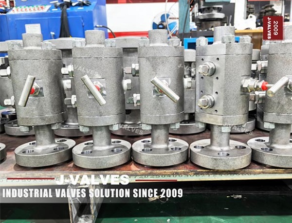
The photograph shows a small valve with two stems, two levers and one body. That is the first thing to understand about this article: it is not one ball with two seats, it is two balls in series inside a single forging, with a short space between them and a plugged tapping drilled into that space. Everything else on the page follows from that arrangement.
The build is half inch by half inch, Class 600, from minus 29 to plus 425 Celsius, in a normalised forged carbon steel body. Ends on the drawing can be threaded, socket welded, butt welded or flanged, and the photograph shows a flanged end on one side and a weld preparation on the other, which is worth noting because no single end list covers the combinations that are ordered.
The argument of this page is about counting. One line on a purchase order, two balls, two stems, two operating levers, and two different material stamps sitting on the same valve. An order that names the article and stops there has covered one of those five things.
Design and Construction
The body is a centre forging with an end piece bolted to each side, so the valve has two gasketed body joints and each of them is a pressure boundary. The two ball and seat assemblies sit in the centre piece, one behind the other, each with its own stem, its own packing and its own lever. Nothing about the two halves is shared except the body and the cavity between them.
That cavity is the working part. Close both balls, open the centre tapping, and whatever comes out has passed the upstream ball. That is the whole test, and it is the reason the construction exists in instrument and sampling duty, where the question is not whether a valve is shut but whether anyone can prove it is shut without breaking the line.
The two levers are a consequence of the two stems and they are not a detail. Each ball has to be operated separately, so the valve has two operating positions rather than one, and any procedure that assumes a single action is wrong for this article. Where the valve is used as an isolation point, both levers belong in the lockout, and the sequence of closing and of opening is written down rather than left to habit.
The ball travels with the medium in the ordinary way at this size, which is why the original page offers a trunnion version for high differential and high cycling duty. On a half inch valve at Class 600 the pressure load on a small ball is modest and a floating ball seals well, so the floating version is the standard build and the trunnion version is the exception bought for cycle life rather than for tightness.
The end connections are where the drawing does the work. A threaded end is a taper or a parallel thread and the two do not interchange, a socket weld end is a socket to ASME B16.11, and a butt weld end is a bevel to ASME B16.25. The photograph shows one flanged end and one weld preparation, which is a combination that appears on skids where the valve is welded into a run on one side and bolted to an instrument on the other.

Material Options
The body is a forging in A105, normalised. A105 is the grade and normalising is the heat treatment the specification requires; the letter N that appears after it on the casting is a record of that treatment and not a separate grade. That distinction has a practical consequence on this valve, because the body carries one stamp and the end piece carries another.
| Mark | What It Records | What It Does Not Record |
|---|---|---|
| A105N on the body | Grade A105, normalised, heat treatment recorded | Nothing about the end piece |
| A105 on the end piece | Grade A105, no treatment recorded on the part | Whether that piece was normalised |
| B7M studs | Hardness capped for sour service | Low temperature toughness |
| L7M studs | The low temperature variant | Sour service qualification |
| F6a stem | Martensitic stainless, hard chrome plated | Corrosion resistance of a 316 stem |
| RPTFE seat | Reinforced PTFE | Temperature above the polymer limit |
One grade with the treatment recorded on one part and not on the other is a documentation gap rather than two materials, and it is closed by a certificate that covers every pressure part rather than by reading the stamps. A 3.1 certificate naming one heat for the body and no heat for the end piece leaves the buyer unable to say what the end piece is.
The temperature floor on this valve is minus 29, and that is the figure for carbon steel in ordinary service. The original page claimed suitability down to minus 46 for the same body, which is not a property A105 has without impact testing and is in any case contradicted by its own parameter table. A carbon steel valve for minus 46 is a low temperature grade, and it is a different order.
The stem grade matters more than it looks on a small valve. F6a is hard and takes the chrome plate well, which is why it is the default for a small ball, and F304 or F316 is chosen where the medium is aggressive. The stem is a pressure boundary and a wear part at the same time, so the two requirements pull in different directions and the grade on the order is the compromise between them.
Technical Specifications
The word high pressure in the article name needs separating from the class number. Class 600 is the middle of the range in a process plant and it is a serious pressure on a half inch instrument line, where the tubing itself is often the limiting item. The class is the specified fact and high pressure is a description of the duty, and the two should not be read as one.
| Item | Value |
|---|---|
| Size | Half inch by half inch, DN 15 by DN 15 |
| Pressure class | Class 600, PN 100 in the API 6D table |
| Temperature | Minus 29 to plus 425 Celsius |
| Body | Normalised forged carbon steel, A105 |
| Ball | A105 with electroless nickel, or F304, or F316 |
| Stem | F6a, F304 or F316 |
| Seat | Reinforced PTFE, PEEK, or metal |
| Packing | PTFE V rings, or graphite above the polymer limit |
| Studs | B7M for sour service, L7M for low temperature |
| Ends | Threaded, socket weld, butt weld or flanged |
| Face to face | ASME B16.10 where tabulated for the end type |
| Bleed | Plugged tapping into the cavity between the balls |
| Operator | Lever, mini gearbox, or actuator |
| Design | API 6D, ASME B16.34, API 608 |
| Test | API 598 shell and seat |
The face to face line has a caveat that applies to the whole family. ASME B16.10 tabulates a length for a valve, and a two ball body is longer than the single valve the table describes, so the dimension on a double block and bleed article comes from the drawing. Quoting a tabulated length for this valve and then building to it is how a spool ends up short.
The class and the PN figure belong together and neither substitutes for the other. Class 600 is PN 100 by the table in API 6D, and PN is a bar designation. A page that prints a PN number calculated from a pressure in bar has done arithmetic where the standard offers a lookup, and the rounding is where the wrong figure gets onto a drawing.
Standards and Compliance
| Requirement | Document | What It Means Here |
|---|---|---|
| Product requirements | API 6D | Design, materials, marking |
| Product requirements | API 608 | Ball valves DN 15 to DN 600, Class 150 to 600 |
| Wall and rating | ASME B16.34 | Group 1.1 for A105, rating by class |
| Pressure test | API 598 | Shell at 1.5 times, seat at 1.1 times |
| Threaded ends | ASME B1.20.1 or ISO 7-1 | Taper threads, not interchangeable |
| Socket weld ends | ASME B16.11 | Socket dimensions and weld prep |
| Butt weld ends | ASME B16.25 | Bevel geometry |
| Material certificate | EN 10204 3.1 | Heat number for every pressure part |
This valve sits inside the scope of both product standards, which is not true of everything in the range. API 608 covers ball valves from DN 15 to DN 600 in Class 150 to Class 600, and a half inch Class 600 valve is comfortably inside it, so a buyer can ask for either or both and get an article that conforms.
The thread row is the one that causes the most returns on small valves. NPT and BSP are different thread forms, and BSP itself is two threads, a taper to ISO 7-1 and a parallel to ISO 228. They will start to engage and they will not seal, and by the time the leak appears the valve is on a skid. The order should name the thread form and the standard, not the country it is associated with.
Manufacturing Process
The body starts as a billet which is cut, heated and forged into a shape with two ball bores and two seat pockets in line. The two bores are the machining problem on this article: they have to be coaxial with each other and each has to be square to its own end face, and a small error in either shows up as a seat that leaks on one side only.
Normalising follows the forging. It refines the grain and relieves the forging stress, and it is the step the letter N on the body refers to. It is recorded per heat, which is why the certificate is the place to look for it rather than the stamp on the casting.
Machining is done with the end faces, the body joint faces and the seat pockets referenced to one centreline, and the seat pockets are checked against each other before the end pieces are fitted. On a valve this small the tolerances are tight in absolute terms because the parts are small, and the assembly is bench work rather than a fixture job.

Quality Control and Testing
The test that matters on a double block and bleed valve is the one the ordinary shell and seat test does not do. Shell and seat prove that each seat holds; they do not prove that the cavity can be bled and that nothing crosses into it from the upstream side. That is a separate operation, done with both balls closed and the centre tapping open, and it belongs on the test record.
| Step | Check | Acceptance |
|---|---|---|
| 1 Incoming | Heat number against the mill certificate | Chemistry and mechanicals |
| 2 Normalising | Heat treatment record for the body | By grade, recorded |
| 3 Identity | Positive material identification on body and end piece | Both parts, not one |
| 4 Shell test | Body and both joints at 1.5 times | API 598, no leakage |
| 5 Seat test | Each seat at 1.1 times, each direction | API 598 rate |
| 6 Cavity test | Both balls closed, centre tapping open | No flow into the cavity |
| 7 Torque | Operating torque recorded per stem | Baseline for later comparison |
| 8 Marking | Size, class, grade, standard | API 6D marking |
The identity row is where the two stamps resolve. Positive material identification on the body alone confirms the part that was already stamped and says nothing about the end piece. On a valve with two pressure parts from two heats, the check belongs on both, and the report should say which part each result belongs to.
Torque is worth recording on both stems even on a valve this small, because the two are separate mechanisms and they will not wear at the same rate. A valve that has been in service for a year and turns harder on one lever than the other is telling the operator which ball is carrying the duty, and that information only exists if a baseline was taken at commissioning.

Applications and Industry Service
The duty is instrument and sampling work: gauge and transmitter isolation, analyser houses, chemical injection skids, wellhead control panels and the small bore isolation points around a metering station. In all of them the reason for the article is proving, and a single valve that can be proved in place is worth two valves that cannot.
The second duty is double isolation where the space between the two barriers has to be vented before work starts. That is the same article used for a different reason: not to prove tightness but to guarantee that the pipe between the two balls is at zero before a fitter opens a joint. On a hydrogen or a sour gas sample line this is the difference between a procedure and a hope.
It is the wrong article where the line needs a single operating action. Two levers mean two things to operate and two things to get wrong, and on a remote or automated duty the two stems want two actuators or a linked drive. A double block and bleed valve specified as a drop in replacement for a single valve has been specified by shape rather than by function.
Installation, Operation and Maintenance
Install with the body supported and the end connections aligned before the threads or the welds are made up. On a threaded end the thread is the seal at the joint face and the body is not a lever, so the valve is held on the body flats and not on the lever. On a socket weld end the heat input is kept low and the valve is left open, because a closed ball with a hot socket can trap expansion against the seats.
Operate by closing both balls, then opening the centre tapping. What comes out is the proof. Close the tapping before opening either ball, because a cavity left open to atmosphere will draw in air and, on a dirty line, whatever the air carries with it.
For maintenance the line is isolated and vented, the end pieces are removed, and the two ball and seat assemblies come out from the centre. Seats are replaced as pairs, packing is renewed on both stems, and the studs are brought up in a cross pattern to the drawing figure. The cavity is cleaned and dried before assembly, and the valve is left with both balls open.
How to Specify and Order
The valve is fixed by six fields on the order: size, class, body grade, seat material, end connection and operator. On this article two of them need splitting. The end connection is a pair, one end and the other end, and they can differ. The operator is a pair as well, one per stem, unless a linked drive is specified.
Three things belong on the order beside the six lines: the cavity tapping and whether it is a plug or a valve, the thread form when the ends are threaded, and the certificate scope. The first decides whether the valve can be proved in place. The second decides whether it will seal. The third decides whether the buyer can say what the end piece is made of a year later.
Documents to name: the EN 10204 3.1 certificate with a heat number for the body and for each end piece, the normalising record for the body, the positive material identification report covering both, the shell, seat and cavity test record, and the general arrangement drawing with the face to face and both end details.
FAQ
Q: Is this a genuine double block and bleed valve?
A: Yes, and for a structural reason rather than a claim. The body carries two balls in series, so there are two independent isolating elements, and the tapping between them reaches the cavity that separates the two. A single ball with two seats is block and bleed unless both seats are double effect, which is a different article.
Q: Why does the body say A105N and the end piece say A105?
A: Because A105 is the grade and normalising is the heat treatment the specification requires; the letter N records that treatment on the part that carries it. It is one material with the treatment recorded in one place. The certificate has to name a heat for each pressure part, or the end piece has no material record.
Q: Does this valve work at minus 46?
A: Not as a carbon steel build. The floor for A105 in ordinary service is minus 29, which is what the parameter table on the original page states, and the claim of minus 46 elsewhere on that page contradicts it. A valve for minus 46 is a low temperature grade and a different order.
Q: Why are there two levers?
A: Because there are two stems, one per ball. The valve therefore has two operating positions rather than one, both levers belong in a lockout where the valve is an isolation point, and the closing and opening sequence is a procedure rather than a habit.
Q: What does 1/2 by 1/2 mean?
A: That the bore matches the nominal size at both ends, so the valve is full port. The notation exists because a reduced bore valve is written with two different numbers, and the pair is the fastest way to see which one is being quoted.


Hot Products


News
Why A Ball Valve Gets Harder To Turn: Five Causes, And The Test That Tells Them Apart
A ball valve that stiffens over months points at one of five parts. Measure torque with the line pressurised and again vented, and the split becomes visible.
Read More
The Ball Valve at Four Thousand Bar: Seat Load, Erosion And Fatigue in Waterjet Circuits
At 4,000 bar a 10 mm bore puts 31 kN on the seat and a 0.1 mm leak cuts steel. What a ball valve must survive in a waterjet or intensifier circuit.
Read More
Large Diameter Ball Valves: Four Limits That Change The Design
Above a certain size a ball valve stops being a scaled one. Ball weight, operator torque, body split and the test bench each set a limit at a different size.
Read More
Cast Or Forged Ball Valve Body, And What A Radiography Acceptance Level Actually Buys You
Casting or forging is only half the decision. What RT, UT, MT and a proof test each find in a ball valve body, and where the geometry defeats all of them.
Read More