

CHINA J-VALVES Offers Various High-quality I ndustrial Ball Valves
J-VALVES, a distinguished professional ball valve manufacturer rooted in China, takes pride in its extensive product portfolio. Our offerings span a wide range, including trunnion-mounted ball valves, floating ball valves, high-temperature ball valves, high-pressure ball valves, metal-sealed ball valves, ultra-low temperature ball valves, DBB ball valves, Three-way And Four-way Ball Valve, and fully welded ball valves. Each product is a testament to our commitment to precision engineering and reliable performance. Meticulously crafted, they are designed to not only meet but exceed the most stringent industrial demands, ensuring stable operation even under extreme conditions. This enables us to provide our clients with high-value services and makes our valves widely sought-after in industries.
Product Category
Contact Us


-
J-VALVES-Q41F
-
J-VALVES
Overview of the J-VALVES three port F316 DBB ball valve, 0.75 x 0.5 x 0.5 inch Class 1500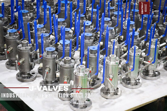
This is a three port valve, not a two port valve with an extra tapping. It has one three quarter inch connection and two half inch connections, and the whole reason for buying it is that one body can isolate, block twice and bleed without a manifold of three separate valves bolted to a bracket.
Double block and bleed is a function, not a shape, and the shape is where most of the confusion starts. The function is that two seats close against the flow and a port between them opens to atmosphere, so the space between the two seats can be proved empty before anything downstream is opened. On a three port valve the question that decides whether the function works is which of the three connections the two seats sit between, and that question is answered by a drawing rather than by a catalogue description.
The valve is forged A182 F316, Class 1500, with a three quarter inch inlet and two half inch ports, and the seat inserts are reinforced PTFE or PEEK depending on the temperature. It is a small valve with a large amount of function packed into it, and it is normally found on an instrument root, a sample point, an injection skid or a gauge connection.
Design and Construction
A three port ball valve is a ball with two seats and a port pattern cut through the ball itself. The pattern decides the function: an L port connects one port to one other at a time, and a T port connects one port to two others at once or two ports to each other. Neither is better, and a valve ordered without the pattern stated is a valve that will be wrong about half the time.
The two half inch ports on this valve are the pair that face the seats, and the three quarter inch port is the one that turns the corner. Read that way, the isolation duty is between the two half inch ports and the three quarter inch port is the line connection, which is the arrangement used where a small bore instrument line has to be isolated from a larger process connection.
The bleed is a separate small connection into the cavity, and it is the part that makes the valve a DBB valve rather than a valve with two seats. It is normally a plug or a small needle valve, and it has to be rated for the same class as the body, because when it is opened it sees full line pressure on the cavity side as soon as either seat passes.
The construction described on the source page is a floating ball, and that has a consequence worth stating plainly. A floating ball seals on the seat it is pushed into, so a two port floating valve only ever has one barrier. On a three port body the ball can be captured between two coaxial seats, and only in that geometry do both seats load at once. Whether this valve is built that way is a question for the drawing, and it is the first question to ask before the DBB claim is accepted.

Material Options
F316 is the forged austenitic grade with molybdenum in it, and it is chosen on small bore high pressure work for the molybdenum rather than for the nickel. The molybdenum is what gives the grade its resistance to pitting and crevice attack in chloride bearing media, and on an instrument root in a coastal or offshore plant that is the failure mode that matters.
| Component | Standard Build | Options | What It Decides |
|---|---|---|---|
| Body | A182 F316 forged | F316L for welded connections, F51 for higher strength | Corrosion resistance and weldability |
| Ball | Solid F316 | F316 with nickel plating or hard chrome | Whether the seat survives dirty media |
| Seat insert | Reinforced PTFE | PEEK for higher temperature, or a metal seat | The temperature ceiling of the valve |
| Stem | F316 | 17-4PH for higher torque | Stem life at pressure |
| Packing | PTFE chevrons | Flexible graphite for temperature | Stem seal and fire performance |
| Body joint | Not applicable on a one piece forging | Two piece body where offered | Whether the ball can be changed in line |
| Bolting | A193 B8M with A194 8M | B7 with 2H where the body is carbon steel | Thermal match and corrosion |
| Bleed | Plug or needle valve | Needle with a bonnet | Whether the cavity can be vented controllably |
The seat insert is the part that sets the temperature limit of the whole valve, and on a small DBB valve it is also the part that sets the pressure limit in practice. A reinforced PTFE insert at this class will hold, but it deforms under load at temperature and takes a set, and a valve that has taken a set will not seal again at ambient until it has been cycled.
PEEK is the upgrade and it is bought for two different reasons that are often confused. The first is temperature, because it keeps its shape higher up the range than PTFE does. The second is wear, because a small valve on an injection skid cycles far more often than its size suggests, and the seat sees the cycle count rather than the pressure.
Technical Specifications
Class 1500 in group 2.2 of ASME B16.34 is 3600 psi at 38 C, and API 6D clause 7.2 records the same class as PN 250. Both figures are worth having on the page because the two conventions are used by different buyers and a quotation that names only one of them will be questioned by the other.
| Item | Value |
|---|---|
| Connections | 0.75 inch inlet, two 0.5 inch ports, DN 20 x DN 15 x DN 15 |
| Pressure class | Class 1500, recorded as PN 250 in API 6D clause 7.2 |
| Rating | 3600 psi at 38 C in group 2.2 |
| Body | A182 F316 forged, one piece with a bleed tapping |
| Ball | Solid F316, port pattern to the drawing |
| Seat | Reinforced PTFE or PEEK, spring loaded |
| Bleed | Plug or needle valve into the cavity, rated to the class |
| Ends | NPT to ASME B1.20.1, socket weld to B16.11, butt weld to B16.25 |
| Face to face | ASME B16.10 where tabulated, otherwise the signed drawing |
| Temperature | Minus 29 to plus 425 C as a body figure, insert limited |
| Operator | Lever with a locking device as standard |
| Test | API 598 shell and seat, each port proved with the cavity vented |
The page this came from records the class as PN 260, and that number cannot be found in either convention. API 6D clause 7.2 lists seven designations and the one for Class 1500 is PN 250, which is also the designation in EN 1092-1. PN 260 looks like a conversion of the rating into bar with the decimal dropped, and it has been replaced with PN 250 here rather than repeated.
Standards and Compliance
Two product standards exist for ball valves and only one of them covers this valve. API 608 runs from DN 15 to DN 600 in Class 150 to Class 600, and a Class 1500 valve is outside it by class. API 6D covers the higher classes and is the standard that applies here, which means the marking, the documentation and the test all come from 6D rather than from 608.
| Requirement | Document | What It Means Here |
|---|---|---|
| Wall and rating | ASME B16.34 group 2.2 | 3600 psi at 38 C |
| Product requirements | API 6D, Class 1500 | Design, marking, documentation |
| Threaded ends | ASME B1.20.1 | NPT taper and engagement |
| Socket weld ends | ASME B16.11 | Socket depth and gap |
| Butt weld ends | ASME B16.25 | Bevel and bore match |
| Pressure test | API 598 | Shell 1.5 times, seat 1.1 times |
| Fire test | API 607 or ISO 10497 | Type test, scope to be read |
| Material certificate | EN 10204 3.1 | Heat number matched to the part |
The source page also cites an annex of API 6D as the basis of the DBB claim, and that citation should be treated as a claim rather than as a proof. What can be checked on the valve is simpler: there are two seats, there is a bleed into the cavity between them, and the test record shows each seat proved with the cavity open. A DBB valve that has never been tested that way is a valve with two seats and an assumption.
The fire test note needs the same reading. API 607 and ISO 10497 are the same test in two documents, and a certificate covers the sizes and classes that were tested rather than the whole catalogue. On a three port valve the certificate also has to say which port arrangement was tested, because a fire test on a two port body does not carry across to a three port one.
Manufacturing Process
The body is machined from a forging rather than cast, which at this size is the only sensible route: three connections meeting inside one small body means the internal passages are drilled and the seats are machined from the outside, and a casting of this shape would have cores thin enough to shift.
The ball is machined with its port pattern cut through it and then ground on the sphere, and the pattern is the part that has to be checked against the drawing rather than against a sample. An L port and a T port look identical from the outside of the ball until the valve is assembled and someone turns it.
The seats are machined with the insert pocket and the spring pocket on the same face, so the spring loads the insert evenly. On a small valve the spring is a light wave washer or a small coil set, and its job is only to hold the insert against the ball when there is no pressure, because above a few bar the pressure does the work.

Quality Control and Testing
The heat number is etched on the forging and repeated on the certificate, and on a small stainless valve the identity check is also a check that the body and the ball are the same grade. A F316 body with a F304 ball is not a defect that shows up in a pressure test, and it is the kind of substitution that shows up two years later as pitting on the ball.
| Step | Check | Acceptance |
|---|---|---|
| 1 Incoming | Heat number against the mill certificate | A182 F316 chemistry |
| 2 Identity | Positive material identification on body and ball | Grade match, molybdenum present |
| 3 Threads | Gauge check on every threaded connection | ASME B1.20.1 ring and plug gauges |
| 4 Pattern | Port pattern against the drawing | L or T confirmed, orientation marked |
| 5 Shell test | Body and all connections at 1.5 times | API 598, no leakage |
| 6 Seat test | Each seat at 1.1 times, cavity vented | API 598, no visible leakage on a soft seat |
| 7 Bleed | Bleed opened under pressure on each seat | Flow proves the cavity is isolated |
| 8 Final | Ports capped, lever tied, marked, packed | Works standard |
Step seven is the one that separates a DBB valve from a valve with a bleed. With the valve closed and one side pressurised, opening the bleed should produce nothing after the first release of trapped volume. If it keeps running, one seat is passing and the valve is not blocking twice, whatever the drawing says.

Applications and Industry Service
Three port DBB valves live on the small bore side of a plant, where a process connection has to be isolated and proved before an instrument is removed. Gauge roots, transmitter impulse lines, sample points, analyser take offs and chemical injection points are the same problem in different clothes: a small connection at full line pressure that someone has to open by hand.
The reason a three port body is bought instead of two valves is space and leak points. Two isolators in series plus a bleed is three bodies, six connections and three chances to leak, and on a skid that has been designed to the last millimetre it is also three times the footprint. One body with three connections does the same job with one item to inspect.
It is the wrong valve where the flow has to pass through at full rate, because a three port body at this size has a reduced bore and the pressure drop across it is not negligible. It is also the wrong valve where the medium would solidify in the cavity, because the cavity is a dead space by design and a dead space full of product is a dead space that blocks.

Installation, Operation and Maintenance
Threaded connections on a small valve are the joint that fails, not the seat. Tape or compound goes on the male thread only, the first two threads are left bare so that nothing enters the bore, and the valve is held on the body flats rather than on the lever when it is tightened. A valve tightened by its handle has a bent stem before it has been in service.
The bleed should be oriented so that it vents to a safe place rather than onto the person opening it. On a line carrying a hazardous medium the bleed is normally piped away, and the piping is part of the installation rather than an accessory, because a bleed that discharges at face height will not be used.
Maintenance is limited to the packing gland and the seat inserts, and on a one piece forged body the seats come out through the port connections rather than through a body joint. The gland nut is tightened a fraction at a time with the line depressurised, and a stem that has been over tightened will feel stiff for the rest of its life and will wear the packing unevenly.
How to Specify and Order
Six lines fix this valve and the first one is not the size. It is the port pattern, because L and T are different valves with the same description, and a valve ordered without it will be supplied to whatever the works happens to build. The other five are the three connection sizes and types, the class, the body grade, the seat insert and the operator.
Four questions belong to the installation rather than to the valve: which connection is the process side, which two are the isolated side, where the bleed discharges, and whether the line will be opened while it is live. Those four answers decide the port pattern, the bleed arrangement and whether a locking device is required on the lever.
Documents to name in the order: the EN 10204 3.1 certificate with the heat number matched to the body, the thread gauge record if the connections are threaded, the seat test record showing each seat proved with the cavity vented, the bleed rating, and the drawing that carries the port pattern and the face to face dimension.
FAQ
Q: What does the three part size mean?
A: It means one three quarter inch connection and two half inch connections, not three equal ports. The three quarter inch port is the process connection and the two half inch ports are the isolated side, which is the arrangement used where a small bore instrument line has to be isolated and proved before it is opened.
Q: How is the double block and bleed function proved?
A: With the valve closed and one side pressurised, the bleed is opened. It should release the trapped volume and then stop. If it keeps running, one seat is passing and the valve is blocking once rather than twice, whatever the description says. That test belongs on the record as well as on the bench.
Q: Is this valve a trunnion or a floating design?
A: The source page describes a floating ball and then pastes a trunnion seat module underneath it. Those are different constructions. On a three port body a floating ball can be captured between two coaxial seats and both can load, but whether that is how this body is made is a drawing question, and it is the first one to ask.
Q: Why is the class PN 250 and not PN 260?
A: Because API 6D clause 7.2 lists seven designations and the one for Class 1500 is PN 250, which is also the EN 1092-1 designation. PN 260 appears on the source page and cannot be found in either convention; it looks like a conversion into bar with the decimal dropped.
Q: What limits the temperature, the body or the seat?
A: The seat. The F316 body figure runs to 425 C, and a reinforced PTFE insert sits well below that. Above the insert limit the answer is PEEK in the same body, which is why the insert is the line that matters on the order.


Hot Products


News
Why A Ball Valve Gets Harder To Turn: Five Causes, And The Test That Tells Them Apart
A ball valve that stiffens over months points at one of five parts. Measure torque with the line pressurised and again vented, and the split becomes visible.
Read More
The Ball Valve at Four Thousand Bar: Seat Load, Erosion And Fatigue in Waterjet Circuits
At 4,000 bar a 10 mm bore puts 31 kN on the seat and a 0.1 mm leak cuts steel. What a ball valve must survive in a waterjet or intensifier circuit.
Read More
Large Diameter Ball Valves: Four Limits That Change The Design
Above a certain size a ball valve stops being a scaled one. Ball weight, operator torque, body split and the test bench each set a limit at a different size.
Read More
Cast Or Forged Ball Valve Body, And What A Radiography Acceptance Level Actually Buys You
Casting or forging is only half the decision. What RT, UT, MT and a proof test each find in a ball valve body, and where the geometry defeats all of them.
Read More