


CHINA J-VALVES Offers Various High-quality I ndustrial Ball Valves
J-VALVES, a distinguished professional ball valve manufacturer rooted in China, takes pride in its extensive product portfolio. Our offerings span a wide range, including trunnion-mounted ball valves, floating ball valves, high-temperature ball valves, high-pressure ball valves, metal-sealed ball valves, ultra-low temperature ball valves, DBB ball valves, Three-way And Four-way Ball Valve, and fully welded ball valves. Each product is a testament to our commitment to precision engineering and reliable performance. Meticulously crafted, they are designed to not only meet but exceed the most stringent industrial demands, ensuring stable operation even under extreme conditions. This enables us to provide our clients with high-value services and makes our valves widely sought-after in industries.
Product Category
Contact Us


-
J-VALVES-Q41F
-
J-VALVES
Overview of the J-VALVES DN25 PN100 A105 Two-Piece Floating Ball Valve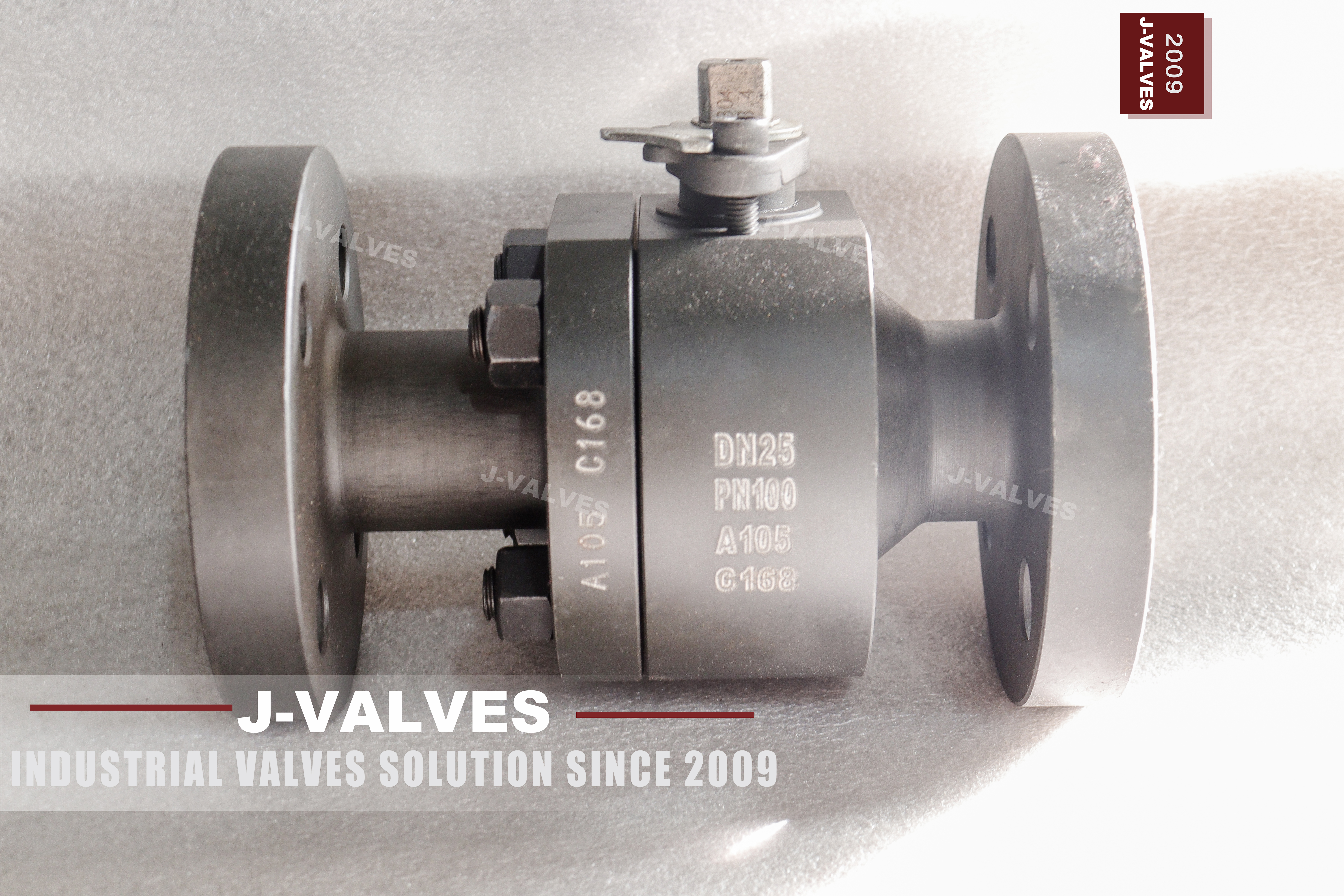
The J-VALVES DN25 PN100 two-piece floating ball valve is a forged carbon steel isolation valve for metric pipework near the top of the ordinary pressure range. The bore is 25 mm and full port, both ends are EN 1092-1 PN100 flanges with a B2 raised face, and the body is forged from ASTM A105 in two pieces: a main body and one bolted end cap. The ball is not carried on trunnions. It sits between two seat rings, and line pressure pushes it onto the downstream seat.
What settles the structure at one inch is load, not fashion. The force the ball hands to the seat is line pressure acting over the bore area, so floating is still comfortable at PN100 in a 25 mm bore, while the same class on a large bore has to move to trunnions. Two pieces rather than three: a second joint buys nothing here, because ball and both seats come out through one end cap, and two joints would mean two more gaskets on a valve carried by hand.
Most of these valves go where the pressure is high and the flow is modest: dosing skids, analyser and sampling lines, instrument air, hydraulic power packs and OEM packages drawn to European flanges. The buyer in those lines is not comparing classes. They are closing a 25 mm gap in pipework already flanged to EN 1092-1 and want the highest ordinary class that will still bolt to the flange welded on.
Design and Construction
The body is one forging split once. The main body carries the ball, both seat pockets, the stem bore and one flange; the end cap carries the second seat and closes the bore, held by studs through a gasketed face. Both seats hold, so the valve seals in either direction, but only one end is detachable, and the arrow on the body shows which. Fit it the way the arrow points, not the way the pipe run makes convenient.
Because the ball floats, nothing in the cavity behaves like a piston. Liquid trapped between the seats and warmed by the line pushes the ball off the upstream seat and vents back into the pipe, so there is no relief device to add, no seat ring with a piston face and no sealant injection fitting, because there is no piston effect seat to inject behind. On a small high pressure valve that is the quiet advantage: fewer paths out of the pressure boundary.
The stem is inserted from inside the body and held by a shoulder, so stripping the gland does not release it against pressure. Packing is PTFE V-rings as standard and flexible graphite where temperature demands it; the gland can be tightened with the valve in service, which is a load adjustment and not a parts replacement. A spring loaded plunger bridges ball, stem and body, and that path is measured before the valve is packed.
Fire safety here is geometry before it is a certificate. Behind each soft seat is a metal shoulder, so when the seat ring burns away the ball lands on metal and the passage closes metal to metal. The body joint gasket is flexible graphite or a graphite filled spiral wound ring, because a PTFE sheet has nothing left to seal with after a fire.
Material Options
The table is the material build for this size and class. Two rows matter more than the rest at PN100: the seat and the body joint gasket.
| Component | Standard Material | Optional Upgrade | Service Notes |
|---|---|---|---|
| Body and end cap | ASTM A105 forged | A182 F304 or F316, A350 LF2 | Group 1.1, 425 C body ceiling |
| Ball | A351 CF8 or CF8M, ENP plated | Stellite overlay | One solid piece, machined and lapped |
| Stem | A276 410 or 420 | A276 304 or 316 | Blow-out proof, separate from the ball |
| Seat rings | RPTFE | PTFE, PEEK, PPL, metal | The seat sets the valve temperature |
| Stem packing | PTFE V-rings | Flexible graphite | Gland adjustable in service |
| Body joint gasket | Flexible graphite | Spiral wound, 316 with graphite | No PTFE sheet at this joint |
| Body bolting | A193 B7 with A194 2H | B7M with 2HM | B7M for sour service |
| Anti-static device | Spring loaded stainless plunger | One per body | 10 ohm or less, measured |
| Operator | Lever | Worm gear, pneumatic, electric | ISO 5211 pad on request |
The seat limits the sale, not the body: RPTFE covers the ordinary range, PEEK sits near 260 C, PPL near 280 C, and only a metal seat with graphite reaches 425 C.
A105 is the grade most European data sheets ask for by its EN counterpart, P250GH to EN 10222-2. The two are close enough in chemistry and strength that specifications treat them as interchangeable, but they are not the same document, and the difference shows in the certificate: a European buyer will expect EN 10204 3.1 against the grade on the drawing, and an ASTM certificate does not automatically satisfy it. Say which basis the project wants and the mill certificate follows.
Stainless bodies, A182 F304 or F316 forged, are for the media A105 cannot take: demineralised water, mild chemical dilution, and lines where a carbon steel body would discolour the product. What stainless does not buy is a higher rating; both grades are read from their own group in ASME B16.34, and the reason to change is the medium, not the class.
Technical Specifications
Read the plate and the table as two different things. The plate carries 10.0 MPa, which is the nominal figure the PN100 designation stands for. What the valve may hold at a given temperature comes from a table: the tabulated value for Group 1.1 at 38 C in ASME B16.34 is 102.1 bar, and it falls from there as temperature rises. Close to 100, not the same number, and only the table governs at temperature.
| Item | Value |
|---|---|
| Nominal size | DN25, NPS 1 |
| Pressure class | PN100, Class 600 in the ASME system |
| Nominal pressure | 10.0 MPa on the plate, a reference figure |
| Body material | ASTM A105 |
| Body style | Two-piece, main body plus one bolted end cap |
| End connection | EN 1092-1 PN100, Type 11 flange |
| Flange facing | Form B2 raised face |
| Flange outside diameter | 140 mm |
| Bolt circle | 100 mm |
| Bolts | 4 |
| Raised face diameter | 68 mm |
| Flange thickness | 24 mm |
| Bore | Full port, 25 mm |
| Face to face | EN 558, confirmed on the signed GA drawing |
| Design | API 608, wall thickness to ASME B16.34 |
| Pressure test | API 598, shell 1.5 times, seat 1.1 times |
| Fire test | API 607 and ISO 10497 |
| Temperature | Minus 29 to plus 425 C, limited by the seat |
| Operator | Lever as standard |
Face to face follows EN 558 and is confirmed on the signed general arrangement drawing, because the lever, any gearbox and the flange thickness all change what fits between two flanges. The bore is full port at 25 mm, which is the nominal size and not automatically the pipe bore: a DN25 pipe in a common wall has a slightly larger inside diameter, and a swab is sized to the valve bore because the valve is the narrowest point in the run.
Standards and Compliance
PN100 is the one place in the PN series where both systems have a number, which is why it gets misread. EN 1092-1 has a PN100 step, so a PN100 valve can be bolted to a PN100 flange. API 6D clause 7.2 records Class 600 as PN 100, so the same designation is correct on an ASME rated valve. The flanges are still not the same part. At DN25 the EN flange is 140 mm across on a 100 mm bolt circle with a 68 mm raised face; the Class 600 part at NPS 1 is 124 mm on 88.9 mm with a 50.8 mm raised face. Both have four holes, and neither takes the other's studs: one is drilled metric and the other inch.
The facing carries a second trap. EN 1092-1 raised faces come in two finishes, and B1 is only specified up to PN40; at PN100 the form is B2, with the finer turned or serrated finish. A quotation that says raised face without naming the form may have been priced from a PN16 drawing. The option written on the original page as a Type E ring joint face is a category error too: in EN 1092-1, Type E is a spigot, which pairs with a Type F recess, while a ring joint groove is an ASME B16.5 facing.
The product standard is API 608, written for floating and trunnion ball valves with flanged, threaded or welded ends, and it is what requires the anti-static path, the blow-out proof stem and the test regime this valve is built to. It is not API 6D. Here 6D appears once, to justify the PN100 designation, never as a design basis: 6D is the pipeline document, built around trunnion designs, cavity testing and double block and bleed, none of which a 25 mm floating valve provides.
| Requirement | Standard | What J-VALVES Supplies |
|---|---|---|
| Body wall thickness | ASME B16.34 Class 600 | Not less than the standard class |
| Product standard | API 608 | Floating ball, anti-static path, blow-out proof stem |
| Pressure test | API 598 | Shell 1.5 times, seat 1.1 times, every valve |
| Fire test | API 607, ISO 10497 | Certificate supplied with the batch |
| Flange dimensions | EN 1092-1 PN100 | Type 11 flange, Form B2 facing |
| Face to face | EN 558 | Series stated on the GA drawing |
| Marking | EN 19, API 608 | Size, class, material, heat number, flow arrow |
| Material documents | EN 10204 | 3.1 certificate for body, ball and stem |
| Fugitive emission | ISO 15848-1 | On request, with the test report |
Manufacturing Process
The body begins as a forging rather than a casting, and at this size that is practical more than premium: a 25 mm body has thin walls in absolute terms, and a shrinkage cavity that would be a footnote in a large casting would be a serious fraction of the wall here. Each forging is normalised, hardness checked and traced by heat number. The two halves are match marked, and the joint faces are machined with the pair bolted together, so the faces end up flat against each other rather than each flat on its own.
The ball is machined and lapped as one solid piece and then plated; the seats are turned, and the seat pockets are checked for depth, because a pocket a few hundredths shallow loads the ring unevenly and the leak only appears after a thermal cycle. Assembly is dry, the gland is set to the written procedure, and the lever stops are set to a quarter turn before test.

Quality Control and Testing
Ten checks stand between the forging and the crate, and the order matters, because the first four cannot be corrected later: chemistry and certificate, forging soundness on the pressure boundary, the machined geometry of flanges and joint faces, and the ball. The middle three are assembly: seat fit, gland load, lever travel. The last three are the tests and the marks.
| Step | What Is Checked | Standard or Acceptance |
|---|---|---|
| Incoming material | Heat number, chemistry, mechanical properties | EN 10204 3.1 against A105 |
| Forging soundness | Laps, seams and internal defects on the boundary | Visual and ultrasonic |
| Machining | Flange facing, bolt circle, joint face flatness | EN 1092-1 and the drawing |
| Ball | Roundness, surface finish, plating | Drawing, before assembly |
| Seat fit | Pocket depth, gasket groove, ring contact | Drawing |
| Assembly | Gland load, lever travel, stops | Written procedure |
| Shell test | 1.5 times the rating, both directions | API 598, no leakage |
| Seat test | 1.1 times, each seat separately | API 598, rate A |
| Anti-static | Resistance, ball to stem to body | 10 ohm or less |
| Marking and packing | Plate data against the record | EN 19, API 608 |
Every valve is tested rather than sampled. The shell test runs at 1.5 times the rating and the seat test at 1.1 times, each seat separately, and both results are recorded against the serial number that goes on the plate. The anti-static reading is recorded too, because API 608 requires the path and a reading is the only proof of it. Documentation follows the order: 3.1 certificates, test record, and the general arrangement drawing as signed.

Applications and Industry Service
The natural home is small bore, high pressure duty: dosing and injection skids, analyser and sampling systems, instrument air and nitrogen headers, hydraulic power packs, seal flush and cooling circuits, and OEM packages drawn to EN flanges. In those lines the valve is turned a few times a shift, the medium is clean, and what matters is a flange that matches, a seat that does not weep after a year under pressure, and a lever a technician can reach.
It is worth being clear about where this valve is wrong. Dirty or scaling media wear a soft seat and pack the cavity, and a strainer upstream is cheaper than a rebuild. Sour service needs B7M bolting and a stem inside the NACE MR0175 hardness limit, stated at order. Dry chlorine and oxygen are their own category. And a line that will be pigged, or a bore of several inches at this class, belongs on a trunnion valve.
Installation, Operation and Maintenance
Fit the valve with the arrow downstream, the lever where an operator can reach it, and enough clearance that the lever does not foul the adjacent flange through its quarter turn. Use the gasket made for the B2 raised face: a full face sheet cut to the outside diameter sits on the unraised rim, and on a PN100 joint that is where it will weep. Bring the studs up in a cross pattern in at least three passes, and support the pipe rather than the valve.
Maintenance is one joint. Isolate, vent and drain, take the studs out, and the end cap, one seat and the ball come away; the joint gasket is replaced rather than reused, and the faces checked for marking before the cap goes back. Nothing on a floating valve can be replaced under pressure. The gland can be tightened in service, but the body joint is a pressure boundary, and the line has to be down before it opens.
How to Specify and Order
Six answers settle an order: size and class, flange standard and facing form, bore, seat material against the actual temperature rather than the line design temperature, operator and mounting interface, and the test and documentation package. Two have to be fixed before the body is machined: the facing form, B2 unless the drawing says otherwise, and the flange standard. If the pipe is ASME this valve will not bolt up at any price, and the order is the Class 600 version, not a PN100 valve with an adapter ring.
A one inch PN100 enquiry is rarely a single valve. It arrives with a line list, and the flanges, facing forms and seat materials are better decided together than one valve at a time.
FAQ
Q: Will a PN100 valve bolt to a Class 600 flange?
A: No, and this is the one PN number where both sides look valid. EN 1092-1 has a PN100 step, so a PN100 valve can bolt to a PN100 flange, and API 6D clause 7.2 records Class 600 as PN 100, so the nameplate is correct either way. The flanges are still different parts. At DN25 the EN flange is 140 mm outside diameter on a 100 mm bolt circle with a 68 mm raised face; the ASME Class 600 flange at NPS 1 is 124 mm on 88.9 mm with a 50.8 mm raised face. Both are four hole patterns, and neither accepts the other studs, because one is drilled for metric and the other for inch threads.
Q: Is PN100 the same as 100 bar?
A: PN is a designation, not a working pressure. The plate on this valve carries 10.0 MPa, the nominal figure the PN100 classification stands for, but what the valve may hold at a given temperature is read from a table. For Group 1.1 carbon steel at 38 C, ASME B16.34 gives 102.1 bar at Class 600, and the figure falls as temperature rises toward the 425 C ceiling of that group. EN 1092-1 carries its own curve for the material group behind a PN100 flange. Two tables, one valve, and only the table governs at temperature.
Q: Should the raised face be B1 or B2, and is a ring joint an option?
A: At PN100 it is B2. EN 1092-1 raised faces come in two finishes, and B1 is only specified up to PN40; from PN63 upward the form is B2, with the finer turned or serrated finish that takes a spiral wound gasket properly. A quotation that says raised face without naming the form may have been priced from a PN16 drawing. A ring joint is a different matter: that is an ASME B16.5 facing, and in EN 1092-1 the letter E denotes a spigot that pairs with a Type F recess, not a ring groove. If the line is ring joint throughout, the flange standard has to change with it.
Q: Can this valve be repaired with the line still in service?
A: Only the gland. The end cap carries one seat and closes the bore, and the joint between it and the main body is a pressure boundary, so it has to be isolated, vented and drained before the studs come out. On a floating valve the ball is held only by the two seats, so there is nothing to work on under pressure beyond tightening the packing, which is a load adjustment. The valve can stay in the pipe while the end cap comes off; the pipe cannot stay under pressure.


Hot Products


News
Ball Valves in A Kraft Pulp Mill: Black Liquor, Green Liquor And The Cost of Choosing The Alloy by Habit
White liquor at pH 14 cracks carbon steel welds, black liquor sets solid below 100 C, green liquor dregs grind seats: alloy choice and torque in a kraft mill.
Read More
Slug Flow And Ball Valves: What Actually Arrives At The Seat
A slug is liquid mass with momentum, not a pressure spike. What changes at the seat, in the cavity and at the actuator when liquid reaches a ball valve.
Read More
Ball Valves in Direct Lithium Extraction: PH 1 Eluate, Gypsum Scale And 438,000 Cycles in Twenty-Five Years
Direct lithium extraction swings valves from pH 1 eluate to pH 12 caustic, 48 column switches a day and gypsum scale. Materials, seats and torque.
Read More
Ball Valves in Geothermal Brine: Silica Scale, Chloride Cracking And The Cooling Trap
Why geothermal brine destroys ball valves: retrograde silica scale, calcite at the flash point, chloride cracking above 60 C and the 250 C seat limit.
Read More