

CHINA J-VALVES Offers Various High-quality I ndustrial Ball Valves
J-VALVES, a distinguished professional ball valve manufacturer rooted in China, takes pride in its extensive product portfolio. Our offerings span a wide range, including trunnion-mounted ball valves, floating ball valves, high-temperature ball valves, high-pressure ball valves, metal-sealed ball valves, ultra-low temperature ball valves, DBB ball valves, Three-way And Four-way Ball Valve, and fully welded ball valves. Each product is a testament to our commitment to precision engineering and reliable performance. Meticulously crafted, they are designed to not only meet but exceed the most stringent industrial demands, ensuring stable operation even under extreme conditions. This enables us to provide our clients with high-value services and makes our valves widely sought-after in industries.
Product Category
Contact Us


-
J-VALVES-Q47F
-
J-VALVES
Overview of the J-VALVES 6 inch Class 900 F316 actuated trunnion ball valve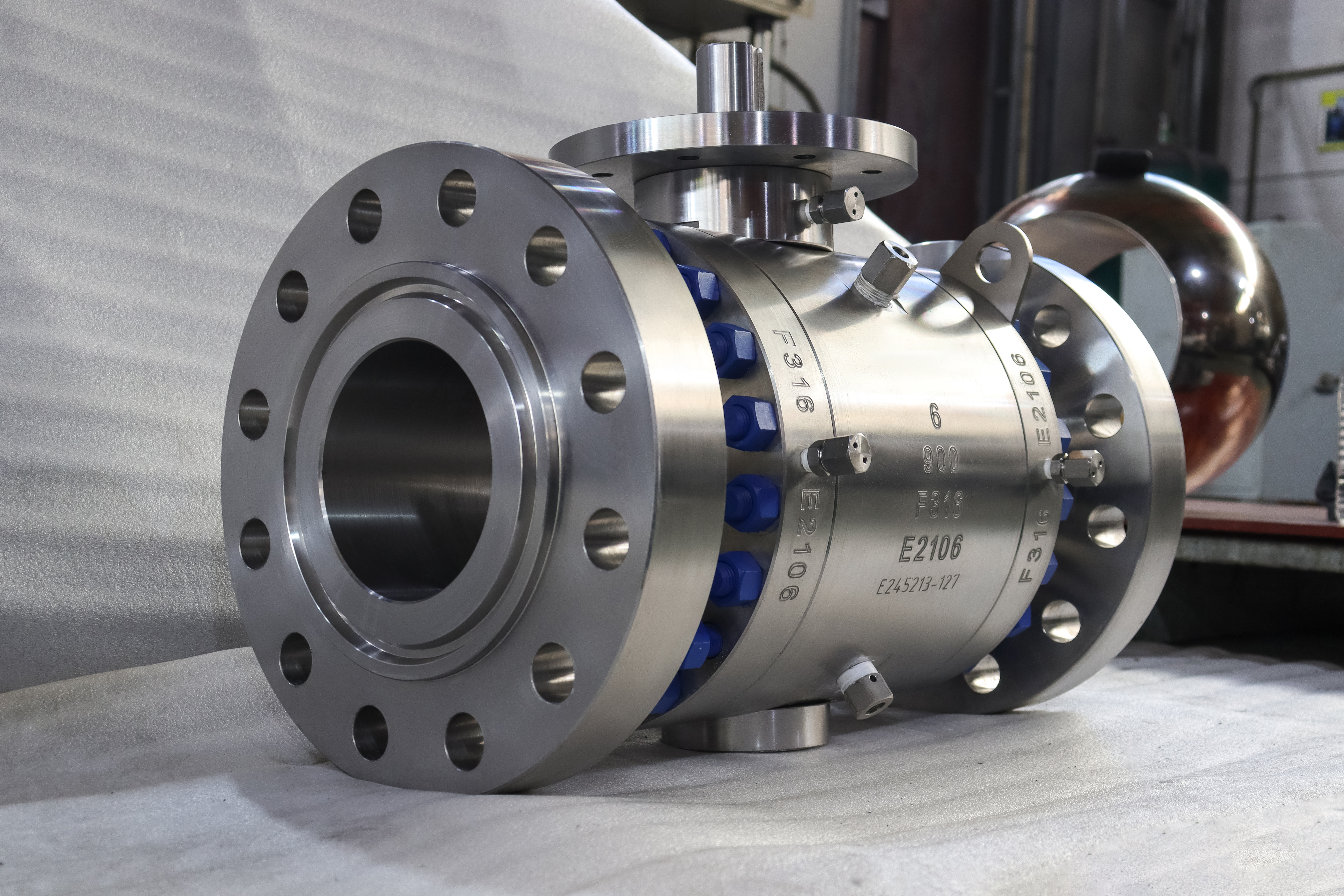
This is a six inch Class 900 trunnion mounted ball valve in forged ASTM A182 F316, photographed before any operator has been fitted. The keyed stem stands bare above a drilled top pad, the two end caps are closed by their own rings of blue studs, and the flanges are ASME B16.5 Class 900 with a machined facing. The centre section carries the size, the class, the grade and the heat number as raised characters, which is the only place on the valve where all four are stated together.
That bare stem is the point of the page. A quarter turn valve at this size is bought as a body and finished as a machine: lever, worm gear, pneumatic cylinder, electric quarter turn actuator or gas over oil unit all bolt to the same pad, and none of them can be chosen properly until the pad size, the stem square and the torque are known. Projects that leave the operator until commissioning are the ones that end up welding an adaptor on site.
In practice a six inch ball at Class 900 is past the size where a lever is comfortable for a person to break away against line pressure, so the pad is normally drilled for a gearbox and the lever is the exception. That is a statement about the size, not about this particular valve: the same body takes either, and the photograph shows the interface both of them share.
The service it fits is a high pressure stainless line where the valve has to be operated from a control room or from a walkway rather than by hand at the valve: emergency shutdown loops, remote isolation on manifolds, and process lines in chemical plants where the medium decides the grade and the class decides the wall.
Design and Construction
Three parts make the body: the centre, and one cap on each side, each cap pulled down by a full ring of studs onto a spiral wound gasket. Both trunnion bearing blocks live in the centre section, which never comes apart, so the stem axis and the lower trunnion axis keep their relationship every time a cap is removed. On a two piece body the lower bearing sits in the removable cap, and that is the structural reason a three piece body is preferred where the trim will be inspected more than once.
The ball is carried top and bottom and does not travel with pressure. Seat load comes from a spring pack behind each seat plus the pressure term, and because the ball does not move, the torque curve is flat across the quarter turn. A flat torque curve is what makes an actuator choice predictable: the cylinder or the gear sees close to the same resistance at breakaway, mid travel and seating, so sizing it on one measurement is defensible in a way it never is on a floating ball.
Three openings cross the pressure boundary and each one is a place where the valve can leak: the joint under each end cap, the stem bore with its packing, and the cavity plug at the bottom of the centre section. The plug is not an accessory. It is the opening that lets the cavity be vented during a double block and bleed check, and on a valve that will be actuated it is also the point where an operator standing at the valve is no longer needed, because the check is done at the vent rather than at the handle.

Material Options
F316 is the austenitic grade with two to three percent molybdenum, and the molybdenum is there for chloride: pitting, crevice attack and chloride stress corrosion cracking all move back relative to a 304 body. That is a corrosion argument and not a pressure argument, which matters because the two are constantly confused. A stainless body at Class 900 is rated slightly below a carbon steel body of the same class at ambient temperature, so nobody buys 316 to get a stronger valve.
The L grades lower the carbon and exist for welded construction; on a flanged valve that is never welded they buy nothing, and in the ASME B16.34 tables they sit in a different group with a lower rating, so ordering F316L for a flanged valve is a small step backwards unless a weld is planned. F321 and F347 stabilise the carbon for service that would otherwise sensitise the grain boundaries, which is a high temperature argument again, and neither of them changes the class.
| Component | Standard Material | Optional Upgrade | Service Notes |
|---|---|---|---|
| Body and end caps | ASTM A182 F316 forging | F316L for welded fabrication; F321 or F347 for sensitisation resistance | Forged to shape; ultrasonic examination to ASTM A388 only when ordered |
| Ball | F316 with electroless nickel plating | Hard chrome; tungsten carbide; cobalt based hard facing | Coating is a wear surface on a corrosion resistant base |
| Trunnion | F316 surface hardened | 17-4PH precipitation hardening stainless | Both bearings in the centre section, not in the caps |
| Stem | 17-4PH stainless | F316 with electroless nickel; nickel based alloy for sour service | Keyed, blowout proof, hardness limited on NACE orders |
| Top pad | Integral, drilled and tapped | Pad size and stem square stated on the order | The interface the actuator is bought against |
| Seat | PEEK for the high temperature end | Reinforced PTFE; metal seat with flexible graphite | The seat, not the body, sets the valve temperature |
| Body joint gasket | Flexible graphite spiral wound | Metal ring joint gasket | One per joint, two per valve |
| Bolting | A193 B8M studs with A194 8M nuts | B7 studs with 2H nuts | B7 on a stainless body is the corrosion weak point |
Technical Specifications
The table below fixes what a standard fixes. Size, class, grade, flange standard and facing, the test regime and the documents are all checkable against a catalogue and against the certificate that arrives with the valve, and none of them depend on a drawing that has not been issued yet.
It does not fix the dimensions that belong to a drawing. Wall thickness is a calculation from ASME B16.34 and lives on the design record. Face to face is tabulated in ASME B16.10 by size and class and is confirmed on the drawing that ships with the order. Printing either figure without a drawing behind it means publishing something no one has signed off.
| Item | Value |
|---|---|
| Size | 6 inch, DN150 |
| Pressure class | Class 900, recorded as PN 150 in API 6D clause 7.2 |
| Body style | Three piece forged body, trunnion mounted ball |
| Body material | ASTM A182 F316, ASME B16.34 group 2.2 |
| Rating | Group 2.2 at Class 900 reads 2160 psi at 38 C; carbon steel in group 1.1 reads 2220 psi at the same temperature |
| Flange | ASME B16.5 Class 900, raised face or ring joint |
| End options | Butt weld ends to ASME B16.25 |
| Face to face | ASME B16.10 for NPS 6 Class 900, confirmed on the signed general arrangement drawing |
| Temperature, body | Group 2.2 service range down to minus 254 C; the flange end rating stops at 1000 F, which is 538 C |
| Temperature, valve | Set by the seat: about 260 C for PEEK, 200 C for PTFE, metal seat for higher |
| Stem | Keyed, bare, on a drilled top pad as photographed; operator supplied to order |
| Top pad | Four tapped holes, pad size and stem square to be confirmed on the order |
| Seat design | Single piston effect as standard; double piston effect or double isolation on request |
| Product standard | API 6D; API 608 does not reach Class 900 |
Standards and Compliance
API 6D is the product standard for this valve, and one line explains why: API 608 covers flange sizes DN 15 to DN 600 at classes 150 to 600, so a Class 900 valve sits outside it on class alone, before any question of seat type is raised. The documents that travel with a 6D valve are the 6D set, covering marking, material traceability, pressure test records and the cavity and drain provisions.
The operator is a separate purchase and a separate set of rules, and this is where valve pages usually stop short. The valve standard fixes the valve; the pad on top of it is dimensioned to ISO 5211, the standard that defines pad size, bolt circle and stem square for quarter turn actuators, and the actuator itself carries its own standard and its own certificate. A buyer who specifies the valve and leaves the pad to chance is buying two components that will meet for the first time in a warehouse.
The rating itself is a table lookup in group 2.2 of ASME B16.34: 2160 psi at 38 C against 2220 psi for carbon steel in group 1.1. Stainless is therefore marginally lower at the cold end, and the gap closes and then reverses as the temperature climbs, which is the reason a stainless body is chosen for hot chloride service rather than for pressure.
| Requirement | Standard | What J-VALVES Supplies |
|---|---|---|
| Wall thickness and rating | ASME B16.34 group 2.2 | Design calculation; 2160 psi at 38 C |
| Pipeline valve requirements | API 6D | Marking, documentation, cavity and drain provisions |
| Product standard | API 6D | API 608 stops at Class 600 and does not reach this valve |
| Pressure testing | API 598 | Shell at 1.5 times, seat at 1.1 times the rating |
| Fire test | API 607, or ISO 10497 as the equivalent | Type test with a size and class scope printed on the certificate |
| Flange facing | ASME B16.5 | Raised face or ring joint groove, cut to the series ordered |
| Actuator pad | ISO 5211 | Pad size and stem square confirmed on the order |
| Material certificate | EN 10204 3.1 | Body and trim, heat number matched to the marking |
Manufacturing Process
The body starts as a forging rather than a casting, so there is no pattern and no sand: a billet is upset, punched and then machined to shape. That is why the surface in the photographs is machined all over and why the raised characters stand out so cleanly. The buyer gets a dense grain structure and no shrinkage porosity; the supplier gets a long machining cycle and pays for it in the price.
The stem bore and the top pad are cut in the same set-up as the body bore, because the stem axis has to be square to the flange faces. If it is not, the actuator pulls the stem sideways on every stroke and the packing pays for it. This is one of the few quality points on a valve that is decided by a single machining operation and is invisible once the valve is assembled and painted.
Assembly follows the machining. Seats and springs go into the centre section, the ball goes between them, the caps are landed and the studs are brought up in stages in a cross pattern, then the valve is cycled on a stand and the torque is recorded. That recorded figure is what the actuator is sized against later, which is why the test bay and the actuator supplier have to be talking about the same valve.

Quality Control and Testing
The first check is identity, and on an austenitic valve it is not a formality. The heat number raised on the body is matched to the mill certificate, and where the order asks for it a positive material identification reading confirms that the body and the trim are the grades the certificate claims, because 304 and 316 look identical on a bench and a mixed part is a corrosion failure waiting for the right medium.
| Step | What Is Checked | Standard or Acceptance |
|---|---|---|
| 1 Material | Heat number against the mill certificate; chemistry and tensile | ASTM A182 F316, EN 10204 3.1 |
| 2 Identity | Positive material identification on body and trim when ordered | Grade match, no mixed parts |
| 3 Dimensional | Flange facing, bolt circle, face to face | ASME B16.5 and B16.10, or the signed drawing |
| 4 Machining | Seat pocket concentricity, joint face flatness, stem square to the flange faces | Drawing tolerance |
| 5 Shell test | Body and both body joints at 1.5 times the rating | API 598, no leakage |
| 6 Seat test | Each seat at 1.1 times the rating, cavity vented | API 598; zero visible leakage on soft seats |
| 7 Function | Quarter turn operation with the torque recorded | Record issued with the test report |
| 8 Final | Cavity drained, bore dried, faces masked, paint, caps | Works standard |
The shell test is where a three piece body separates itself from a two piece one in practice, because there are two joints to hold instead of one and both are under full pressure at the same time. A joint that weeps here is a machining or a torque fault rather than a gasket fault, and chasing it on site wastes a shutdown that the test bay could have saved.
The functional step is the one that matters for an actuated valve and the one most data sheets omit. Cycling the valve on the stand gives a torque figure for that valve, not for the model, and an actuator sized on a catalogue average will be either oversized and slow or undersized and stalled. The figure belongs on the test record and it belongs in the enquiry, and if it is missing the actuator is being chosen by guesswork.

Applications and Industry Service
The ordinary homes for this valve are oil and gas gathering and processing lines where the pressure needs 900 class and the medium is wet enough to need molybdenum, and chemical and petrochemical plants handling chlorides, brines and mildly acidic streams. It also appears in seawater systems on coastal and offshore plants, where the alternative to a corrosion resistant body is a shorter service life and a repaint that never works.
Where the valve is actuated, the reason is usually distance or hazard rather than convenience: an emergency shutdown loop that has to close in seconds, a manifold valve behind a barrier, or a line at temperature that nobody should stand next to. In each case the valve is the easy part and the interface is what fails, which is why the pad and the stem engagement deserve the same attention as the body grade.
It is not the right valve for every high pressure duty. Past the flange end rating the body has to change material group, and where the medium eats 316 the answer is a higher alloy, not a heavier wall. Where the line runs cold the austenitic body is comfortable but the seat and the gasket are not necessarily, and both carry their own limits.
Installation, Operation and Maintenance
Fit the actuator with the valve in the position it will occupy, not on a bench, because a quarter turn unit that is aligned on a bench is often misaligned on a vertical stem. The stem key engages the actuator bore, the pad bolts pull the two faces together, and the coupling has to take the drive without taking side load. A shimmed or over-tightened coupling shows up later as stem wear and a weeping gland, and neither is covered by any warranty that a buyer wants to argue about.
In service the valve is operated a quarter turn and the position indicator on the gear or the actuator tells the operator where it is. Because the stem is retained by the body rather than by the gland, the packing can be tightened with the valve live, and the upper stem seal can be renewed once the cavity has been vented. No body joint on this design may be broken under pressure: each one is wetted by full line pressure all the way round.
For a three piece body the maintenance advantage is real but narrower than the catalogue suggests. Both caps come away with the pipe still bolted up, which lets the ball and seats out without cutting a spool or lifting the valve. What has to happen first is isolation and venting, and what has to be accepted afterwards is that two joints were opened and must be re-gasketed and re-torqued.
How to Specify and Order
Six decisions fix the valve: size and class, body grade with its certificate, flange facing and whether a ring ships with it, seat type with or without a bleed requirement, the operator, and the face to face standard. Four of those are usually missing from the first enquiry, and on an actuated valve the most often missing is the operator.
Three numbers go with the operator and they are not interchangeable: the pad size, the stem square and the torque. The first two come from the pad drawing and the third from the test record of the valve that will actually be shipped. An enquiry that names the pad and the stem square and asks for the torque can be answered with an actuator that fits; an enquiry that names only the size gets an actuator that nearly fits.
Documents should be named on the order. That means EN 10204 3.1 for body and trim, the hydro test record, the dimensional report, the fire test certificate with its size and class scope, and the torque record if an actuator is part of the scope. Every one of them is available, none arrives unless it is written down, and the purchase order is the only place that gets recorded.
FAQ
Q: Can this valve be supplied with an actuator fitted?
A: Yes. The pad in the photograph is where a quarter turn actuator lands, and the valve is supplied bare, with a worm gear, with a pneumatic cylinder or with an electric actuator. What has to be decided before the order is the pad size, the stem square and the torque the valve needs, and that torque is measured on the valve that ships rather than taken from a catalogue average.
Q: Why is the stem bare in the photograph?
A: Because the operator is a separate purchase. The valve is built and tested with the pad machined and the stem keyed, and the gear or the actuator goes on afterwards. Photographing it bare is honest about what is being chosen: the body is the valve, and the operator is an interface bolted to it.
Q: Does API 608 apply to this valve?
A: No. API 608 covers flange sizes DN 15 to DN 600 at classes 150 to 600, so a Class 900 valve sits outside it on class alone, before any question of seat type. The valve is built and documented to API 6D.
Q: What torque should the actuator be sized for?
A: The torque of the valve that is actually shipped, which is measured on the stand before dispatch and issued with the test record. A figure taken from a catalogue for the model is an average, and an actuator sized on an average is either slow or marginal at the end of the travel.
Q: Is stainless stronger than carbon steel at Class 900?
A: Slightly weaker at ambient. Group 2.2 at Class 900 reads 2160 psi at 38 C against 2220 psi for carbon steel in group 1.1. The stainless body is bought for the medium, not for the rating, and the gap closes and reverses as the temperature climbs.


Hot Products


News
Stainless Steel Ball Valve Grades: 304, 316 And 316L, And What Actually Decides
Molybdenum is the difference that decides the duty, carbon is the difference that gets missed, and the chloride in the line matters more than the price.
Read More
Ball Valve Spare Parts for Overseas Projects: The Wear Part List, The Quantity Math, And Four Traps
Why isolation valves fail on calendar time, not cycles. Wear part lists, Poisson stock maths, seat kit traps and the clauses that decide year six.
Read More
Ball Valves On A Bottom Loading Gantry: Creep, Dry Break And The Test That Proves Neither
A loading gantry cycles a ball valve far more than it is designed for and still cannot prove shut-off. Where creep starts, and what to specify.
Read More
Lined Ball Valves in Acid Service: The Liner Does Not Fail, The Steel Behind It Does
The valve came out of the line looking better than most valves that come out of a hydrochloric acid line. Three inch, PFA lined, cast body, Class 150, fourteen months in service on a 32 percent acid transfer duty at 55 to 60 degrees C, about forty open and close cycles a week. The paint was intact.
Read More