

CHINA J-VALVES Offers Various High-quality I ndustrial Ball Valves
J-VALVES, a distinguished professional ball valve manufacturer rooted in China, takes pride in its extensive product portfolio. Our offerings span a wide range, including trunnion-mounted ball valves, floating ball valves, high-temperature ball valves, high-pressure ball valves, metal-sealed ball valves, ultra-low temperature ball valves, DBB ball valves, Three-way And Four-way Ball Valve, and fully welded ball valves. Each product is a testament to our commitment to precision engineering and reliable performance. Meticulously crafted, they are designed to not only meet but exceed the most stringent industrial demands, ensuring stable operation even under extreme conditions. This enables us to provide our clients with high-value services and makes our valves widely sought-after in industries.
Product Category
Contact Us


-
J-VALVES-Q47F
-
J-VALVES
Overview of the J-VALVES 30x30 inch Class 900 A105 large bore trunnion ball valve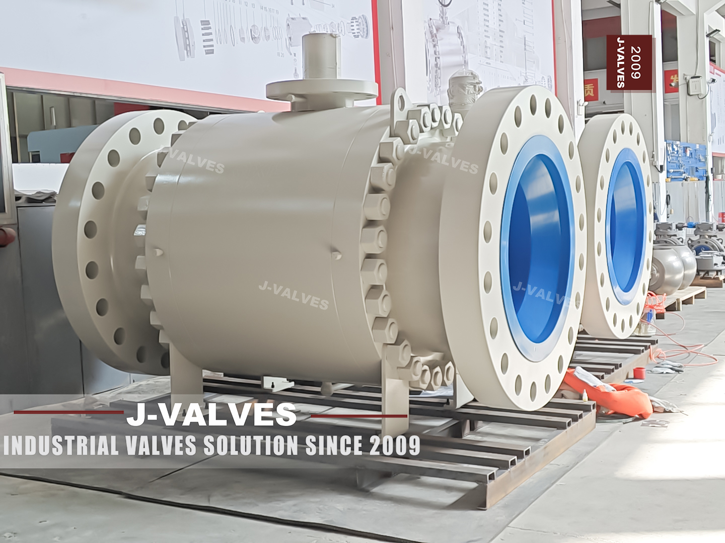
Thirty inches at both ends and thirty inches through the ball: this is a full bore valve, and the doubled size in the name is there to say so. It sits at the top of the size range for a three piece forged body, at Class 900, in A105 carbon steel, with ring joint flanges and a worm gear as the standard operator. It is the valve a transmission line uses when the line itself is the plant and the block valve has to isolate a whole section of it.
At this size the flange standard is the first thing that has to be corrected rather than the last. ASME B16.5 covers flanges from NPS half inch to NPS 24, and a 30 inch valve is outside it. The flanges on this body are drilled to ASME B16.47, in series A or series B, and the two series do not share a bolt circle. A purchase order that says B16.5 at 30 inch is an order that cannot be built, and a valve delivered to the wrong series cannot be bolted to the line.
Everything else follows from the size. The body is a large forging with two large caps, the ball is carried on trunnions in separate bearing blocks, the cavity holds a lot of liquid, and the valve is installed with a crane and then supported so that the pipe does not carry it. None of that is special pleading; it is the ordinary difference between a 30 inch valve and a 6 inch one.
Design and Construction
The body is three pieces with both trunnion bearings in the centre section, which at 30 inch is the arrangement that keeps the stem and the lower bearing coaxial. The caps carry the ring joint flanges and their own stud rings, and each cap is a forging in its own right rather than a plate. That is what makes a large three piece body different from a large two piece one: there are two joints to machine and two joints to hold, but the internals come out without cutting the line.
The ball is full bore and large, and the seat load comes from a spring pack plus the pressure term rather than from the ball being pushed downstream. The trunnions take the side load, which at this size is the load that would otherwise have to be carried by the seat and the stem. The bearings run in metal backed self-lubricating bushes, and the reason a 30 inch valve can be turned by a gearbox at all is that those bearings are doing their job.
The cavity is the part nobody thinks about until it matters. A 30 inch body holds a substantial volume between the seats, and on a liquid service that volume expands when it warms. A single piston effect seat relieves that expansion into the line on the low pressure side; a double piston effect seat does not, and then the design has to provide a relief route. The seat arrangement is therefore a safety decision on this valve rather than a preference.
The ring joint is the only facing offered, and that is correct at this class and size. A raised face joint relies on gasket compression over a wide area, and at 30 inch Class 900 the bolt load needed to keep that compression is not something a flange of this size is designed to deliver. The ring joint puts the seal on a metal ring in a groove, and the ring is a separate item bought to ASME B16.20.

Material Options
A105 is the default and for a gas transmission valve it is usually right: it is a carbon forging with good strength, it is weldable, and the whole pipeline around it is carbon steel. The options are the low temperature grade A350 LF2 and the austenitic grades F316 and F316L, and the choice between them is about the medium and the design temperature rather than about the class, because the class is fixed at 900 whatever the body is made of.
The one thing to add on a forging this size is examination. A 30 inch body and two 30 inch caps are heavy forgings, and heavy forgings are where internal discontinuities live. Ultrasonic examination to ASTM A388 is a supplementary requirement rather than a default, which means it has to be written on the order if it is wanted, and on a valve of this size it usually should be.
| Component | Standard Material | Optional Upgrade | Service Notes |
|---|---|---|---|
| Body and end caps | ASTM A105 forging | A350 LF2 for low temperature; A182 F316 or F316L for corrosion | Ultrasonic examination to A388 on request |
| Ball | A105 with electroless nickel plating | Hard chrome; tungsten carbide coating; cobalt based hard facing; solid F316 | Full bore, 30 inch passage |
| Trunnion | A105 surface hardened | 17-4PH precipitation hardening stainless | Bearings in separate blocks at this size |
| Stem | 17-4PH stainless | Nickel based alloy for high strength or sour service | Blowout proof, keyed for the gear |
| Seat | PEEK | Metal with flexible graphite; hard faced metal seat | The seat sets the working temperature |
| Ring joint gasket | Soft iron ring | Low carbon steel; F316 plated ring | Bought to ASME B16.20, not supplied with the valve |
| Bolting | A193 B7 with A194 2H nuts | B8M with 8M nuts for the stainless build | Torque values come from the joint calculation |
| Operator | Worm gear | Hydro-pneumatic for line break or ESD; electric; hydraulic | Gear is standard at this size, not an option |
Technical Specifications
The table below carries the two corrections that matter at this size, and both of them are about standards rather than about numbers. The flange is B16.47 rather than B16.5, and the length is a drawing dimension confirmed against the project rather than a table value taken for granted.
| Item | Value |
|---|---|
| Size | 30x30 inch, DN750, full bore |
| Pressure class | Class 900, recorded as PN 150 in API 6D clause 7.2 |
| Body style | Three piece forged body, side entry, trunnion mounted ball |
| Body material | ASTM A105 forging, ASME B16.34 group 1.1 |
| Flange | ASME B16.47 series A or B, ring joint facing; ASME B16.5 stops at NPS 24 |
| End options | Butt weld ends to ASME B16.25 |
| Face to face | Confirmed on the signed GA drawing against the project piping class |
| Bore | Full bore, 30 inch through the ball |
| Seat | PEEK as standard; metal with flexible graphite on request |
| Seat arrangement | Single piston effect standard; double piston effect or combined DIB on request |
| Temperature | Minus 29 to plus 425 C as published; the seat sets the working limit |
| Stem | 17-4PH, blowout proof, keyed for the gear |
| Operator | Worm gear standard; hydro-pneumatic, electric or hydraulic on request |
| Design standard | ASME B16.34 and API 6D |
| Test standard | API 598, shell at 1.5 times and seat at 1.1 times the rating |
| Painting | Sky blue RAL 5015 as standard |
Wall thickness is not in that table and never will be. At NPS 30 and Class 900 the wall is a calculation from ASME B16.34 against the material group and the design temperature, and the result belongs to the design record that the buyer can ask for. A catalogue page that printed a wall thickness for this size would be printing a number that had not been calculated for the valve in the crate.
Standards and Compliance
The flange question is settled by scope. ASME B16.5 is written for NPS half inch to NPS 24, so a 30 inch flange is outside it by size alone, before any question of facing or class. ASME B16.47 covers the larger sizes in two series, A and B, which differ in bolt circle and in flange outside diameter, and a valve drilled to the wrong series will not mate with the line. The series belongs on the order and on the drawing.
API 6D governs the valve as a pipeline product: marking, documentation, the cavity and drain provisions, and the test regime. It is the standard that applies here, and API 608 does not, because 608 stops at Class 600. A Class 900 valve at 30 inch is the clearest case in the catalogue of a valve that cannot be described under 608 at all, and a data sheet that lists both is listing a standard that has nothing to do with the product.
Testing follows API 598 with the shell at 1.5 times and the seat at 1.1 times the rating. On a body this large the shell test is a slow, wet operation with a lot of water in the cavity, and the drain and dry steps afterwards take as long as the test. Fire testing is a type test to API 607 with a size and class scope, and the scope on the certificate is the part to read.
| Requirement | Standard | What J-VALVES Supplies |
|---|---|---|
| Flange dimensions | ASME B16.47 series A or B | Series named on the order and on the drawing |
| Wall thickness and rating | ASME B16.34 group 1.1 | Design calculation and rating from the group table |
| Pipeline valve requirements | API 6D | Marking, documentation, cavity and drain provisions |
| Pressure testing | API 598 | Shell at 1.5 times, seat at 1.1 times the rating |
| Fire test | API 607 | Type test certificate with its size and class scope |
| Ring joint gasket | ASME B16.20 | Groove cut to the ring series ordered; ring bought separately |
| Forging examination | ASTM A388, supplementary | Ultrasonic report when the order asks for it |
| Material certificate | EN 10204 3.1 | Body and trim, heat number matched to the marking |
Manufacturing Process
A 30 inch body starts as a large forging and is machined on a boring mill rather than a lathe, because the part is too big to spin and too heavy to handle twice. The bore, the seat pockets and the joint faces are cut from the same datum, and at this size that datum is a setup that takes hours to establish and cannot be casually repeated. The quality of the valve is largely decided in that setup.
The caps are machined as a matched pair with the centre section, and the ring joint grooves are cut last, after the joint face is flat, because a groove cut into a face that is still moving will be out of profile. That is the point at which a large valve either seals at the flange or gives the site a leak it cannot fix without a regrind.
Assembly is a crane job. Seats and springs go in, the ball is lowered between them, the caps are landed and the studs are brought up in stages in a cross pattern with the valve supported so that its own weight does not load one side of the joint. Then the valve is tested, drained, dried for long enough that the cavity is actually dry, masked, painted and crated with the ring grooves protected.

Quality Control and Testing
Every valve is checked against the drawing and tested to API 598, and at this size the dimensional check is a survey rather than a spot check. The flange drilling is verified against the B16.47 series ordered, the ring groove profile against the ring series, and the bore against the full bore requirement, because a 30 inch valve that is not full bore cannot be pigged and the line it goes into almost certainly will be.
| Step | What Is Checked | Standard or Acceptance |
|---|---|---|
| 1 Material | Heat number, chemistry, tensile and heat treatment | A105, EN 10204 3.1 |
| 2 Forging | Ultrasonic examination when ordered | ASTM A388, report with the certificate |
| 3 Flange | Drilling, bolt circle, facing and ring groove profile | ASME B16.47 series ordered, ASME B16.20 |
| 4 Dimensional | Bore, face to face, overall height, gear interface | Drawing and project piping class |
| 5 Machining | Seat pocket concentricity and joint face flatness | Drawing tolerance |
| 6 Shell test | Body and both body joints at 1.5 times the rating | API 598, no leakage |
| 7 Seat test | Each seat at 1.1 times the rating, cavity vented | API 598, acceptance per seat type |
| 8 Final | Drained, dried, gears fitted and run, masked, painted, crated | Works standard |
Two of those steps carry more weight than the rest on a large valve. The shell test is the one that finds a joint problem, because both body joints see full pressure at once and a weep at this size is a tank of water and a shift of work. The gear run is the one that finds an assembly problem, because a valve that turns on the bench with a bar may still bind when the gear is fitted and the stem is under its own alignment.

Applications and Industry Service
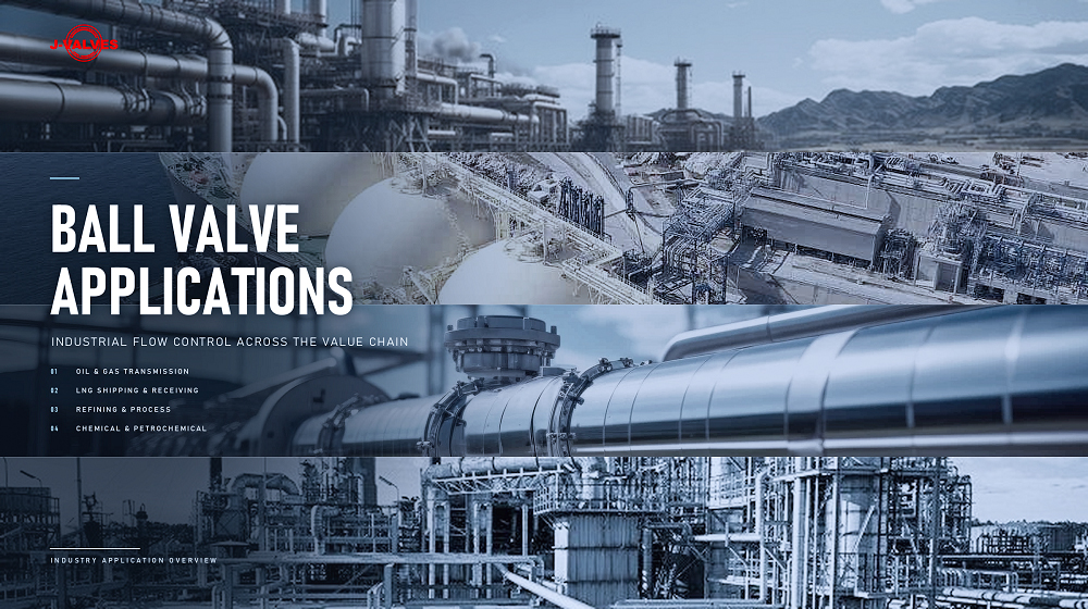
The homes for a 30 inch Class 900 valve are transmission pipelines and their stations, compressor and pump station suction and discharge headers, tank farm mainline isolation, and large gas handling plants. It is a block valve in every one of those duties: it sits open or closed for long periods and is expected to isolate a section completely when it is closed.
Full bore is what qualifies it for a pigged line, and that is the reason the size is written twice in the name. A reduced bore valve of this class and size would be cheaper and lighter, and it would stop every pig in the system. Where the line is pigged, the valve has to be full bore, the bore has to match the pipe, and the drawing has to say so.
The valve is not the answer for every large isolation duty. Above the published temperature the material group has to change; where the medium is wet and corrosive, carbon steel is the wrong body and F316 is the answer; and where the line has to be isolated with two independent barriers and proved by a bleed, the seat arrangement and the cavity provisions decide whether the valve can do it at all.
Installation, Operation and Maintenance
The valve arrives on a pallet or in a crate and is lifted by the lugs on the body, not by the gear or the stem. It is set in place with the pipe ends aligned to the ring grooves, the ring is inserted dry, and the studs are tensioned in a cross pattern to bring the faces together evenly. On a ring joint the gap between the faces is set by the ring, so the studs are not compressing a gasket; they are holding two metal faces against a metal ring.
The valve is then supported. A 30 inch Class 900 body is heavy enough that its own weight plus the pipe load will distort a joint if the support is left to the pipe, and the support is part of the installation rather than a site improvisation. Thermal movement in the line has to be allowed for at the same time, because a support that stops the pipe from moving puts the movement into the valve.
Operation is a quarter turn on the gear, and the position indicator is what the operator reads. Where the valve is fitted with a hydro-pneumatic actuator for line break or emergency shutdown, that actuator is set up against the line's own logic and is tested with it, not separately. Maintenance means isolating, venting, draining, relieving the cavity if the seat is double piston effect, and then breaking the two body joints in a sequence that keeps the ball supported.
How to Specify and Order
Six decisions fix the valve: size and class, flange series, body grade with its examination, seat material and arrangement, operator, documents. The flange series is the one unique to this size and the one most often left out of an enquiry, because buyers are used to writing B16.5 and assuming it covers everything.
Four more questions are about the line: the medium, the design and operating temperature, the design pressure, and whether the line is pigged. The pigging question is what fixes full bore, and the temperature question is what decides whether a PEEK seat is enough or the seat has to be metal, and whether the body grade has to move.
Documents should be named on the order: EN 10204 3.1 for body and trim, the ultrasonic report if A388 was ordered, the shell and seat test records, the dimensional report against the B16.47 series, the fire test certificate with its scope, and the gear or actuator data sheet with its interface. All of them can be supplied, and on a valve of this size none of them should be left to assumption.
FAQ
Q: Why is the flange ASME B16.47 and not ASME B16.5?
A: Because of the size. ASME B16.5 covers flanges from NPS half inch to NPS 24, and a 30 inch flange is outside that scope. ASME B16.47 covers the larger sizes in series A and series B, which differ in bolt circle and outside diameter, so the series has to be named on the order. A valve drilled to the wrong series cannot be bolted to the line, however good the valve is.
Q: Does 30x30 mean anything different from 30 inch?
A: It says the valve is full bore: thirty inches at the flanges and thirty inches through the ball. On a reduced bore valve the two numbers differ, which is why reduced bore sizes are written as pairs such as 4x3. Here they are the same, and that is what allows a pig to pass.
Q: Can this valve be used on a pigged pipeline?
A: Yes, and that is the main reason to buy it in full bore. The passage matches the pipe, the bore is unobstructed in the open position, and the seat does not protrude into the flow. A reduced bore valve of the same class would stop the pig, and no operational procedure gets around that.
Q: Is ultrasonic examination of the forging included?
A: Not by default. Examination to ASTM A388 is a supplementary requirement, which means it appears on the order or it does not happen. On a body and two caps of this size it is worth ordering, because a heavy forging is exactly where an internal discontinuity would sit undetected by a shell test.
Q: Which seat arrangement suits a large liquid line?
A: Single piston effect, unless there is a reason for the alternative. It relieves the thermal expansion of the liquid trapped in a cavity this size into the line on the low pressure side. Double piston effect seals from both directions and is the right choice for a double block and bleed duty, but it needs a relief route for the cavity because it will not relieve itself.


Hot Products


News
Stainless Steel Ball Valve Grades: 304, 316 And 316L, And What Actually Decides
Molybdenum is the difference that decides the duty, carbon is the difference that gets missed, and the chloride in the line matters more than the price.
Read More
Ball Valve Spare Parts for Overseas Projects: The Wear Part List, The Quantity Math, And Four Traps
Why isolation valves fail on calendar time, not cycles. Wear part lists, Poisson stock maths, seat kit traps and the clauses that decide year six.
Read More
Ball Valves On A Bottom Loading Gantry: Creep, Dry Break And The Test That Proves Neither
A loading gantry cycles a ball valve far more than it is designed for and still cannot prove shut-off. Where creep starts, and what to specify.
Read More
Lined Ball Valves in Acid Service: The Liner Does Not Fail, The Steel Behind It Does
The valve came out of the line looking better than most valves that come out of a hydrochloric acid line. Three inch, PFA lined, cast body, Class 150, fourteen months in service on a 32 percent acid transfer duty at 55 to 60 degrees C, about forty open and close cycles a week. The paint was intact.
Read More