

CHINA J-VALVES Offers Various High-quality I ndustrial Ball Valves
J-VALVES, a distinguished professional ball valve manufacturer rooted in China, takes pride in its extensive product portfolio. Our offerings span a wide range, including trunnion-mounted ball valves, floating ball valves, high-temperature ball valves, high-pressure ball valves, metal-sealed ball valves, ultra-low temperature ball valves, DBB ball valves, Three-way And Four-way Ball Valve, and fully welded ball valves. Each product is a testament to our commitment to precision engineering and reliable performance. Meticulously crafted, they are designed to not only meet but exceed the most stringent industrial demands, ensuring stable operation even under extreme conditions. This enables us to provide our clients with high-value services and makes our valves widely sought-after in industries.
Product Category
Contact Us


-
J-VALVES-Q347F
-
J-VALVES
Overview of the J-VALVES 3 piece forged steel flanged trunnion ball valve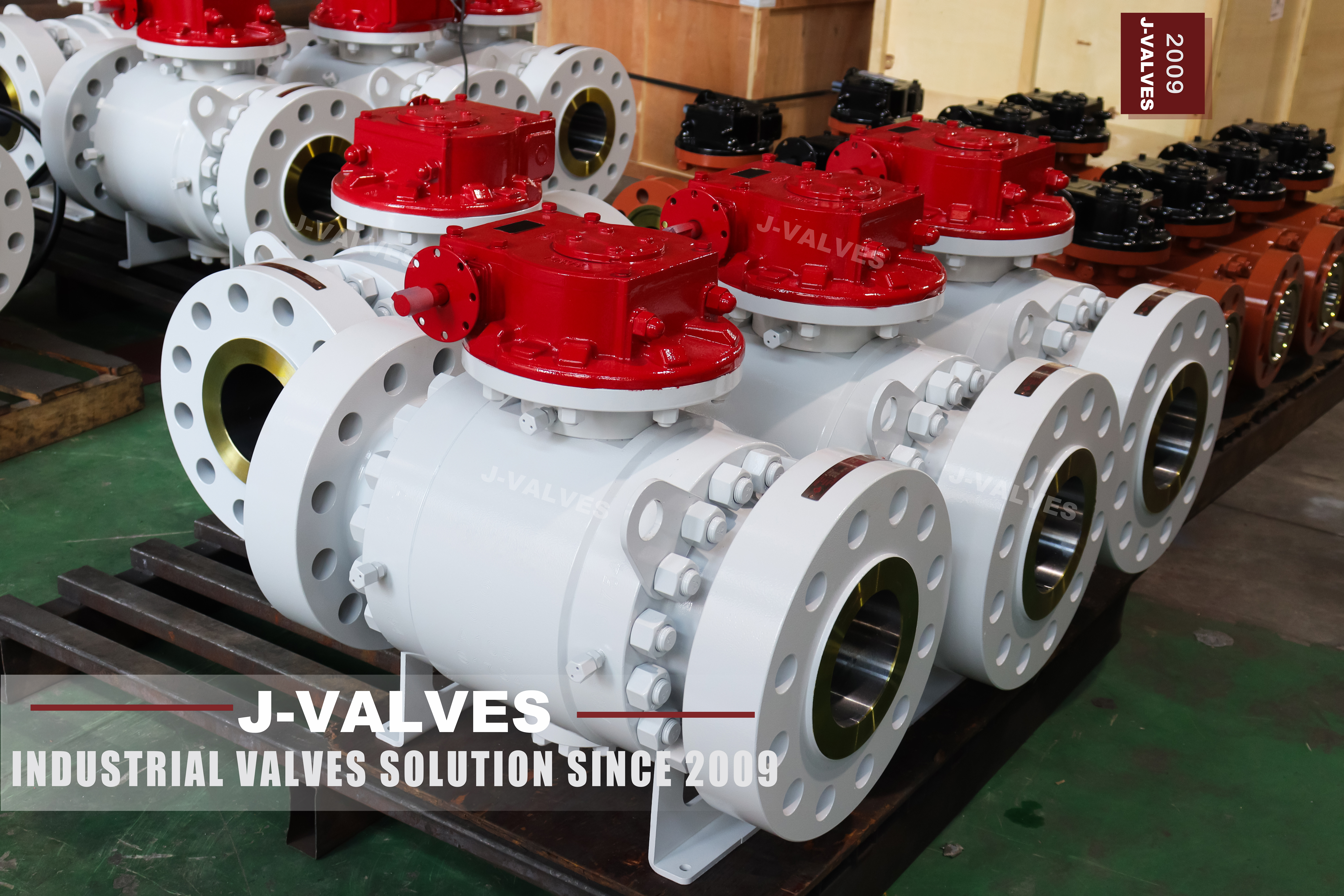
This is the side entry three piece body in forged steel: a centre section that carries both trunnion bearings, two end caps each closed on its own stud ring, flanged ends to ASME B16.5 in raised face or ring joint, and a published range of 2 to 56 inch at Class 150 to 2500. It is the page to start from when the size is not fixed yet, because almost everything on it is a range rather than one valve.
What makes the range readable is a decision that has nothing to do with size: how the seats are arranged. Single piston effect, double piston effect, and the two combined arrangements change what the valve does with the pressure trapped in the cavity, whether both seats are barriers, and whether the cavity can relieve itself into the line. Two valves built on this page with the same size, class and body grade can behave differently in a blocked-in line, in a bleed test and after a fire.
The rest is ordinary but has to be stated. Forged body, trunnion supported ball, anti-static device, fire safe to API 607, low emission stem sealing, and a pressure envelope documented to ASME B16.34 with API 6D as the product standard. The classes above 600 leave API 608 behind, which is the single line most catalogues in this size range get wrong.
Design and Construction
The body is three pieces and the split is what defines the family. The centre section holds the ball, both seats and both trunnion bearings, and it never comes apart in service. The caps carry the flange and the pipe connection and nothing structural beyond their own joint. That is why the stem axis and the lower bearing axis keep their alignment every time a cap comes off, and why the same casting pattern can be drilled for raised face or ring joint without touching the internals.
There is a size break inside the design. Up to 4 inch the ball is held by an upper and a lower trunnion housed in the primary body, and 6 inch and larger the bearings move into two separate bearing blocks. The break is not a marketing division: at the smaller sizes the bearing boss can be machined into the body wall, and above it the bearing has to sit in a block that can be machined, bored and preloaded on its own.
The trunnions take the side load that line pressure puts on the ball, so the stem never sees it and the seat does not have to hold the ball against the flow. The bearings themselves are metal backed and self-lubricating, which is the reason a large valve in this family can still be turned by a gearbox rather than an actuator.
Three openings cross the pressure boundary on every valve and they are worth counting. The joint under each end cap is one, the stem bore with its packing is the second, and the screwed NPT plug low on the body is the third. That plug is the drain, and up to 4 inch the drain and the vent share the one port.
Seat injection is the last structural item. From 6 inch the emergency seat injection fitting is standard rather than optional, with a needle valve and a non-return check screwed into the body and connected to the seat rings; on 2 to 4 inch it can be supplied as an option, and below 6 inch the injection point can be put in the body cavity instead. It buys time, not a repair.

Material Options
The default body is A105 forged carbon steel, and for most of the range that is the correct answer: it is strong, it is cheap, and it is weldable. A350 LF2 is the low temperature version of the same idea and is specified when the line runs cold enough that impact toughness has to be guaranteed rather than assumed. A182 F304 and F316 are the stainless options, and the difference between them is molybdenum and therefore chlorides. F51 and F53 duplex, and the nickel alloys, are for media that would eat any of the austenitic grades.
Nothing in that list raises the class. A 2500 class valve in F316 is read in group 3.1 of ASME B16.34, not in the carbon column, and the two columns do not give the same number at the same temperature. Buyers who upgrade the body for corrosion sometimes assume the upgrade also buys pressure margin; it does not, and on a range page that spans four classes the point has to be made once and clearly.
| Component | Standard Material | Optional Upgrade | Service Notes |
|---|---|---|---|
| Body and end caps | ASTM A105 forging | A350 LF2 for low temperature; A182 F304 or F316 for corrosion; F51 or F53 duplex | Forged to shape, no cast skin |
| Ball | Forged steel base with ENP | Hard chrome; tungsten carbide coating; cobalt based hard facing | The coating is a wear surface, not a corrosion answer |
| Trunnion and supports | Forged steel, surface hardened | 17-4PH precipitation hardening stainless | Blocks from 6 inch upward |
| Stem | 17-4PH stainless | A105 with ENP; F316; nickel based alloy for sour service | Blowout proof, retained by the body |
| Seat | PTFE or reinforced PTFE at the low end | PPL, PEEK, metal with flexible graphite | The seat sets the valve temperature, not the body |
| Body joint gasket | Flexible graphite spiral wound | Metal ring joint gasket, octagonal or oval | One per joint, two per valve |
| Bolting | A193 B7 with A194 2H nuts | B8 or B8M with 8 or 8M nuts | Stainless bolting on a carbon body is a choice, not an upgrade |
| Body plug | Carbon steel, NPT | F316 for corrosive service | Drain on all sizes, vent shared up to 4 inch |
Technical Specifications
The table fixes what a standard fixes, and it is deliberately short of the numbers that belong to a drawing. Size, class, body style, ends, facing, the test regime and the documents can all be checked against a catalogue and against the certificate that arrives in the crate. Wall thickness is a calculation under ASME B16.34 and belongs to the design record. Face to face is the ASME B16.10 value for the size and class ordered, and the GA drawing is where it gets confirmed.
That distinction matters more on a range page than on a single spec page, because a range invites the reader to assume that every combination in it has already been dimensioned. It has not. The range says what can be built; the drawing says what the valve in the crate actually measures, and on reduced bore and special bore builds the drawing is the only place the bore is written down.
| Item | Value |
|---|---|
| Size range | 2 to 56 inch, DN50 to DN1400 |
| Pressure class | Class 150 to 2500, PN20 to PN420 in the API 6D designation |
| Body style | Three piece forged body, side entry, trunnion mounted ball |
| Body material | ASTM A105 as standard; A350 LF2, A182 F304 or F316, F51 or F53 on request |
| End connections | Flanged raised face or ring joint to ASME B16.5; butt weld to ASME B16.25 |
| Face to face | ASME B16.10 for the size and class, confirmed on the signed GA drawing |
| Bore | Full bore or reduced bore to the API 6D table, special bore on request |
| Seat arrangement | Single piston effect standard; double piston effect or combined DIB on request |
| Temperature | Minus 29 to plus 425 C as published for the range; the seat sets the working limit inside it |
| Stem | Keyed, blowout proof, anti-static, low emission packing to ISO 15848 |
| Operator | Lever, worm gear, pneumatic, electric, hydraulic or gas-hydraulic |
| Painting | Sky blue RAL 5015 as standard, other systems on request |
| Product standard | API 6D; API 608 applies only up to Class 600 |
Standards and Compliance
ASME B16.34 supplies the two things a pressure boundary needs: the minimum wall for the size and class, and the allowable stress that turns a class into a pressure at a temperature. It does this through material groups, which is why the same class number means slightly different pressures on a carbon body and on an austenitic one. A range that crosses four classes and five material families is really a grid, and the grid is in the standard rather than on any catalogue page.
API 6D is the product standard for the pipeline valve in this family, and it is the one that governs marking, documentation, cavity and drain provisions, and the test regime on top of the dimensional standards. API 608 is the standard most soft seated ball valve data sheets quote, and its scope stops at Class 600. On this page that means the 150 and 300 and 600 class valves can be described under either, and the 900, 1500 and 2500 class valves cannot be described under 608 at all.
Fire safety and emissions are type tests rather than per valve tests, and both have a scope. API 607 and ISO 10497 are the same test written twice, and API 6FA has been folded into 607, so quoting all three on one certificate is quoting one test three times. Low emission sealing is certified to ISO 15848 with a class and a stem seal arrangement attached; without that class the phrase low emission is a description, not a result.
| Requirement | Standard | What J-VALVES Supplies |
|---|---|---|
| Wall thickness and rating | ASME B16.34, material group per grade | Design calculation, rating from the group table |
| Pipeline valve requirements | API 6D | Marking, documentation, cavity and drain provisions |
| Soft seated ball valves | API 608, DN15 to DN600 and Class 150 to 600 only | Applies to the lower part of the range, not the upper |
| Pressure testing | API 598 | Shell at 1.5 times, seat at 1.1 times the rating |
| Fire test | API 607, with ISO 10497 as the equivalent | Type test certificate with a size and class scope |
| Low emission | ISO 15848 | Stem seal arrangement certified with a class and a test report |
| Flange dimensions | ASME B16.5 | Raised face or ring joint cut to the facing ordered |
| Face to face | ASME B16.10 | Table value confirmed on the signed GA drawing |
| Material certificate | EN 10204 3.1 | Body, ball, stem and seat, heat number matched to the marking |
Manufacturing Process
Every body in this range starts as a forging. A billet is cut, heated, upset and punched, then the shape is machined out of solid material, which is why there is no cast skin on any photograph in this family and why the surface is uniform across the whole body. The consequence for the buyer is a dense grain structure and no shrinkage porosity; the consequence for the supplier is machining time, because a forging arrives close to size but not at size.
The three pieces are machined as a set and that is the operation that decides whether the valve is good or merely acceptable. Bore, seat pockets and joint faces are all machined with each cap located on its own spigot, so the seats end up concentric with the ball once the valve is back together. Two valves that look identical from outside can differ by how much care went into that one set-up, and no photograph taken after painting will show it.
Assembly follows the machining in a fixed order: seats and springs into the centre section, ball between them, caps landed, studs brought up in stages in a cross pattern, then test, drain, dry and mask. The masking step is small and consequential, because paint on a raised face or in a ring joint groove will produce a leak on site that gets blamed on the gasket.

Quality Control and Testing
Eight checkpoints sit on every valve and the paperwork travels in the crate. Identity comes first: the heat number on the body has to match the mill certificate, and when the order asks for it a PMI reading confirms that body, ball and stem are the grades the paper claims. On an austenitic build this is not a formality, because 304 and 316 are indistinguishable on a bench.
| Step | What Is Checked | Standard or Acceptance |
|---|---|---|
| 1 Material | Heat number against the mill certificate, chemistry and tensile | Grade ordered, EN 10204 3.1 |
| 2 Identity | PMI on body and trim when ordered | No mixed parts |
| 3 Dimensional | Flange facing, bolt circle, face to face, bore | ASME B16.5, B16.10, API 6D bore table |
| 4 Machining | Seat pocket concentricity, joint face flatness, groove profile | Drawing tolerance |
| 5 Shell test | Body and both body joints at 1.5 times the rating | API 598, no leakage |
| 6 Seat test | Each seat separately at 1.1 times the rating, cavity vented | API 598; zero visible leakage on soft seats |
| 7 Function | Quarter turn operation, position indication, anti-static continuity | Works standard |
| 8 Final | Cavity drained, bore dried, faces masked, paint, end caps fitted | Works standard |
The shell test is where a three piece body differs from a two piece one in practice, because there are two joints to hold at full pressure at the same time. A joint that weeps in the test bay is a machining or a torque problem; a joint that weeps on site is a shutdown. The seat test is run seat by seat with the cavity vented, so the result is two numbers rather than one impression, and on a metal seated build the acceptance is the leakage rate the standard tabulates rather than zero.

Applications and Industry Service
The ordinary homes for this range are oil and gas gathering, transmission and processing lines, refinery and petrochemical piping, and the larger water and utility headers where a full bore valve has to pass a pig. It is also the default choice for block valve duty on a line that will sit in one position for months and then be asked to isolate perfectly, which is the duty a soft seated trunnion valve does best.
Where the valve is welded in, or where the cavity has no other route to relieve, the seat arrangement has to change. A double piston effect seat seals with pressure from either side, which is what a double block and bleed check and a welded body both want, but it also means the cavity cannot relieve itself into the line, so the design has to provide for relief. Choosing double piston effect because it sounds stronger is how a valve ends up needing a relief device nobody ordered.
The range is not the right answer everywhere. Below the published temperature floor the seat and the gasket become the problem rather than the body, and a cryogenic valve is a different build with an extended bonnet. Above the published ceiling the body grade has to change before the seat does. Where the medium attacks carbon steel the answer is a higher alloy, and where it attacks 316 the answer is duplex, not a thicker wall.
Installation, Operation and Maintenance
Support the valve and align the flanges before any stud is tightened, particularly above 12 inch where the valve weight is a load on the pipe rather than on itself. On a ring joint facing the ring goes in dry and sits in the groove, and the studs are tensioned to bring the faces together evenly rather than to compress anything. A ring that has already been compressed once should not go back in.
In service the valve turns a quarter turn and the indicator on the gear or the lever shows the position. Because the body retains the stem, it cannot be blown out, which is what allows the packing to be adjusted with the line live and the upper seal to be renewed once the cavity has been vented. Neither body joint can be touched with the line live, since both are under full pressure around the entire circle.
For maintenance the caps come off, the ball and both seats come out, and the pipe stays where it is. Before that the line has to be isolated and the body vented and drained; afterwards two joints have been opened and have to be re-gasketed and re-torqued in the cross pattern. On a double piston effect build the cavity also has to be relieved before the caps are broken, which is the step that gets forgotten when the same crew is used to working on single piston effect valves.
How to Specify and Order
Six decisions make the valve: size and class, body grade with its certificate, end connection and facing, bore, seat arrangement, operator. Four of those are usually missing from the first enquiry, and the two most often missing are the seat arrangement and the bore, because both can be left to the supplier and both change what the valve does.
Four more questions are about the line rather than the valve: the medium, the design and operating temperature, the design pressure, and how the valve will be operated and how often. Medium picks the grade, temperature picks the seat, pressure picks the class, and duty picks between a lever, a gear and an actuator.
Documents should be named on the order rather than assumed: EN 10204 3.1 for body and trim, the hydro test record, the dimensional report, the fire test certificate with its size and class scope, and the low emission report with its class if that claim is being made. All of them can be supplied. None of them are in the default delivery, which is exactly why the purchase order has to say so.
FAQ
Q: Which seat arrangement should be ordered, single or double piston effect?
A: Single piston effect is the default and it relieves a cavity that has been heated into the line on the low pressure side, which is what most liquid and gas block valves want. Double piston effect seals from both directions and is the arrangement to order when the valve is welded in, when a double block and bleed check has to prove both seats, or when the cavity has no other relief route. It is not a stronger version of the standard seat; it is a different rule about where the cavity pressure goes.
Q: Can a Class 900 valve on this page be described as API 608?
A: No. API 608 covers flange sizes DN 15 to DN 600 and classes 150 to 600, so the 150, 300 and 600 class valves in this range can be quoted to it and the 900, 1500 and 2500 class valves cannot. Those are built and documented to API 6D, and the certificate set that comes with them is the 6D set rather than the 608 one.
Q: What does the size break at 4 and 6 inch actually change?
A: Where the trunnion bearings live. Up to 4 inch the upper and lower bearings are housed in the primary body, and from 6 inch they move into two separate bearing blocks. It also changes the standard fittings: emergency seat injection is standard from 6 inch and optional below it, and the drain and vent share one port up to 4 inch.
Q: Is the metal seat option a way to raise the temperature range?
A: Not on its own. The published range for this family stops at plus 425 C, and the seat table offers a metal seat with flexible graphite to a much higher figure. Those two lines describe different things: the range is the body, the seat figure is the seat material. A seat that survives a temperature does not extend the range of the body it is fitted to.
Q: Does a three piece body mean the valve can be serviced under pressure?
A: No. Both body joints are pressure boundaries and both see full line pressure around the whole circle, so the caps cannot be broken until the line is isolated and the cavity is vented and drained. What the three piece body gives is access: the ball and seats come out with the pipe left in place, and two joints then have to be re-gasketed and re-torqued.


Hot Products


News
Stainless Steel Ball Valve Grades: 304, 316 And 316L, And What Actually Decides
Molybdenum is the difference that decides the duty, carbon is the difference that gets missed, and the chloride in the line matters more than the price.
Read More
Ball Valve Spare Parts for Overseas Projects: The Wear Part List, The Quantity Math, And Four Traps
Why isolation valves fail on calendar time, not cycles. Wear part lists, Poisson stock maths, seat kit traps and the clauses that decide year six.
Read More
Ball Valves On A Bottom Loading Gantry: Creep, Dry Break And The Test That Proves Neither
A loading gantry cycles a ball valve far more than it is designed for and still cannot prove shut-off. Where creep starts, and what to specify.
Read More
Lined Ball Valves in Acid Service: The Liner Does Not Fail, The Steel Behind It Does
The valve came out of the line looking better than most valves that come out of a hydrochloric acid line. Three inch, PFA lined, cast body, Class 150, fourteen months in service on a 32 percent acid transfer duty at 55 to 60 degrees C, about forty open and close cycles a week. The paint was intact.
Read More