

CHINA J-VALVES Offers Various High-quality I ndustrial Ball Valves
J-VALVES, a distinguished professional ball valve manufacturer rooted in China, takes pride in its extensive product portfolio. Our offerings span a wide range, including trunnion-mounted ball valves, floating ball valves, high-temperature ball valves, high-pressure ball valves, metal-sealed ball valves, ultra-low temperature ball valves, DBB ball valves, Three-way And Four-way Ball Valve, and fully welded ball valves. Each product is a testament to our commitment to precision engineering and reliable performance. Meticulously crafted, they are designed to not only meet but exceed the most stringent industrial demands, ensuring stable operation even under extreme conditions. This enables us to provide our clients with high-value services and makes our valves widely sought-after in industries.
Product Category
Contact Us


-
J-VALVES-Q347F
-
J-VALVES
Overview of the J-VALVES 4x3 Inch 1500LB A105N Trunnion Ball Valve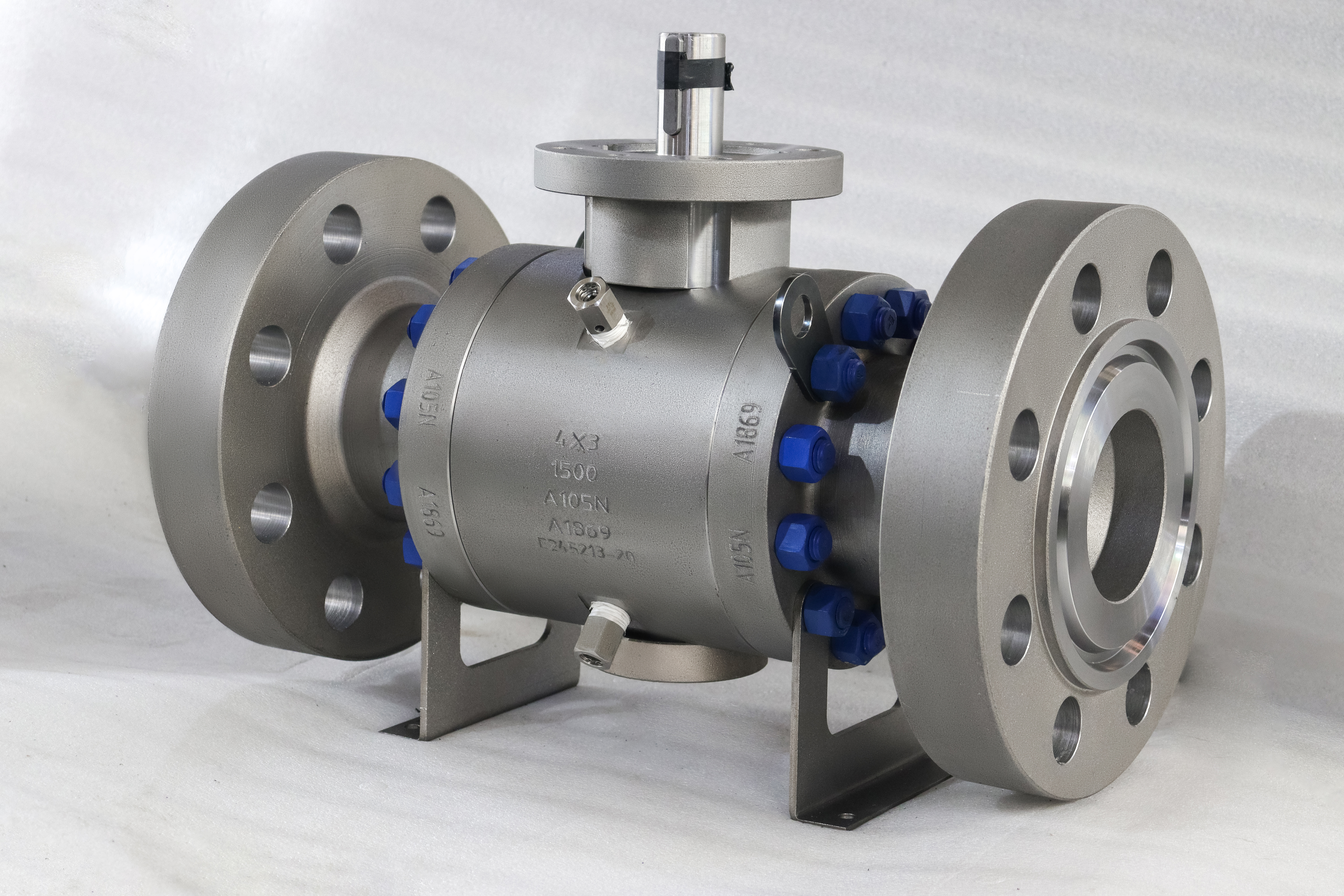
The page argues for the reduced bore with two numbers: weight down by about twenty percent and torque down by fifteen. Neither of them comes with a drawing, a test report or a stated basis, and a percentage without a basis is not a saving, it is a comparison against something the reader cannot see. Compared with the full bore valve of the same end size the figure is one thing; compared with a three inch valve of the same bore it is another, and the page does not say which one it means.
What the valve actually fixes is simpler and can be checked. The ends are four inch, so the flange, the bolting pattern, the wall of the end caps and the face to face length are all four inch items. The bore is three inch, so the ball, the two seats, the trunnions and the torque to turn it are three inch items. A reduced bore valve is two sizes in one body, and every question about cost, weight or torque has to say which of the two it is talking about.
This page is about that distinction. It does not repeat the argument about how the size designation is read, and it does not reopen the pressure code. It takes the saving the page claims, explains why a percentage cannot be quoted as a specification, and sets out what a buyer should ask for instead when weight or torque actually matters to the installation. That list is short, and it is the same list whether the valve is four by three or six by four.
Design and Construction
The body is three pieces: a centre section carrying the stem and both seats, and an end cap bolted to each side on a ring of studs. The layout exists so that the middle section can be taken out, and the middle section is where the ball and both seats live. On a reduced bore valve that middle section is sized around a three inch ball even though the caps around it carry four inch flanges, which is the physical reason the weight saving is not proportional to the bore.
The ball runs on an upper and a lower trunnion rather than on the seats, so line pressure is taken by the trunnions and the seats only have to seal. At this class the loads are high enough that the trunnions run in bearing blocks rather than in the body material, and the ball turns on them instead of being pressed into the downstream seat. That is what keeps the operating torque predictable at a pressure where a floating ball would be pressed hard enough to be difficult to move.
The stem is separate from the ball and does not carry the side load from line pressure. It is retained by the body cover with an anti blowout shoulder, and the gland and packing sit above that shoulder, so the shoulder holds the stem and not the gland. The operator is a gearbox as standard at this class, because the torque at fifteen hundred pounds is past what a lever should be asked to deliver by hand.

Material Options
The body is forged carbon steel, A105N, which is the normalized condition of the plain carbon forging grade. The ball is A105N with a nickel deposit, a hard chrome deposit or a welded overlay, and the trunnions and stem are either surface hardened A105N or a precipitation hardening stainless. Those codes are what the plate carries; where a medium needs a different family, that is a question for the certificate rather than for the product title, and the order should say which certificate grade it expects to receive.
The seat list runs from PTFE through reinforced PTFE and PPL to PEEK and a metal seat with a graphite seal, and each one sets a ceiling below the figure printed for the body. The joint gasket is a ring joint in soft iron, low carbon steel or a stainless grade, and the ring is a consumable that is renewed every time a joint is opened. The bolting is an alloy steel stud with a matching nut, or a stainless stud where the site is wet, and the nut has to be paired with the stud rather than chosen by size.
| Component | Standard Material | Optional Upgrade | Service Notes |
|---|---|---|---|
| Body | forged carbon steel, A105N | on the order | code on the plate |
| End cap joints | two bolted joints with ring gaskets | soft iron, low carbon or stainless ring | renewed at every break |
| Ball | A105N | nickel, chrome or welded overlay | three inch, inside a four inch cap |
| Trunnion | surface hardened A105N or 17-4PH | runs in bearing blocks at this class | takes the side load |
| Stem | 17-4PH or A105N with a nickel deposit | on the order | anti blowout shoulder above the gland |
| Seat | PTFE | reinforced PTFE, PPL, PEEK or metal with graphite | sets the temperature ceiling |
| Ring gasket | soft iron | low carbon steel or a stainless grade | one use only |
| Bolting | alloy steel studs with matching nuts | stainless studs for wet sites | nut paired with the stud |
| Operator | gearbox | pneumatic, electric or hydraulic | standard at this class |
Technical Specifications
Three numbers describe this valve and they do not come from the same place. The class, written as PN 250 in the API 6D pressure code list, and the four inch end size, together give the flange, the bolting and the installed length, which is the figure ASME B16.10 prints for that size at that class. The third number is the three inch bore, and it comes from the bore column rather than from the size. A quotation that starts with the bore and works outward gets the flange wrong.
The temperature range is minus 29 to plus 425 Celsius measured as metal temperature. That range belongs to the body, and the part that narrows it is the seat: a soft seat stops well before the top of it, and the metal seat with a graphite seal is the only one that reaches it. The pressure and temperature ratings themselves come from the table in the pressure boundary standard for the material group the body belongs to, and they are read from that table rather than converted from the class number.
| Item | Value |
|---|---|
| Nominal size | 4x3 inch, four inch ends with a three inch bore |
| Pressure class | class 1500, written as PN 250 in the API 6D code list |
| Body style | three piece, two bolted body joints |
| Ball support | trunnion mounted, upper and lower |
| Bore | reduced bore, three inch inside four inch ends |
| Body material | forged carbon steel, A105N, code as stamped |
| Heat treatment | normalized, recorded against the heat number |
| Ball material | A105N |
| Ball surface | nickel deposit, hard chrome or a welded overlay |
| Trunnion material | surface hardened A105N or 17-4PH |
| Stem material | 17-4PH or A105N with a nickel deposit |
| Seat material | PTFE as standard |
| Seat options | reinforced PTFE, PPL, PEEK or metal with graphite |
| Ring gasket | soft iron, low carbon steel or a stainless grade |
| Bolting | alloy steel studs with matching nuts, stainless on request |
| End connection | ring joint flange to ASME B16.5, weld ends to ASME B16.25 on request |
| Face to face | ASME B16.10, the four inch length for this size and class |
| Design standard | API 6D, with ASME B16.34 and API 608 underneath |
| Test standard | API 598 or API 6D |
| Shell test | one and a half times the rating |
| Seat test | one and a tenth times the rating, both directions |
| Temperature range | minus 29 to plus 425 Celsius, metal temperature |
| Temperature ceiling | set by the seat and the packing, not by the body |
| Operation | gearbox as standard at this class |
| Anti blowout | stem retained by the body cover |
| Weight and torque | to the approved drawing when measured, never as a percentage |
| Pigging note | a reduced bore of this kind is not a pigging valve |
Standards and Compliance
The page names the pipeline specification, the pressure boundary standard and the general ball valve standard, and all three apply in part. The pipeline specification governs the design, the marking and the test for a valve of this kind; the pressure boundary standard supplies the rating and the minimum wall; the general standard overlaps both. Where an order cites all three it should also say which one prevails, because a certificate written to one is not evidence for the others.
Testing is to the pipeline specification or to the general test standard, and both apply the same multiples: one and a half times the rating for the shell and one and one tenth for the seat, each in both directions. None of that changes with the bore. What does change is the acceptance on the seat, which follows the seat material rather than the class, and the record has to say which acceptance was applied or the certificate cannot be read by anyone who was not at the bench.
| Requirement | Standard | What J-VALVES Supplies |
|---|---|---|
| Pipeline valve | API 6D | design, marking and test |
| Pressure boundary | ASME B16.34 | rating, minimum wall, material group |
| General ball valve | API 608 | overlapping requirements |
| Flange | ASME B16.5 | ring joint, class 1500 |
| Face to face | ASME B16.10 | the four inch length, because the ends are four inch |
| Weld ends on request | ASME B16.25 | butt weld preparation |
| Testing | API 598 or API 6D | 1.5 times shell, 1.1 times seat |
Manufacturing Process
The body starts as a forging, is normalized, and is then machined from the flange faces inward so that the bore, the seat pockets and the trunnion bores come off one reference. On a reduced bore body the step from the four inch end to the three inch bore happens inside the end cap, and that transition is machined rather than formed, because a cast or forged step left rough is a place where the flow turns and where a tool would have to be dressed by hand.
Closing the body is a torqued operation rather than a tightened one. The ring sits in its groove, the cap goes on, and the studs are brought down in a cross pattern so that the joint closes evenly; a joint closed from one side loads the ring on one edge, passes a cold shell test and leaks after a few thermal cycles. The studs are lubricated before assembly, because a dry stud takes the torque in friction instead of in preload, and the wrench reading then means nothing.

Quality Control and Testing
The certificate is written against the heat number stamped on the plate, and a material identification report is issued against the same heat when the order asks for one. On a forged carbon steel valve this is the check that separates a normalized forging from an as forged one, because the two look the same and only the record and the impact test tell them apart. The plate code is read at goods in and the certificate follows the plate.
The shell test is run at one and a half times the rating with both body joints assembled, so the wall and the joints are proved together. The seat test follows at one and one tenth times in both directions with the cavity monitored, and the acceptance follows the seat material. A valve that passes the shell and leaks into the cavity has failed the seat test even though the body held, and the record should show which of the two was being judged.
The dimensional check is where a reduced bore valve is either right or wrong, because two sizes meet in one body. The flange is checked against the four inch class 1500 table, the face to face against the length for that size, and the bore against the three inch dimension. Weight and torque are only recorded when they have been measured on that valve, and a figure on a certificate that was calculated rather than measured is a figure that cannot be defended later.
| Step | What Is Checked | Standard or Acceptance |
|---|---|---|
| Forging | heat number and certificate | normalized condition on the record |
| Material identity | report against the same heat | quoted when the order asks |
| Bore | measured to the three inch dimension | the step is machined, not formed |
| Flange | measured to class 1500, four inch | ring groove included |
| Face to face | measured to the four inch length | not a three inch length |
| Shell test | wall and both joints at 1.5 times | run with the joints assembled |
| Seat test | both directions at 1.1 times | cavity monitored |
| Weight and torque | recorded only when measured | never calculated onto a certificate |

Applications and Industry Service
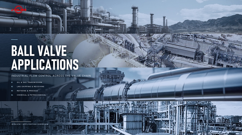
A valve of this shape belongs where the line is four inch, the pressure is high, and the flow does not need the full bore: high pressure injection, letdown, well service manifolds and the isolation points on a line that runs at a fraction of its capacity most of the time. In those duties the reduced bore costs a pressure drop across the valve and returns a smaller ball, a smaller seat and a lower torque, which is the trade the page is advertising without ever stating it in those terms.
It is the wrong valve where the line has to be pigged, and the page says so itself when it notes that the design suits systems that do not require full bore pigging. It is also the wrong choice where the pressure drop matters more than the torque, and where the spare parts have to be common with a full bore valve of the same size, since the ball, the seats and the trunnions are three inch parts and will not interchange with a four inch valve.
Installation, Operation and Maintenance
The valve is installed with the gear box accessible and the cavity drain pointing down, because the drain is how the cavity is emptied and sampled. A gear operated valve is not a hand valve with a handle: the gear has a ratio, and the number of turns to go from open to closed is a property of that ratio, so the indicator on the gear, not the position of a lever, is what says where the ball is. On a buried or lagged line the gear should be brought up to the surface rather than reached through a hatch.
In service the seat injection fittings, where they are fitted, push sealant to a passing seat ring and hold a line until the next planned stop. They do not restore a seat. A seat change means the line is isolated, the cavity vented, both joints released and the middle section taken out, and the joints go back on new ring gaskets. That is the moment to check the ball as well, because a new seat against a worn ball is a pair that was never matched.
How to Specify and Order
The order has to name the size in both dimensions, the class, the flange facing, the body code, the ball surface, the seat, the packing, the operator, the test standard and the certificate grade. For this valve the size line is the one that gets written badly: four by three is two dimensions and both have to appear, with the ends named as four inch and the bore named as three inch, so that nobody has to guess which one the buyer meant.
Then decide what the weight and torque figures are for. If they are needed for a lifting plan or an actuator sizing, ask for them on the approved drawing, measured on the valve that is being supplied. If they are not needed, leave them off, because a percentage in a quotation becomes a number in a specification and then a claim that nobody can support. The enquiry line is short: bore and end size both stated, weight and torque to the approved drawing, no percentages.
FAQ
Q: Is the weight saving on a reduced bore valve 20 percent?
A: Not as a specification. The page states two percentages without saying what they are measured against, and against a full bore valve of the same end size the figure is one thing while against a three inch valve it is another. Where weight matters for a lifting plan, ask for it on the approved drawing for the valve being supplied. Where it does not, leave it off the order.
Q: What exactly is three inch and what is four inch on this valve?
A: The ends are four inch: the flange, the bolting pattern, the end cap wall and the face to face length. The bore is three inch: the ball, the two seats, the trunnions and the torque needed to turn it. That is the whole of the reduced bore idea, and every question about weight, cost or spare parts has to say which of the two it is asking about.
Q: Can a pig pass through this valve?
A: No, and the page says so itself when it notes that the design suits systems that do not require full bore pigging. A three inch bore inside a four inch line leaves a step that a pig will not pass, and the step is also where debris collects. If the line is pigged, the valve for it is a full bore valve of the line size, not this one.
Q: Why is the operator a gear box rather than a lever?
A: Because of the torque at class 1500. A lever is a hand tool for a torque a person can produce comfortably, and at this pressure a four inch valve is past that. The gear box has a ratio, so the number of turns from open to closed follows the ratio and the indicator on the gear, rather than the position of a handle, tells the operator where the ball is.
Q: Does the reduced bore change the pressure rating?
A: No. The rating comes from the class and the material group in the pressure boundary table, and the bore does not enter it. What the reduced bore changes is the flow area, the torque, the weight and the size of the trim, which is why the saving is real even though it cannot be quoted as a percentage without a basis.
Q: What should the size line on the order say?
A: Both dimensions, in the order the valve is built: four inch ends, three inch bore, written so that nobody has to infer which is which. Add the class once, the facing, the body code, the seat, the operator and the test standard. If a weight or a torque is needed, ask for it on the drawing rather than accepting a figure in a quotation.


Hot Products


News
Ball Valves On A Bottom Loading Gantry: Creep, Dry Break And The Test That Proves Neither
A loading gantry cycles a ball valve far more than it is designed for and still cannot prove shut-off. Where creep starts, and what to specify.
Read More
Lined Ball Valves in Acid Service: The Liner Does Not Fail, The Steel Behind It Does
The valve came out of the line looking better than most valves that come out of a hydrochloric acid line. Three inch, PFA lined, cast body, Class 150, fourteen months in service on a 32 percent acid transfer duty at 55 to 60 degrees C, about forty open and close cycles a week. The paint was intact.
Read More
Ball Valves in Amine CO2 Capture: Heat Stable Salts, Rich Amine, And The Three Places The Body Thins
Rich amine at 110 C with heat stable salts is where capture plant ball valves fail. Materials, velocity limits, cavity gas and seat choice, with numbers.
Read More
Fail-Safe Ball Valve Actuators: Spring Return, Stored Air, And The Torque Nobody Checks
Spring return or stored air? The answer is a torque curve, not a datasheet box. Sizing, receiver volume, closing time and four silent failures.
Read More