

CHINA J-VALVES Offers Various High-quality I ndustrial Ball Valves
J-VALVES, a distinguished professional ball valve manufacturer rooted in China, takes pride in its extensive product portfolio. Our offerings span a wide range, including trunnion-mounted ball valves, floating ball valves, high-temperature ball valves, high-pressure ball valves, metal-sealed ball valves, ultra-low temperature ball valves, DBB ball valves, Three-way And Four-way Ball Valve, and fully welded ball valves. Each product is a testament to our commitment to precision engineering and reliable performance. Meticulously crafted, they are designed to not only meet but exceed the most stringent industrial demands, ensuring stable operation even under extreme conditions. This enables us to provide our clients with high-value services and makes our valves widely sought-after in industries.
Product Category
Contact Us


-
J-VALVES-Q347F
-
J-VALVES
Overview of the J-VALVES API6D 600LB A105 Three Piece Trunnion Ball Valve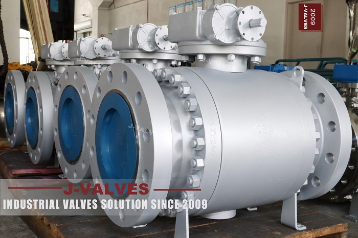
The end preparation on this valve is written as one line and it decides three things that a flanged valve never asks about. A welded end needs a transition piece where the pipe and the valve end do not match, it needs a welding procedure and a qualified welder, and it needs a pressure test that includes the weld rather than stopping at the body. A flanged valve needs none of that, which is why the line is usually the last one filled in.
The second consequence is structural. Once the ends are welded the valve cannot be lifted out of the line, so the three piece body is no longer a convenience but the only way in: the centre section comes out between two welds that nobody intends to cut. That is the argument for this body style on a welded line, and it is also the reason the order has to say who owns the weld and who tests it.
Design and Construction
The body is three pieces: a centre section carrying the ball and the trunnions, and an end piece on each side. On a flanged valve the end pieces are flanges; here they are weld necks, machined to the profile in ASME B16.25 with a bevel that matches the pipe wall. The body joint between the centre and each end piece is still bolted and still a pressure boundary, whatever happens at the far end of the neck.
The weld neck is where the two systems meet. The bore of the neck has to match the bore of the pipe closely enough that the root pass is not bridging a step, and the wall thickness at the bevel has to be close enough to the pipe wall that the joint can be welded without a step change in cooling. Where they do not match, a transition piece is the answer, and that is a part somebody has to supply.
The stem enters through the body and is retained by the cover with an anti blowout shoulder, and the ball runs on an upper and a lower trunnion. None of that changes with the end form, and that is the point: the end form is the only part of this valve that is decided by the pipeline rather than by the valve. It is also the part that cannot be altered after the body is machined.

Material Options
The body is forged A105 carbon steel. A105 is the grade as forged, and where a normalized condition is required the order writes A105N, which is the same grade after a different heat treatment. The plate carries one of them and the certificate follows the plate. A350 LF2 is the low temperature alternative and A182 F316 the stainless upgrade, and both change the weldability question rather than only the corrosion question.
The ball is A105 with a nickel deposit, a hard chrome deposit, a tungsten carbide coating applied by a thermal spray process, or a cobalt alloy overlay. The overlay is the one that changes the seat story, because a hardfaced ball is normally paired with a metal seat and judged on a leakage rate rather than on zero leakage. The coating is named on the order; a page that lists four finishes has not chosen one.
The seat runs from PTFE through reinforced PTFE, PPL and PEEK to metal with a graphite seal, and the packing is wire reinforced graphite. On a welded line the seat matters more than on a flanged one, because the valve cannot be swapped out to fix a seat that was chosen for the wrong temperature. The seat and the packing together set the ceiling, well below the body range.
| Component | Standard Material | Optional Upgrade | Service Notes |
|---|---|---|---|
| Body | forged A105 carbon steel | A105N, A350 LF2 or A182 F316 | code as stamped |
| Body style | three piece, two bolted joints | no | the only way in on a welded line |
| End form | butt weld to ASME B16.25 | flanged to ASME B16.5 | two different valves |
| Pup piece | not supplied as standard | welded on by the maker when ordered | supplied or not, in writing |
| Ball | A105 with nickel, chrome or tungsten carbide | cobalt alloy overlay | overlay pairs with a metal seat |
| Trunnion | surface hardened A105 or 17-4PH | no | upper and lower |
| Stem | 17-4PH or A105 with a nickel deposit | no | anti blowout, retained by the cover |
| Seat | PTFE | reinforced PTFE, PPL, PEEK or metal with graphite | sets the temperature ceiling |
| Operator | worm gear at large size | pneumatic, electric or hydraulic | gear is the default here |
Technical Specifications
Class 600 is written as PN 100 in the API 6D pressure code list, and the two describe one rating. The page gives a size range from half an inch to 56 inch rather than a size, which is a catalogue statement rather than a product one: a valve is ordered at one size, to one drawing. This page is written around the DN250 drawing, the size the rest of this family is published at, and the range only tells a buyer what else the works can make. The order has to name its own size before anything else here means anything.
The weld end is to ASME B16.25, and the drawing has to carry the pipe outside diameter, the wall thickness and the material, because the bevel is cut to match them. Where the valve is ordered with flanges instead, the end is ASME B16.5 raised face or ring joint, and the two end forms are two different valves rather than two options on one. The end to end length differs between them as well.
Testing is to API 598 or to API 6D: one and a half times the rating for the shell and one and a tenth for the seat, in both directions. Where the valve is supplied with pup pieces welded on, the test includes those welds, and the record says so. That is a different test from the one a flanged valve gets, and it is the reason the end form has to be known before the test sheet is written.
| Item | Value |
|---|---|
| Anchor size | DN250 class 600, the drawing this page is written around |
| Size range the works covers | half an inch to 56 inch, a capacity statement rather than a size |
| Pressure class | class 600, written as PN 100 in the API 6D code list |
| Body style | three piece, two bolted body joints |
| Ball support | trunnion mounted, upper and lower |
| Bore | full bore or reduced bore to API 6D table 1 |
| Body material | forged A105 carbon steel, code as stamped |
| Body options | A105N, A350 LF2 or A182 F316 on request |
| Ball material | A105 |
| Ball finish | nickel deposit, hard chrome or tungsten carbide |
| Ball overlay option | cobalt alloy overlay, paired with a metal seat |
| Trunnion material | surface hardened A105 or 17-4PH |
| Stem material | 17-4PH, or A105 with a nickel deposit |
| Seat material | PTFE as standard |
| Seat options | reinforced PTFE, PPL, PEEK or metal with graphite |
| Packing | wire reinforced graphite |
| End connection | butt weld to ASME B16.25, or flanged to ASME B16.5 |
| Weld end detail | pipe outside diameter, wall thickness and material on the drawing |
| Transition piece | quoted when the pipe and the valve end do not match |
| Pup piece | welded on by the maker when ordered |
| Weld procedure | ASME Section IX, named on the order |
| Weld examination | quoted as an additional item when asked |
| Test standard | API 598 or API 6D |
| Shell test | one and a half times the rating, pup welds included |
| Seat test | one and a tenth times the rating, both directions |
| Temperature range | minus 29 to plus 425 Celsius, metal temperature |
| Temperature ceiling | set by the seat and the packing, not by the body |
| Operation | worm gear at large size |
| Documentation | EN 10204 3.1 on request |
Standards and Compliance
API 6D is the specification and it prefers welding ends over flanged ones, on the argument that a weld removes a leak path that a gasket joint keeps. That preference is about the pipeline, not about the valve: it assumes the welder, the procedure and the inspection are all in place. A valve ordered with welded ends on a site without a qualified procedure has traded one leak path for another kind of risk.
ASME B16.25 gives the weld end dimensions and the bevel, ASME B16.34 gives the wall for the rating, and ASME Section IX is the document behind the welding procedure and the welder qualification. Those three are separate certificates, and a valve certificate does not stand in for any of them. Where the line is sour, NACE MR0175 reaches the body and the weld as well, and the grade has to be declared.
Fire safe is a type test to API 607, API 6FA or ISO 10497, and the three are not interchangeable. Anti static is a separate requirement met by a device between ball, stem and body. Neither is affected by the end form, and neither should be used to answer a question about the weld, which is answered by the procedure and the examination of the joint.
| Requirement | Standard | What J-VALVES Supplies |
|---|---|---|
| Pipeline valve | API 6D | design, marking, test, and the preference for weld ends |
| Pressure boundary | ASME B16.34 | rating and minimum wall |
| Weld end | ASME B16.25 | profile, bevel and bore |
| Welding procedure | ASME Section IX | procedure and welder qualification |
| Flange, if ordered | ASME B16.5 | raised face or ring joint |
| Testing | API 598 or API 6D | 1.5 times shell, 1.1 times seat |
| Fire test | API 607, 6FA or ISO 10497 | named, and not interchangeable |
| Sour service | NACE MR0175 | body and weld both in scope |
| Certificates | EN 10204 3.1 | body and bolting are separate lots |
Manufacturing Process
The body and the two end pieces are forged, then machined. The weld neck is turned to the B16.25 profile and the bevel is cut to the angle the standard gives, with the bore finished to match the pipe. Where pup pieces are ordered they are welded on by the valve maker, under a procedure written for the two materials and the wall involved, and the joint is examined before the valve goes to test.
The rest of the build is the same as any three piece valve: ball in, seats and trunnions fitted, body joints closed on new gaskets, stem and gland assembled, then the pressure test. The difference is sequencing. The pup weld has to be complete and examined before the shell test, because a weld that has not been examined cannot be covered by a test result, and a test done first hides the order of events rather than proving anything.

Quality Control and Testing
The weld end is checked dimensionally before anything is welded to it: outside diameter, wall thickness at the bevel, bore and bevel angle, all against the pipe details on the order. This is the check that prevents the commonest field problem, which is a valve that arrives with a bevel for a heavier schedule than the pipe it is meant to join. It is a drawing check, and it is cheap.
Where the order asks for examination of the pup weld, radiographic or ultrasonic examination is quoted as an additional item, with dye penetrant or magnetic particle on the root and the cap where the procedure calls for it. It is not a standing practice on every valve, and a page that implies it is has promised something the certificate will not show. The examination report is what proves it happened.
The hydrostatic test follows at one and a half times the rating, with the pup welds in place if they were supplied. A leak at a pup weld is a welding defect, not a valve defect, and it is found here rather than in a ditch. The seat test then runs in both directions, and the record names the standard, the size and whether the test included welded ends.
| Step | What Is Checked | Standard or Acceptance |
|---|---|---|
| Body forging | heat number and certificate | read against the plate code |
| Weld end | outside diameter, wall and bevel | checked against the pipe details |
| Bore match | neck bore against the pipe bore | set before the bevel is cut |
| Pup weld | examined when the order asks | quoted as an additional item |
| Shell test | body, joints and pup welds at 1.5 times | welds tested in place |
| Seat test | both directions, cavity open | API 598 acceptance |
| Operation | full travel after welding | checked before dispatch |
| Marking | plate, certificate and drawing | size, class, code, heat |

Applications and Industry Service
Welded ends belong on transmission and gathering lines, compressor station piping, metering runs, plant isolation points and buried sections, where a flanged joint is a leak path nobody wants to inspect every year. They also belong where the line is insulated or buried, because a flange in either of those is a corrosion trap and an inspection problem. On those lines the three piece body is what makes the valve maintainable at all, since the pipe on both sides stays where it is.
They are the wrong choice where the valve has to come out for inspection on a schedule, where the pipe material and the valve body are far enough apart that a mismatch in strength or wall thickness would call for a transition piece and nobody has ordered one, and where the site has no qualified procedure for the wall involved. In each of those cases a flanged valve is the cheaper answer, and the API 6D preference for welding is not an argument against it.
Installation, Operation and Maintenance
Welding is where this valve is most often damaged. The ground clamp goes on the pipe, never on the valve body, because welding current through a ball and a seat will mark them. The joint is aligned before the root pass, not pulled into line with clamps, and the interpass temperature is kept inside the procedure. Where the seat is soft, the heat is kept away from the body joint or the soft parts are removed for the weld and refitted afterwards.
After welding, the valve is operated once through its full travel to confirm nothing has distorted, and the body joints are checked for tightness while the line is still cold. Service afterwards is the same as any three piece valve, with one difference: the centre section comes out between two permanent welds, so the gaskets, the seats and the ball all have to be in the spares store rather than ordered when the line is down.
How to Specify and Order
The order needs the size as one size, the class written as class 600 or PN 100, the end form with the pipe outside diameter, wall thickness and material, whether pups are wanted and who supplies them, the bore, the body code, the ball finish, the seat, the packing, the operator, the test standard and the certificate grade. The end form lines are the ones most often left blank, and they are the ones that cannot be filled in later.
Then name the welding documents: the procedure, the welder qualification and the examination of the joint, or state that the pipe contractor provides them. Either answer is workable; leaving it unsaid is how a valve arrives at a site where nobody is qualified to weld it. The end form is the first decision on this valve, not the last, and the order should read as though it was made first.
FAQ
Q: Why would a three piece valve be welded into a line?
A: Because a weld removes a leak path and a flange does not. API 6D prefers welding ends on that argument, and the three piece body is what keeps the valve maintainable once the ends are permanent: the centre section comes out between the two welds, so the ball and the seats can be reached without cutting pipe. On a buried or insulated line that is the difference between a repairable valve and a cut out.
Q: When is a pup piece needed?
A: When the pipe and the valve end do not match closely enough to weld directly, in strength or in wall thickness, or where the weld heat would put the valve soft parts at risk. The pup is a short piece of pipe welded to the valve end so that the field weld is made between two similar walls. It has to be on the order, because it changes the end to end length and it changes who is responsible for that weld.
Q: Who writes the welding procedure?
A: Either the valve maker, when the pups are welded at the works, or the pipe contractor, when the field weld is theirs. Either is workable. What is not workable is leaving it unsaid: a valve with an unprepared weld end arriving at a site with no qualified procedure is a valve that waits. The order should name the procedure and the welder qualification, or name who provides them.
Q: Is the pressure test the same as for a flanged valve?
A: The multiples are the same, one and a half times the rating for the shell and one and a tenth for the seat, but the scope is wider when pups are welded on, because those welds are in the test. A leak there is a welding defect rather than a valve defect, and finding it at the works is the point of including it. The record should say whether welded ends were in the test.
Q: Does the page describe one valve or a range?
A: A range. It gives sizes from half an inch to 56 inch under one class and one description, which tells a buyer what the works can make rather than what the valve is. A valve is ordered at one size to one drawing, and the wall, the bevel and the pup piece all follow from that size and the pipe it joins. The size is the first line of the order.
Q: Can the end form be changed after the body is made?
A: No. The end piece is machined to the weld profile or drilled as a flange, and those are different parts. That is why the end form is the first decision on this valve rather than the last: it sets the length, the test sheet and whether a pup piece is in scope, and none of those can be fitted around a body that was made the other way.


Hot Products


News
Ball Valves On A Bottom Loading Gantry: Creep, Dry Break And The Test That Proves Neither
A loading gantry cycles a ball valve far more than it is designed for and still cannot prove shut-off. Where creep starts, and what to specify.
Read More
Lined Ball Valves in Acid Service: The Liner Does Not Fail, The Steel Behind It Does
The valve came out of the line looking better than most valves that come out of a hydrochloric acid line. Three inch, PFA lined, cast body, Class 150, fourteen months in service on a 32 percent acid transfer duty at 55 to 60 degrees C, about forty open and close cycles a week. The paint was intact.
Read More
Ball Valves in Amine CO2 Capture: Heat Stable Salts, Rich Amine, And The Three Places The Body Thins
Rich amine at 110 C with heat stable salts is where capture plant ball valves fail. Materials, velocity limits, cavity gas and seat choice, with numbers.
Read More
Fail-Safe Ball Valve Actuators: Spring Return, Stored Air, And The Torque Nobody Checks
Spring return or stored air? The answer is a torque curve, not a datasheet box. Sizing, receiver volume, closing time and four silent failures.
Read More