


CHINA J-VALVES Offers Various High-quality I ndustrial Ball Valves
J-VALVES, a distinguished professional ball valve manufacturer rooted in China, takes pride in its extensive product portfolio. Our offerings span a wide range, including trunnion-mounted ball valves, floating ball valves, high-temperature ball valves, high-pressure ball valves, metal-sealed ball valves, ultra-low temperature ball valves, DBB ball valves, Three-way And Four-way Ball Valve, and fully welded ball valves. Each product is a testament to our commitment to precision engineering and reliable performance. Meticulously crafted, they are designed to not only meet but exceed the most stringent industrial demands, ensuring stable operation even under extreme conditions. This enables us to provide our clients with high-value services and makes our valves widely sought-after in industries.
Product Category
Contact Us

-
J-VALVES-Q347F
-
J-VALVES
Overview of the J-VALVES Three Piece Steel Flange Forged Trunnion Mounted Ball Valve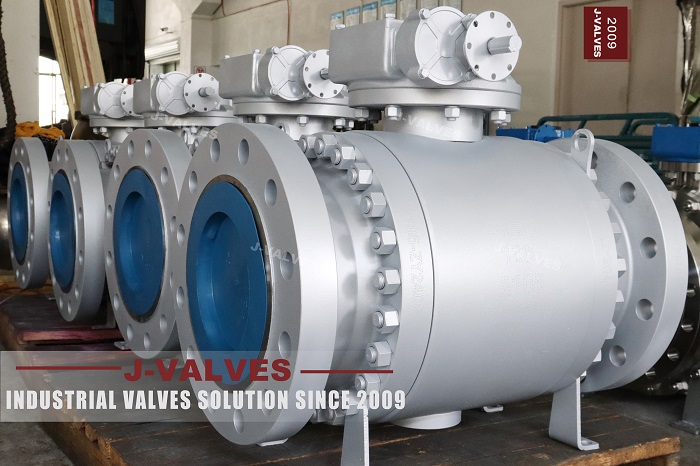
A range page for a forged trunnion valve usually gets read as a table of sizes, and the question that follows is always about material. That is the second question. The first one is how the trim comes out, because on a line valve the trim is what gets replaced, and the body style decides whether that happens in an afternoon or over a shutdown. Three piece, two piece and top entry are three different answers to the same maintenance question.
This page is about those three answers. It does not cover what the size range means, because that is a different argument about where the ends of the range stop being realistic products. It does not cover which alloy to choose either, because the alloy question starts after the body question is settled. What it covers is the space each style needs in the line, and the number of pressure joints each one puts in the flow path.
Design and Construction
A three piece body has two bolted joints, one each side of the middle section, and both are pressure boundaries. The middle section carries the ball and both seats, so releasing the studs on both ends lets the whole trim be lifted out while the two end pieces stay bolted to the pipe. That is the most complete access of the three and it is also the one that needs the most room around the valve.
A two piece body has one joint, at one end, and the end cap travels along the axis to clear the ball before the trim comes out. That needs less room than the three piece but it needs clearance specifically in the direction of the pipe, which is exactly where a spool piece or a flange that can be spread is required. A top entry body has no bolted joint in the flow path at all: the bonnet comes off the top and the ball and seats come out upwards. The comparison is therefore axial room versus cutting: the selection depends on how much removal and repair access the line can tolerate, and a split body is not automatically the easier of the two to work on.

Material Options
The body is forged rather than cast, which at the middle and upper sizes is what makes the three piece construction practical, because each section is a forging that can be made without the porosity a casting of the same wall would carry. The code is whatever the order states and the plate carries that code rather than a mill designation. Which code belongs on a given service is a separate question and is not settled by anything on this page.
The seat is PTFE as standard with reinforced PTFE, PPL or a metal seat available. The stem and the trunnion are named on the order. On a range page it is worth saying plainly that the alloy does not change the body style: a three piece body in one forging code and a top entry body in the same code are two different products with the same material list, and the choice between them is mechanical.
| Component | Standard Material | Optional Upgrade | Service Notes |
|---|---|---|---|
| Body style | three piece, two bolted joints | two piece or top entry | the decision this page is about |
| Body | forged carbon steel, code as stamped | other forging codes on order | forged at the sizes where casting is limited |
| Ball | forged steel with hard facing | stainless on order | carried on trunnions |
| Seat ring | PTFE | reinforced PTFE, PPL or metal | sets the temperature ceiling |
| Access | middle section lifted out | end cap along the axis, or trim from the top | needs room, not just a flange |
| Pressure joints in the flow path | two | one, or none for top entry | each one is a place that can weep |
| End facing | ASME B16.5 or EN 1092-1 | stated separately from the class | two systems, one rating |
| Operator | lever, gear or actuator | named on the order | pad height on the drawing |
Technical Specifications
Flanges follow ASME B16.5 or EN 1092-1 as stated, and the two are not interchangeable at the same nominal pressure, so the flange standard belongs on the order separately from the class. Face to face follows ASME B16.10 for a flanged valve of the size and class ordered, and the dimensions of a particular build are on the signed general arrangement drawing. The class range runs from 150 to 2500 and the pressure code follows API 6D clause 7.2.
The dimension that this page adds to the usual list is the clearance. A three piece body needs room on both sides and above for the middle section to be lifted; a two piece body needs axial room on the joint side; a top entry body needs headroom above the bonnet and nothing at the sides. Those three requirements are what the layout drawing has to satisfy, and they are routinely discovered after the valve has been ordered.
| Item | Value |
|---|---|
| Body style | three piece, two gasketed body joints |
| Alternative styles | two piece with axial travel, or top entry |
| Body material | forged carbon steel, code as stamped |
| Ball support | trunnion mounted |
| Seat material | PTFE as standard |
| Seat options | reinforced PTFE, PPL or metal seat |
| Size range | per the catalogue, size confirmed at order |
| Class range | 150 to 2500, pressure code per API 6D clause 7.2 |
| End connection | ASME B16.5 or EN 1092-1, stated on the order |
| Face to face | dimension on the signed GA drawing, held to ASME B16.10 |
| Design standard | ASME B16.34 and API 6D |
| Test standard | API 598 shell and seat test |
| Test pressure | shell 1.5 times and seat 1.1 times the class rating |
| Pressure joints in flow path | two on a three piece body |
| Access requirement | room on both sides and headroom above |
| Two piece access | axial clearance on the joint side |
| Top entry access | headroom above the bonnet, nothing at the sides |
| Temperature range | per the seat material and body code, stated on the order |
| Operator | lever, worm gear or actuator |
| Marking | size, class, body code, heat number |
| Documentation | EN 10204 3.1 on request |
| Weight | quoted with the drawing for the size and trim ordered |
| Range page note | the body style is the first decision, the alloy the second |
Standards and Compliance
ASME B16.34 sets the wall and the rating, API 6D sets the pipeline valve requirements including the marking and the documentation, and API 598 sets the shell and seat acceptance. All three treat the body as a pressure boundary without distinguishing between the three styles, which is correct from a testing point of view and unhelpful from a maintenance one: a three piece body has two joints to prove and a top entry body has none in the flow path.
Where the project specifies a fire safe design, the standard has to be named rather than described, because API 607, API 6FA and ISO 10497 cover different valve types and a certificate to the wrong one is refused. None of them changes the body style question either, which is the point of keeping the two decisions apart, and a buyer who settles the fire standard first will still have to answer the body question afterwards.
| Requirement | Standard | What J-VALVES Supplies |
|---|---|---|
| Pressure boundary | ASME B16.34 | minimum wall and the rating for the alloy group |
| Pipeline valve | API 6D | design, testing, marking and documentation |
| Shell and seat test | API 598 | 1.5 times the rating for the shell, 1.1 times for the seat |
| Flange pattern | ASME B16.5 or EN 1092-1 | stated separately from the class |
| Face to face | ASME B16.10 | flanged valve length for the size and class |
| Pressure code | API 6D clause 7.2 | PN and Class are two notations of one rating |
| Fire test | API 607, 6FA or ISO 10497 | named on the order, not interchangeable |
| Marking | API 6D | size, class, body code, heat number |
| Documentation | EN 10204 3.1 | issued against the heat number on request |
Manufacturing Process
The sections are forged and then machined, with the joint faces of the three piece version acting as the datum for the seat pockets so that the pockets stay square to the surfaces they seal against. A top entry body is machined from the flange faces instead, because the bonnet joint is the datum that the trim hangs from. The same shop builds both, and the machining sequence differs because the datum differs.
Assembly follows the body style. Three piece: middle section in between the end pieces over new gaskets, studs brought down in a cross pattern until the faces are parallel. Two piece: end cap onto the body over a new gasket. Top entry: trim down into the body and the bonnet closed over a new gasket. In all three the valve is cycled before it is tested, because a valve tested before bedding can pass and then weep.

Quality Control and Testing
The shell test is the same figure in all three styles, one and a half times the rating, and the seat test is one and one tenth times in both directions with the cavity open. What differs is how many places the shell test has to watch: two joints on a three piece body, one on a two piece, and none in the flow path of a top entry, where the bonnet joint is outside it but still has to be proved.
The record that matters for this page is not the test sheet but the drawing, because the drawing states which body style was built, the gasket type at each joint, the torque for each joint, and the clearance the style needs. A valve that arrives as a three piece body on a line laid out for a two piece one will pass every test and still not be installable.
| Step | What Is Checked | Standard or Acceptance |
|---|---|---|
| Forged sections | code, heat number, certificate | checked against the stamped code |
| Joint faces | flatness and finish, all faces that seal | the datum for the seat pockets |
| Seat pockets | square to their own datum | the datum differs by body style |
| Assembly | faces parallel before studs are torqued | cross pattern from the drawing |
| Shell test | wall and every bolted joint | API 598 at 1.5 times the rating |
| Seat test | no visible leakage, both directions | API 598 at 1.1 times, cavity open |
| Body style record | the drawing states which style was built | the only document that does |

Applications and Industry Service
Three piece earns its two joints where the trim is changed often and there is room around the valve: test stands, batch plants, and lines where the same valve sees several different media. Two piece earns its single joint where the valve is large and the layout can give axial room on one side: transmission and main line service. Top entry earns its higher body cost where the valve is in a place nobody wants to open a flange, such as a buried or a fully insulated line.
The wrong choices are the mirror of those. Three piece on a crowded header where the middle section cannot be lifted is a valve that has to be cut out despite its maintenance claim. Two piece where neither flange can be spread is a valve that has to be cut out as well. Top entry where the headroom is taken by a walkway is a valve nobody can open, and that is discovered the first time it needs opening.

Installation, Operation and Maintenance
Three piece goes in with room on both sides and headroom above, and the middle section is supported while it is out so its faces are not set down on anything. Two piece goes in with the joint side facing wherever the axial clearance exists, which is a decision made at the layout stage rather than at the flange. Top entry goes in with the bonnet reachable, which on an insulated line means the insulation is designed around it rather than over it.
In all three cases the gasket at each joint is new at every break and the studs go down in a cross pattern to the torque on the drawing. The difference is what a rebuild costs in time: three piece is a bench job with the trim out, two piece is a bench job with the end cap off, and top entry is a job done standing at the valve with the line still full. That last one is why top entry exists despite costing more.
How to Specify and Order
The order should state the body style explicitly rather than naming a model that implies it, because the same model name is used for more than one style in most catalogues. After the style, the line needs size, class, body code, seat material, end facing, operator and test standard, and it needs the clearance the chosen style requires, stated on the layout rather than left to the installer.
Read the plate, the certificate and the drawing against each other. The plate carries size, class, body code and heat number; the certificate carries what that heat was; the drawing carries the body style, the face to face, the flange pattern, the gasket type and the joint torque. On this product the drawing is the only document that records which of the three bodies was actually built.
FAQ
Q: Which body style should I choose?
A: Choose by how the trim will be reached, not by price. Three piece gives the most complete access and needs room on both sides and above. Two piece gives access to one side and needs axial clearance on that side. Top entry gives access from above without opening any joint in the flow path. On a crowded header the three piece claim is worthless, and on a buried line the top entry is the only one that works.
Q: Does the body style change the pressure rating?
A: No. All three styles are built to the same class and proved by the same shell and seat tests. What changes is the number of pressure joints the shell test has to watch: two on a three piece body, one on a two piece, and none in the flow path of a top entry valve, where the bonnet joint sits outside it.
Q: How much room does a three piece body need?
A: Enough to lift the middle section clear, which means room on both sides and headroom above the valve. That is a layout question and it belongs on the drawing rather than in the installer judgement. A three piece valve installed where the middle section cannot be lifted is a valve that will be cut out of the line despite being sold as maintainable.
Q: Why is a top entry valve more expensive?
A: Because the body is a single pressure vessel with a bonnet rather than three sections, and the machining is more demanding. What that buys is access without opening a flange, which on a buried or heavily insulated line saves more than the premium. Where the line is accessible and the trim is changed rarely, the premium buys nothing.
Q: Does the forging matter on a range page?
A: It matters for what can be built rather than for the choice being made here. A forged section is what makes the three piece construction practical at the middle and upper sizes, because each section can be made without the porosity a casting of the same wall would carry. Which forging code to use is a separate question.
Q: What if the line is already laid out for a different style?
A: Then the style is already decided and the order should say so explicitly, because model names are reused across styles in most catalogues. The cost of discovering this after delivery is not the valve, it is the spool piece that has to be cut and the flanges that have to be re-made to give the trim its clearance.


Hot Products


News
Ball Valves in Amine CO2 Capture: Heat Stable Salts, Rich Amine, And The Three Places The Body Thins
Rich amine at 110 C with heat stable salts is where capture plant ball valves fail. Materials, velocity limits, cavity gas and seat choice, with numbers.
Read More
Fail-Safe Ball Valve Actuators: Spring Return, Stored Air, And The Torque Nobody Checks
Spring return or stored air? The answer is a torque curve, not a datasheet box. Sizing, receiver volume, closing time and four silent failures.
Read More
Ball Valve Stem Leak: The Gland, The Backseat And The Repair That Cannot Be Done Live
A stem leak on a quarter turn valve is four different failures. What gland tightening buys you, why the backseat is usually absent, and what needs a shutdown.
Read More
Ball Valves in A Kraft Pulp Mill: Black Liquor, Green Liquor And The Cost of Choosing The Alloy by Habit
White liquor at pH 14 cracks carbon steel welds, black liquor sets solid below 100 C, green liquor dregs grind seats: alloy choice and torque in a kraft mill.
Read More