


CHINA J-VALVES Offers Various High-quality I ndustrial Ball Valves
J-VALVES, a distinguished professional ball valve manufacturer rooted in China, takes pride in its extensive product portfolio. Our offerings span a wide range, including trunnion-mounted ball valves, floating ball valves, high-temperature ball valves, high-pressure ball valves, metal-sealed ball valves, ultra-low temperature ball valves, DBB ball valves, Three-way And Four-way Ball Valve, and fully welded ball valves. Each product is a testament to our commitment to precision engineering and reliable performance. Meticulously crafted, they are designed to not only meet but exceed the most stringent industrial demands, ensuring stable operation even under extreme conditions. This enables us to provide our clients with high-value services and makes our valves widely sought-after in industries.
Product Category
Contact Us


-
J-VALVES-Q47F
-
J-VALVES
Overview of the J-VALVES 6x4 Inch 300LB WCB F236 Two Piece Reduced Bore Trunnion Ball Valve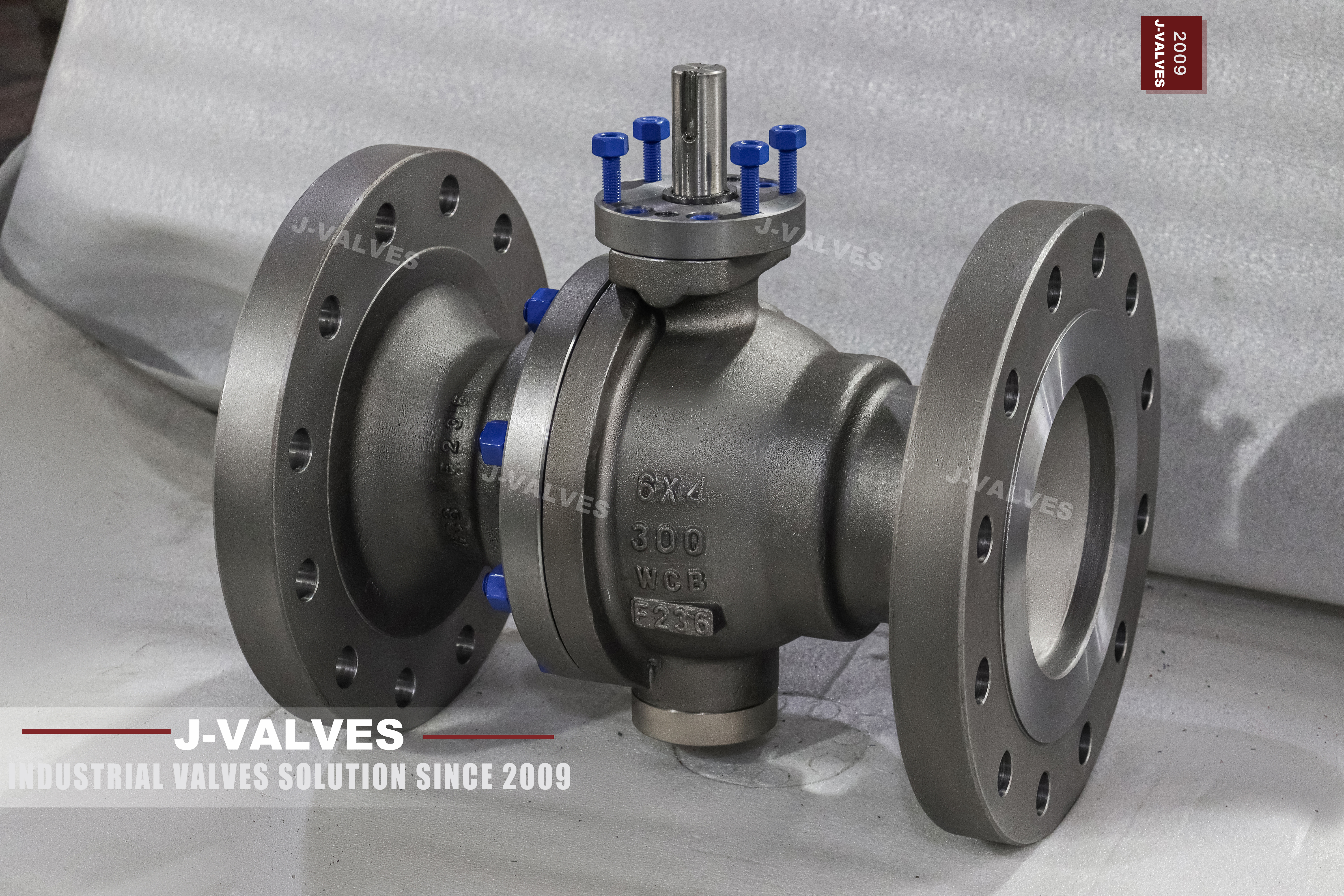
A double block and bleed valve is bought for what happens between its two seats, and that space is where this page starts. Two independent seat rings seal the line on both sides of the ball, so the cavity between them can be bled and proved empty while the line stays live. What the buyer rarely asks, and what decides the build, is where the pressure in that cavity goes when the valve is closed and the line heats up. The seats can be arranged to answer that question in three different ways.
The three arrangements are printed as single piston effect, double piston effect, and a combination of the two, and this page calls the double piston version DIB 1 and the combination DIB 2. They differ in one behaviour only: whether the body cavity relieves itself through a seat. Everything else on the valve, the body code, the bore, the flange and the gearbox, is common to all three. That is why the seat arrangement is the field most often left blank on an enquiry, and the field that decides whether the valve can be used at all.
Design and Construction
The ball is carried on an upper and a lower trunnion, so line pressure pushes the ball into the downstream seat without the stem having to hold it. Behind each seat ring sits a ring of coil springs, and those springs keep the seat against the ball when the line is empty. At pressure the medium adds to the spring load in proportion, which is why the seat holds from a few bar up to the class rating without changing anything. A floating ball would have to be turned against the full seat load at this diameter, which is why this body is trunnion mounted rather than floating.
The body is in two pieces with one bolted joint, and both seat pockets are machined in the same half. That keeps the two pockets coaxial, which matters more on a reduced bore valve than on a full bore one, because a DN100 passage through a DN150 body leaves less material around the pocket. The joint carries a gasket and a ring of studs, and it is the only pressure boundary opened in the field. A two piece body is chosen here for access to the seats, not as a cheaper three piece.
Material Options
The body is cast carbon steel and the plate carries the catalogue code rather than a standard designation, which is the string the mill certificate is written against. The ball is the same carbon steel with hard chrome plating, or stainless on request, and the stem is precipitation hardening stainless or the body alloy. None of these are upgrades in the marketing sense. Each answers a wear question, and the order has to name the one it wants, because the certificate behind the 3.1 document follows the code that was stamped and nothing else.
The seat is the part that gets chosen by the medium, and on this valve it is a soft seat carrying an F236 insert in the seat ring. That insert is a wear part: with a clean medium it lasts as long as the seat ring, and with fines it is what fails first, which is why the seat ring and not the body is the line on the spares list. A metal seat with hard facing is offered above the elastomer band and for abrasive duty, and it is a different leakage class rather than a better version of the same seat.
| Component | Standard Material | Optional Upgrade | Service Notes |
|---|---|---|---|
| Body | cast carbon steel, code as stamped | not offered in another alloy | one bolted body joint |
| Ball | same carbon steel with hard chrome | stainless 316 | load taken by the trunnion |
| Stem | precipitation hardening stainless | 316 stainless | retained by the body cover |
| Seat ring | soft seat with an F236 insert | PPL insert or metal facing | the part chosen by the medium |
| Seat springs | coil springs behind each seat | not offered | sets the low pressure seal |
| Seat arrangement | double piston effect, DIB 1 | single piston effect or combined DIB 2 | decides cavity relief |
| Bearing | self lubricating composite | not offered | takes the side load off the stem |
| Body joint | one gasketed studded joint | ring joint ends on request | new gasket at every break |
| Operator | worm gear | bevel gear, pneumatic, electric | pad height not stated on the page |
Technical Specifications
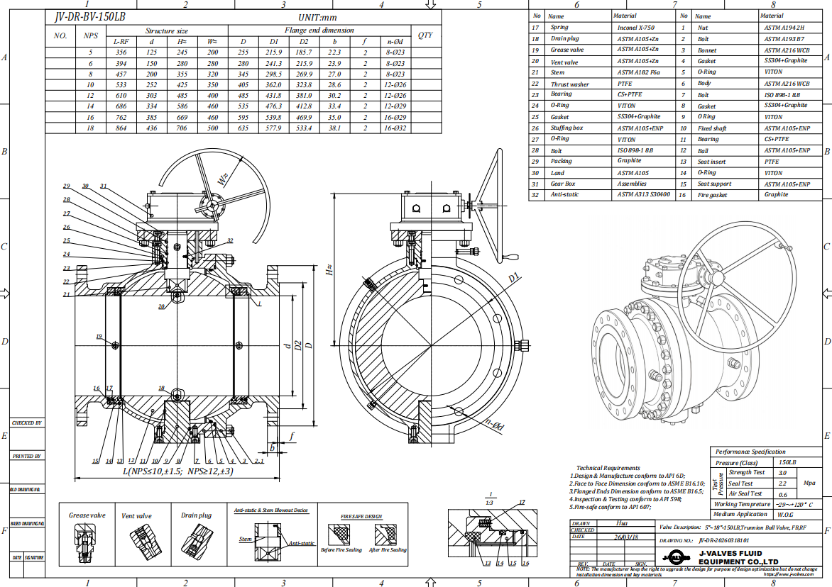
Face to face follows ASME B16.10 for a flanged valve of this size and class, and the flange is an ASME B16.5 Class 300 pattern in raised face or ring joint. Neither is printed here as a number, because the number belongs to those tables and quoting it from a page would make it look measured. What the size data sheet gives is the DN100 bore and the DN150 flange; the assembled length, the gearbox envelope and the weight of a particular build are dimensioned on the signed general arrangement drawing for the trim that was ordered.
Class 300 is PN 50 in the API 6D pressure code, and the rating is not one number: it falls with temperature, and the table that governs the fall is in ASME B16.34 for the material group the body belongs to. That matters more here than the class number does, because a valve bought for a hot line is bought at a reduced rating. The shell and seat acceptance figures come from API 598 at one and a half and one and one tenth times the rating, so the test follows the reduced rating rather than the nominal class.
| Item | Value |
|---|---|
| Nominal size | 6x4 inch (DN150 x DN100) |
| Pressure class | Class 300 (PN 50, the API 6D pressure code) |
| Body style | two piece, one gasketed body joint |
| Ball support | trunnion mounted, upper and lower shafts |
| Bore | reduced bore, DN100 through the ball |
| Body material | WCB cast carbon steel, catalogue code as stamped |
| Ball material | A105N or the body alloy with hard chrome, 316 optional |
| Stem material | 17-4PH stainless or 316 stainless |
| Seat ring | soft seat with an F236 insert |
| Seat loading | coil springs behind each seat ring |
| Seat arrangement | double piston effect, DIB 1, as standard |
| Seat options | single piston effect or combined DIB 2 on request |
| Cavity relief | not through double piston seats, external device to be ordered |
| Self relieving | yes with single piston effect or combined DIB 2 |
| End connection | raised face or ring joint flange, ASME B16.5 Class 300 |
| Face to face | dimension on the signed GA drawing, held to ASME B16.10 |
| Design standard | ASME B16.34 and API 6D, with API 608 |
| Test standard | API 598 shell and seat test |
| Test pressure | shell 1.5 times and seat 1.1 times the class rating |
| Temperature range | minus 29 to plus 425 Celsius, metal temperature |
| Fire test | API 607, 6FA or ISO 10497, named on the order |
| Anti static device | described as standard on the source page |
| Anti blow out stem | described as standard on the source page |
| Operation | worm gear or bevel gear, actuator on request |
| Marking | size, class, body code, heat number, seat arrangement |
| Documentation | EN 10204 3.1 on request |
| Weight | quoted with the drawing for the size and trim ordered |
Standards and Compliance
A marking on the plate is a claim about which documents the valve was built to, and three of them apply here. ASME B16.34 supplies the minimum wall and the pressure temperature table. API 6D is the pipeline document: design, materials, welding, testing and marking for a valve in a transmission or process line. API 608 is the quarter turn product standard, and where the two overlap it is 6D that sets the higher bar, which is why the marking on a pipeline valve names both rather than only the easier one. A certificate quoting only the quarter turn standard is worth questioning on a line order.
Two claims on that page are worth separating. Fire safety is listed as API 607, API 6FA or ISO 10497, and those three are not interchangeable: one is a test on soft seated quarter turn valves, one is written for pipeline valves to API 6D, and one is a method rather than a product standard. A certificate to the wrong one is rejected at the gate. The anti static device and the anti blow out stem are described as standard here, and both are design features that can be confirmed on the drawing rather than assumed from a feature list.
| Requirement | Standard | What J-VALVES Supplies |
|---|---|---|
| Pressure boundary | ASME B16.34 | minimum wall and the rating for the alloy group at Class 300 |
| Pipeline valve design | API 6D | design, materials, testing and marking |
| Quarter turn product | API 608 | applies, 6D is stricter where they overlap |
| Shell and seat test | API 598 | 1.5 times the rating for the shell, 1.1 times for the seat |
| Flange pattern | ASME B16.5 Class 300 | raised face or ring joint, DN150 |
| Face to face | ASME B16.10 | flanged valve length for the size and class |
| Fire test | API 607, API 6FA or ISO 10497 | named on the order, the three are not interchangeable |
| Marking | API 6D and the order | size, class, body code, heat number, seat arrangement |
| Documentation | EN 10204 3.1 | issued against the heat number on request |
Manufacturing Process
The seat pocket is the feature that decides whether this valve passes its seat test. It is bored and faced in one setup with the trunnion bore, then the seating face is lapped flat, because a soft insert will follow a face that is a few hundredths out but will not seal against one that is wavy. The springs sit in a recess behind the seat ring and are checked for free length before assembly, since a spring that has taken a set changes the low pressure behaviour of the whole valve and does not show on a shell test.
Assembly runs from the inside out. The ball goes into the body half that carries both pockets, the seats and springs follow, and the second half is drawn on over a new gasket with the studs lubricated to a stated friction and tightened in a cross pattern until the faces are parallel. The valve is then cycled and the cavity is bled and proved before the nameplate goes on, because a cavity that will not hold is a seat problem that only shows up after the paint has dried and the valve has been shipped.

Quality Control and Testing
Testing follows API 598, and on a double block and bleed valve the interesting test is the one in the middle. The shell test at one and a half times the rating proves the body and the bolted joint. The seat test in both directions at one and one tenth times proves each seat separately, with the cavity open to atmosphere and the bleed point watched. That sequence is what shows the two seats are independent, rather than one seat and one seal doing the same job twice.
Records are three documents read against each other. The nameplate states size, class, body code, heat number and seat arrangement. The mill certificate behind the 3.1 documentation states what that heat was. The test sheet states what the valve did under pressure. If the buyer wants positive material identification it is written on the order rather than assumed, and if a cavity relief device is part of the supply it is tested with the valve rather than shipped loose in a bag with the manual.
| Step | What Is Checked | Standard or Acceptance |
|---|---|---|
| Incoming castings | code, heat number, wall thickness | certificate against the stamped code |
| Seat pocket | bore, depth, face flatness | lapped after boring, checked against the drawing |
| Seat springs | free length, seat ring fit | springs rejected once they have taken a set |
| Body joint | gasket batch, stud torque | cross pattern to the drawing value |
| Shell test | no leakage through any pressure boundary | API 598 at 1.5 times the rating |
| Seat test | no visible leakage, each direction | API 598 at 1.1 times the rating |
| Cavity check | bleed point holds, cavity proves empty | both seats closed, before marking |

Applications and Industry Service
This valve belongs where a line has to be proved empty between two seats: a manifold branch, a meter run, a tank farm header, a loading arm isolation point. In those places the bleed is used on every shift and the valve is either fully open or locked closed. The trunnion and the spring loaded seats are what make it usable at this size, because the seat load at six inch is more than a lever should carry by hand, and the springs keep the seal while the line is being blown down.
It is the wrong valve in three situations. A line that heats up while shut, with both seats closed and no relief device, will push the cavity pressure up until something yields, and double piston seats will not let it out. A medium carrying solids will damage a soft insert faster than a metal seat would. And a service that cycles daily turns the seat insert and the packing into consumables, which is a maintenance plan rather than a valve choice.

Installation, Operation and Maintenance
Install with the stem vertical or horizontal and the gearbox reachable from the walkway. Leave the bleed point accessible, because on a double block and bleed valve the bleed is the working part rather than a commissioning extra. If a cavity relief device is fitted, its outlet has to go somewhere safe and it must not be plugged to stop a weep: a plugged relief turns the cavity into a pressure vessel with a gasket for a lid. Bring the mating flanges parallel before the studs are tightened, and use a new gasket at the body joint on every break.
Maintenance splits into two jobs. Packing can be renewed from the top with the line live, because the stem is retained by the body cover. Seat work needs the body joint open, which means a new gasket, clean faces and the torque pattern from the drawing. The springs and the seat inserts are the parts to inspect: a spring that has lost free length shows as a valve that weeps at low pressure and holds at high pressure, and that symptom is usually misread as a damaged seat.
How to Specify and Order
The order line needs more than size, class and body code. Bore, seat arrangement, cavity relief, seat compound, end facing, operator and test standard all change the build, and two of them are easy to leave out: whether the seats are single or double piston effect, and whether a cavity relief device is part of the supply. Both have a default. On a double block and bleed valve the default may not be the one the line needs, and neither of them shows up in the price.
Three documents should be read against each other before acceptance: the nameplate, the mill certificate and the drawing. On this valve the nameplate also carries the seat arrangement, and on a combined DIB 2 valve the body carries a preferred direction marking, because the self relief works one way round only. That arrow is the difference between a valve that relieves and a valve that does not, and it is set at the factory rather than in the field.
FAQ
Q: What is the difference between DIB 1 and DIB 2 seats?
A: DIB 1 is a double piston effect seat: pressure from either side pushes the seat onto the ball, so the valve seals both ways and gives a double barrier, but the body cavity cannot relieve itself. DIB 2 combines a single and a double piston seat, so the valve still gives a double barrier while the cavity relieves, but only in one direction, which is why the body carries a preferred direction marking.
Q: If the seats are double piston effect, where does the cavity pressure go?
A: It does not go anywhere on its own. With double piston seats both seats are pushed onto the ball by pressure from either side, so a trapped and warming cavity keeps its pressure until something yields. The order has to provide a path: either a body cavity relief device, or single piston seats, or a combined arrangement, and whichever it is has to be on the drawing rather than decided at commissioning.
Q: Does a double block and bleed valve need two valves?
A: No. The two seats of one trunnion valve give the two barriers, and the bleed between them proves the cavity is empty. Two valves in series do the same job with more joints, more space and one more thing to operate. What a single valve cannot do is isolate and bleed at the same time in both directions without the right seat arrangement, which is the point of the DIB discussion.
Q: Why is F236 listed with the seat and not with the body?
A: Because it is a compound used for the seat insert, not a body material. The body is cast carbon steel with its own catalogue code stamped on the plate; the insert is an elastomer whose hardness, compression set and temperature band come from the compound callout on the order. Reading the two as one string is how a buyer ends up asking for a steel grade that does not exist.
Q: What is the bore of a 6x4 valve?
A: The body takes a six inch flange and the passage through the ball is four inch, so the bore is DN100 in a DN150 body. That is the reduced bore value in the API 6D table, not a smaller hole drilled in a six inch valve. It changes the pressure drop and the torque, and it does not change the shell test, which is done at the class rating for the whole valve.
Q: Is this the same valve as the other 6x4 listings on the site?
A: The site carries several URLs for a six by four inch Class 300 trunnion valve in cast carbon steel, some of them with the F236 seat and slightly different titles. They describe one valve. Pages for the same valve compete for the same query and split their own link equity, so one URL should be kept as the indexed page and the others redirected to it.


Hot Products


News
Ball Valves in A Kraft Pulp Mill: Black Liquor, Green Liquor And The Cost of Choosing The Alloy by Habit
White liquor at pH 14 cracks carbon steel welds, black liquor sets solid below 100 C, green liquor dregs grind seats: alloy choice and torque in a kraft mill.
Read More
Slug Flow And Ball Valves: What Actually Arrives At The Seat
A slug is liquid mass with momentum, not a pressure spike. What changes at the seat, in the cavity and at the actuator when liquid reaches a ball valve.
Read More
Ball Valves in Direct Lithium Extraction: PH 1 Eluate, Gypsum Scale And 438,000 Cycles in Twenty-Five Years
Direct lithium extraction swings valves from pH 1 eluate to pH 12 caustic, 48 column switches a day and gypsum scale. Materials, seats and torque.
Read More
Ball Valves in Geothermal Brine: Silica Scale, Chloride Cracking And The Cooling Trap
Why geothermal brine destroys ball valves: retrograde silica scale, calcite at the flash point, chloride cracking above 60 C and the 250 C seat limit.
Read More