


CHINA J-VALVES Offers Various High-quality I ndustrial Ball Valves
J-VALVES, a distinguished professional ball valve manufacturer rooted in China, takes pride in its extensive product portfolio. Our offerings span a wide range, including trunnion-mounted ball valves, floating ball valves, high-temperature ball valves, high-pressure ball valves, metal-sealed ball valves, ultra-low temperature ball valves, DBB ball valves, Three-way And Four-way Ball Valve, and fully welded ball valves. Each product is a testament to our commitment to precision engineering and reliable performance. Meticulously crafted, they are designed to not only meet but exceed the most stringent industrial demands, ensuring stable operation even under extreme conditions. This enables us to provide our clients with high-value services and makes our valves widely sought-after in industries.
Product Category
Contact Us


-
J-VALVES-Q347F
-
J-VALVES
Overview of the J-VALVES 14 Inch 300LB WCB Two Piece Flange Trunnion Mounted Ball Valve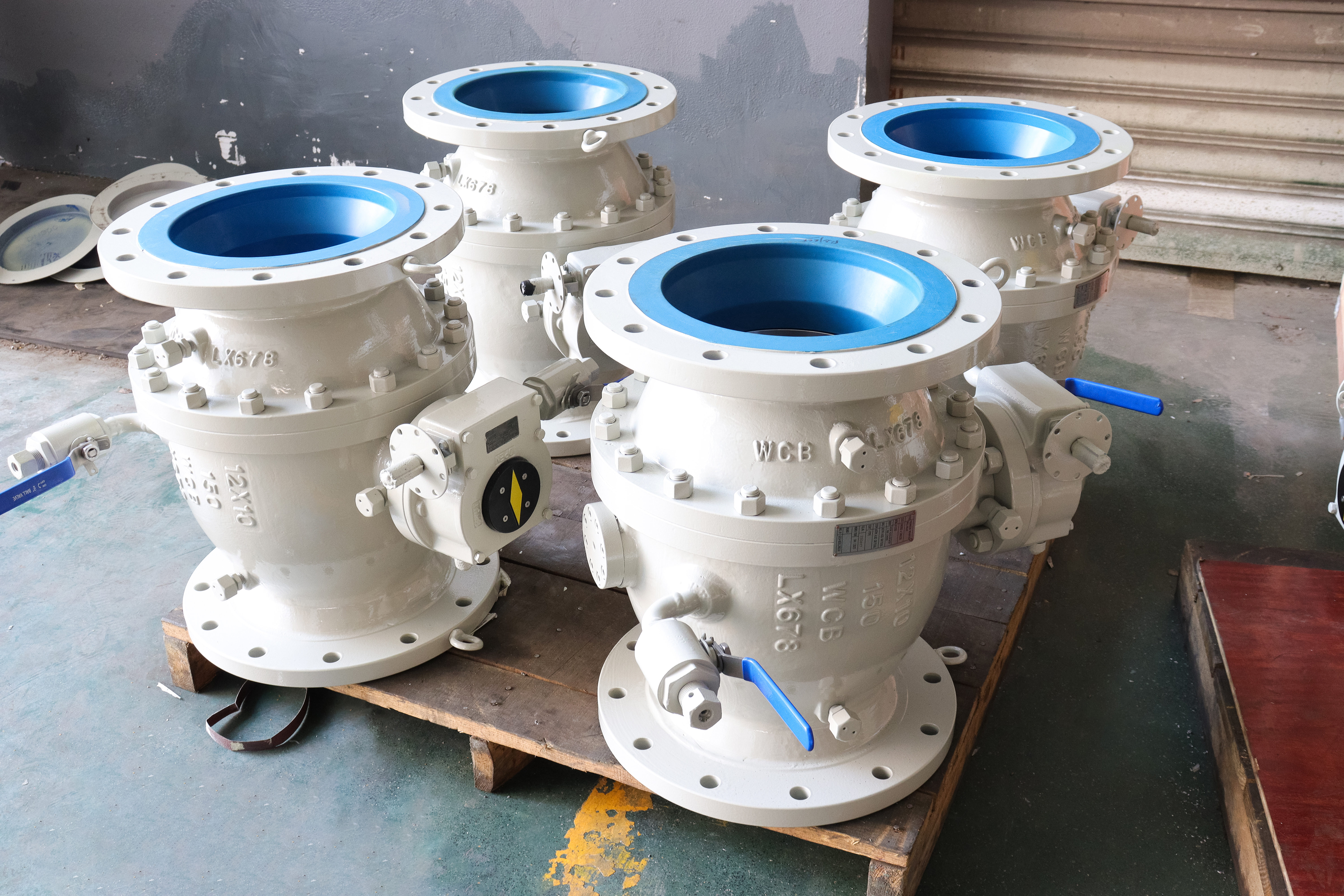
There is a size at which a valve stops being a fitting and becomes a piece of equipment, and for a flanged trunnion valve that point arrives somewhere around the lower end of the fourteen to sixteen inch range. Below it, the valve hangs on its flanges and nobody thinks about it. Above it, the valve is heavier than the pipe it interrupts, and the pipe was never designed to carry it. That change does not appear on any data sheet, which is why it catches projects out.
What happens when it is ignored is slow and easy to misread. The flange studs take the weight as a bending moment, the gaskets see a load that varies along the ring rather than evenly, and the joint passes the shell test because the shell test is short. Then the line runs, cycles thermally, and the joint that was even becomes uneven. This page is about the support, the lift and the alignment, which are the three things that decide whether a fourteen inch valve of this type stays tight.
Design and Construction
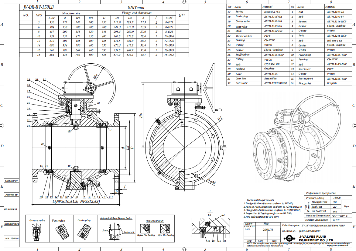
Two pieces, one bolted joint. The joint is on the upstream side of the ball, so the end cap comes off towards the pipe and the ball and both seats come out with it. That is the whole maintenance argument for this body style, and it comes with a condition that is easy to miss at this size: the end cap has to travel along the axis before it clears the ball, so the pipe on that side has to be able to give that much room, either by a spool piece or by a flange that can be spread.
The ball is carried on trunnions, which is not a refinement at DN350 but a necessity. A floating ball of this diameter would transfer the whole line force into the downstream seat, and no hand gear could turn it back. The trunnions take that force into the body, and the seats only have to seal. That is also why the operator here is a worm gear rather than a lever: the gear multiplies a small hand input into the torque the stem actually needs.
Material Options
The body code is WCB, a cast carbon steel, and at fourteen inch casting is the practical route because a forging of this diameter and wall would be a special order rather than a catalogue item. The trade is that a casting has to be inspected for porosity in a way a forging does not, and the parts that matter are the seat pockets and the joint face rather than the general wall. The code on the plate is what the certificate is written against.
The seat is PTFE as standard with reinforced PTFE or PPL listed for higher temperature, and the choice sets the ceiling of the valve rather than the class. The stem and the trunnion are named on the order. Where the service is cold enough to need a low temperature steel, the body code changes and the whole valve is ordered against that code; it is not an upgrade applied to this one.
| Component | Standard Material | Optional Upgrade | Service Notes |
|---|---|---|---|
| Body | WCB cast carbon steel, code as stamped | low temperature or stainless casting on order | cast at this diameter rather than forged |
| Ball | carbon steel with hard facing | stainless on order | carried on trunnions |
| Trunnion | surface hardened, or 17-4PH | named on the order | takes the full line force |
| Stem | 17-4PH or equivalent | named on the order | driven by the worm gear |
| Seat ring | PTFE | reinforced PTFE or PPL | sets the temperature ceiling |
| Body joint | one gasketed studded joint | not offered as a welded body | end cap travels axially |
| End facing | raised face or ring joint to B16.5 | chosen at order | groove is cut, not added |
| Operator | worm gear | lever not practical at this size | lift by the body, not the gear |
Technical Specifications
The numbers on this valve come from two places and only two. The flange drilling, and whether the face is raised or ring joint, come from the ASME B16.5 Class 300 row at fourteen inch, so the pattern is the one every supplier works to. The face to face comes from ASME B16.10 for a flanged valve of this size, and the built length is dimensioned on the signed general arrangement drawing rather than printed here. What no table supplies is the mass, and on this valve the mass is what the support is designed from. Class 300 is PN 50 in the API 6D code, which converts the rating and says nothing about the drilling.
The number that is not on the data sheet and matters most on this valve is its mass, and it is deliberately not printed here because it changes with the operator, the trim and the end facing. It is quoted with the drawing, and it is the figure the structural engineer needs in order to design the support. A buyer who orders the valve without that figure usually ends up with the support designed after the valve arrives, which is the wrong order.
| Item | Value |
|---|---|
| Nominal size | 14 inch (DN350) |
| Pressure class | Class 300 (PN 50, the API 6D pressure code) |
| Body style | two piece, one gasketed body joint |
| Ball support | trunnion mounted |
| Bore | full bore |
| Body material | WCB cast carbon steel, code as stamped |
| Ball material | carbon steel with hard facing |
| Trunnion material | surface hardened, or 17-4PH on order |
| Stem material | 17-4PH or equivalent, stated on the order |
| Seat material | PTFE as standard |
| Seat options | reinforced PTFE or PPL |
| End connection | raised face or ring joint flange, ASME B16.5 Class 300 |
| Face to face | dimension on the signed GA drawing, held to ASME B16.10 |
| Design standard | ASME B16.34 and API 6D |
| Test standard | API 598 shell and seat test |
| Test pressure | shell 1.5 times and seat 1.1 times the class rating |
| Temperature range | minus 29 to plus 425 Celsius, metal temperature |
| Temperature ceiling | set by the seat material, not by the body code |
| Installation requirement | body supported, flange studs not structural |
| Lifting points | on the body, never the gear or the stem |
| End cap travel | axial clearance needed on the joint side |
| Operation | worm gear |
| Marking | size, class, body code, heat number |
| Documentation | EN 10204 3.1 on request |
| Mass | quoted with the drawing, needed for the support design |
Standards and Compliance
The pressure boundary is governed by ASME B16.34, which supplies the minimum wall and the rating at temperature, and the pipeline requirements come from API 6D. At fourteen inch and Class 300 the two agree on the wall and differ in scope: 6D adds the functional tests, the marking and the documentation that a transmission line buyer will ask for. The shell and seat acceptance figures come from API 598, at one and a half times and one and one tenth times the rating.
Nothing in those three documents mentions how the valve is held up, which is the gap this page exists to fill. Support and lifting belong to the piping design and to the installation method statement, not to the valve standard, so a valve that meets every clause of 6D can still be installed in a way that destroys its joints. The standard proves the valve; the installation proves the joint.
| Requirement | Standard | What J-VALVES Supplies |
|---|---|---|
| Pressure boundary | ASME B16.34 | minimum wall and the Class 300 rating at temperature |
| Pipeline valve | API 6D | design, testing, marking and documentation |
| Shell and seat test | API 598 | 1.5 times the rating for the shell, 1.1 times for the seat |
| Flange pattern | ASME B16.5 Class 300 | fourteen inch, raised face or ring joint |
| Face to face | ASME B16.10 | flanged valve length for the size and class |
| Pressure code | API 6D clause 7.2 | Class 300 is written PN 50 |
| Marking | API 6D | size, class, body code, heat number |
| Documentation | EN 10204 3.1 | issued against the heat number on request |
| Support and lifting | piping design, not a valve standard | the gap this page exists to fill |
Manufacturing Process
The body is cast, cleaned and inspected before any machining, and the first machining operation establishes the joint face and the flange faces as one datum set. The seat pocket is then cut from the joint face so that the pocket is square to the surface it seals against, and the bore is finished from the same setup where the machine allows it. On a casting this size the wall thickness is checked before machining so that a thin section is found while it can still be scrapped rather than after it has absorbed the machining time.
Assembly is the end cap onto the body over a new gasket, the ball and seats already in place, with the studs brought down in a cross pattern until the faces are parallel. The gear operator is fitted and the valve is cycled to settle the seats before it is tested, because a valve tested before it has been cycled can pass and then weep on its first operation. The lifting points on the body are used for that operation and for nothing else.

Quality Control and Testing
The shell test is done at one and a half times the rating with the valve closed and the body joint under observation, and the seat test follows in both directions at one and one tenth times with the cavity open. On a valve of this size the test stand has to hold the body the way the line will, which means supported, because a body that is only held by its flanges during the test is being tested in a condition it will never see again.
Casting records and the test sheet are read together. The certificate states the heat and what it was, the plate carries size, class, body code and heat number, and the test sheet states what the valve did. Where the project asks for radiographic examination of the casting or for positive material identification, both are written on the order, and both are reported against the heat rather than against the individual valve.
| Step | What Is Checked | Standard or Acceptance |
|---|---|---|
| Casting | wall thickness before machining, surface | a thin section is found before it is cut |
| Joint face and flange | flatness and finish | one datum set for both |
| Seat pocket | square to the joint face | cut from the joint face |
| Assembly | faces parallel before studs are torqued | end cap finds its own position |
| Shell test | body wall and the joint, valve supported | API 598 at 1.5 times the rating |
| Seat test | no visible leakage, both directions | API 598 at 1.1 times, cavity open |
| Gear and cycle | travel, stops, operating torque | cycled before testing |
| Marking and mass | plate data and mass on the drawing | mass needed for the support design |

Applications and Industry Service
This is a line valve at a size where the line is a main rather than a branch: transmission, pump station suction and discharge, tank farm headers, and the isolation points either side of a metering run. The medium is normally clean and the duty is isolation rather than control, so the valve sits at one end of its travel for months. In those places the thing that eventually needs attention is the seat or the gear, not the body.
Two situations point away from this valve. Where the line has to be pigged, check the bore against the pig rather than against the nominal size, because a full bore valve and a reduced bore valve of the same size are different products. And where the valve has to be rebuilt where it stands without spreading a flange, the two piece body cannot give the end cap its axial travel; a top entry body reaches the same trim from above.

Installation, Operation and Maintenance
The valve is supported under the body, on a bracket or a stand that carries its mass and lets the pipe carry only its own. The flange studs are then free to do the job they were designed for, which is to compress the gasket evenly, and the joint does not have to resist a bending moment that changes with every thermal cycle. The support is designed from the mass quoted with the drawing, and it is installed before the flanges are torqued, not after.
Lifting is by the body, never by the gear operator or the stem, and never by a sling through the bore. The flanges are brought parallel with the pipe flanges before any stud is tightened, using the support to take the weight while the gap is closed, because a fourteen inch raised face cannot pull itself square. After the first thermal cycle the studs are checked again, which is a torque check rather than a re-torque.
How to Specify and Order
The order line needs size, class, body style, body code, bore, seat material, end facing, operator and test standard. On a valve this size it needs two more that are easy to forget: the mass, because the support is designed from it, and the face to face, because the spool piece that gives the end cap its axial travel is cut to it. Both are quoted with the drawing rather than assumed from the tables.
Acceptance reads three documents in a fixed order. The drawing comes first, because it carries the length, the flange pattern, the mass and the joint torque, and those are the numbers that have to match the pipe in the ground. The nameplate is checked against the drawing next: size, class, body code and heat number. The certificate is checked last and against the heat number on the plate, which is what turns a code into a traceable casting. On a valve this size the drawing is also the document that tells the rigger where it may be lifted.
FAQ
Q: Why does a fourteen inch valve need a support if a six inch one does not?
A: Because the mass of the valve grows with the cube of the size while the pipe wall grows more slowly, so at some diameter the valve becomes the heavier of the two things at the joint. Below that point the pipe can carry it without anyone noticing. Above it, the flange studs and gaskets are carrying a bending moment they were never sized for, and the joint fails slowly rather than at the shell test.
Q: What does the support actually attach to?
A: A bracket or stand under the body, sized for the mass quoted with the drawing and for the movement the line is expected to make. It attaches to the valve body or to the pipe immediately beside it, and it is set before the flange studs are torqued so that the weight is taken off the joint while the gap is closed. The support belongs to the piping design, not to the valve standard, which is why no valve certificate mentions it.
Q: Can I lift the valve by the gear operator?
A: No. The gear, the stem and the mounting pad are sized for turning torque, not for the mass of the body, and a sling around the gear will bend the stem or crack the pad before it lifts anything. Lift by the body, using the points provided, and never pass a sling through the bore where it can damage a seat face on the way through.
Q: How much axial room does the end cap need?
A: Enough for the cap to clear the ball on the joint side, which is a dimension on the drawing rather than a rule of thumb. In practice that means the spool piece on that side is cut to suit, or the flange there can be spread. Where neither is possible the valve cannot be rebuilt in place, and a top entry body is the answer rather than a bigger access hatch.
Q: Is a worm gear necessary at this size?
A: Yes in practice. The torque needed to turn a fourteen inch trunnion ball against its seats is far beyond what a lever can give a hand, and the gear is what makes the valve operable by one person. It also holds the ball in position against the seat load, which a lever does through friction alone. The gear adds mass and that mass is part of what the support has to carry.
Q: What flange pattern will the valve have?
A: ASME B16.5 Class 300 at fourteen inch, in raised face or ring joint as ordered. The pattern is fixed by the standard for this size, so the choice left to the buyer is the facing rather than the drilling, and the facing has to be decided before the flange is machined because a ring groove cannot be cut in the field.


Hot Products


News
Ball Valves in Amine CO2 Capture: Heat Stable Salts, Rich Amine, And The Three Places The Body Thins
Rich amine at 110 C with heat stable salts is where capture plant ball valves fail. Materials, velocity limits, cavity gas and seat choice, with numbers.
Read More
Fail-Safe Ball Valve Actuators: Spring Return, Stored Air, And The Torque Nobody Checks
Spring return or stored air? The answer is a torque curve, not a datasheet box. Sizing, receiver volume, closing time and four silent failures.
Read More
Ball Valve Stem Leak: The Gland, The Backseat And The Repair That Cannot Be Done Live
A stem leak on a quarter turn valve is four different failures. What gland tightening buys you, why the backseat is usually absent, and what needs a shutdown.
Read More
Ball Valves in A Kraft Pulp Mill: Black Liquor, Green Liquor And The Cost of Choosing The Alloy by Habit
White liquor at pH 14 cracks carbon steel welds, black liquor sets solid below 100 C, green liquor dregs grind seats: alloy choice and torque in a kraft mill.
Read More