


CHINA J-VALVES Offers Various High-quality I ndustrial Ball Valves
J-VALVES, a distinguished professional ball valve manufacturer rooted in China, takes pride in its extensive product portfolio. Our offerings span a wide range, including trunnion-mounted ball valves, floating ball valves, high-temperature ball valves, high-pressure ball valves, metal-sealed ball valves, ultra-low temperature ball valves, DBB ball valves, Three-way And Four-way Ball Valve, and fully welded ball valves. Each product is a testament to our commitment to precision engineering and reliable performance. Meticulously crafted, they are designed to not only meet but exceed the most stringent industrial demands, ensuring stable operation even under extreme conditions. This enables us to provide our clients with high-value services and makes our valves widely sought-after in industries.
Product Category
Contact Us


-
J-VALVES-Q347F
-
J-VALVES
Overview of the J-VALVES 14 Inch 300LB WCB Two Piece Flange Carbon Steel Trunnion Mounted Ball Valve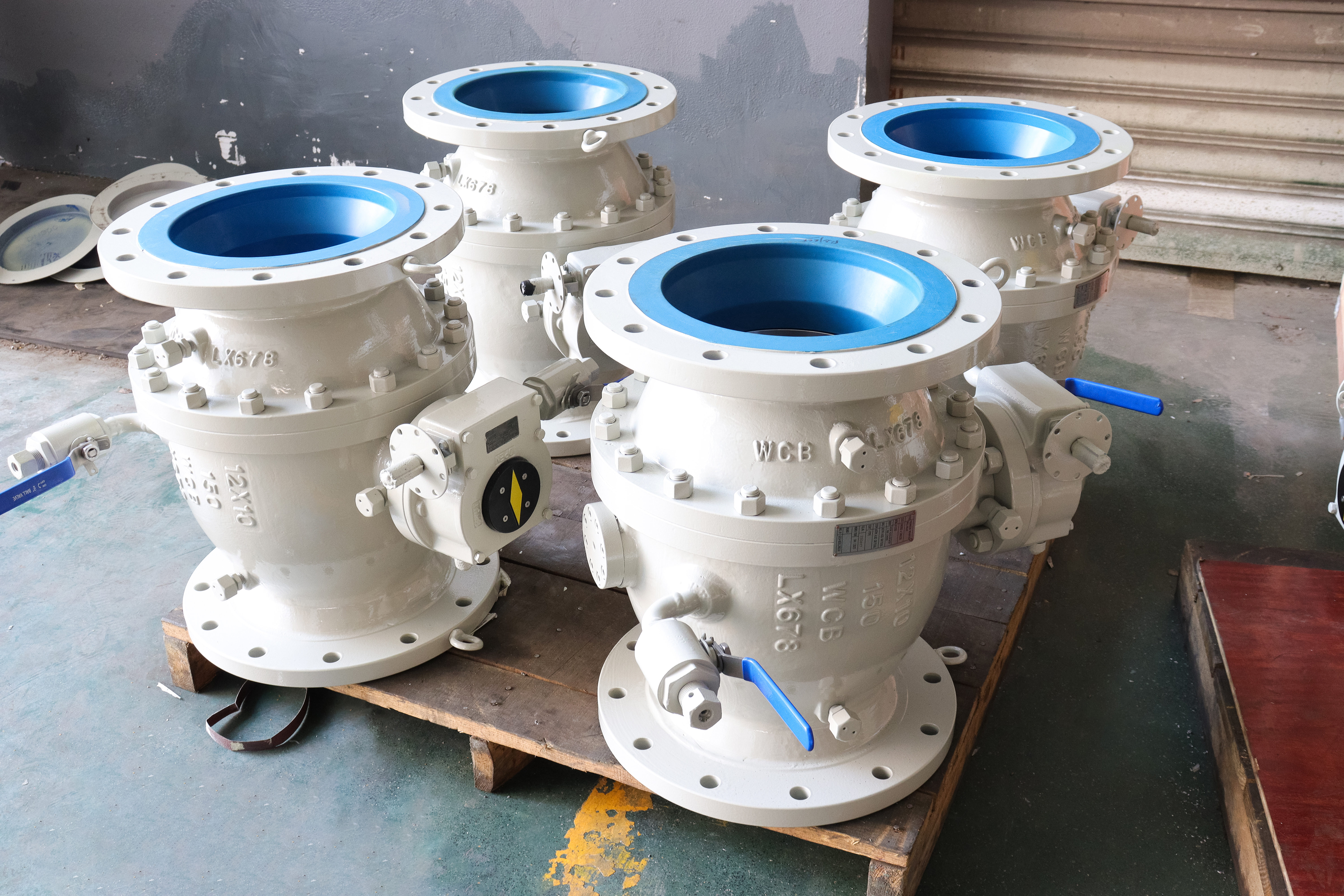
Fourteen inch is the size where the words large diameter start being used, and that is exactly when a buyer stops reading the flange standard and starts assuming. ASME B16.5 runs from half inch to twenty four inch; ASME B16.47 takes over above that. A fourteen inch flange is therefore a B16.5 part, with a B16.5 bolt circle, B16.5 stud sizes and a B16.5 gasket dimension, and none of that changes because the valve is big enough to need a gearbox.
The mistake is easy to make and expensive to fix. A gasket bought against the large flange tables will not fit the groove or the raised face, a stud set bought the same way will be the wrong diameter or the wrong length, and the error usually surfaces when the valve is on the line and the joint will not close. This page is about that boundary and about what the joint needs at DN350.
Design and Construction
The ball is carried on an upper and a lower trunnion in bearing blocks, so the side load from line pressure goes into the bearings rather than into the seats. At fourteen inch that is not a refinement, it is what makes the valve operable by hand through a gearbox: a floating ball of this size would press onto the seat with a force no operator could break away from without a bar on the lever.
The body is two pieces with one bolted joint at the end cover. The cover is the largest single part to handle during maintenance, and it comes off towards the pipe, which means the line has to be supported on that side before the studs are slackened. The trunnion blocks stay with the main body, so the ball comes out with the cover rather than staying inside.
Material Options
The body is cast carbon steel, and the nameplate carries the casting code rather than a standard designation. At this size the casting is a significant piece of work: wall thickness is generous, but the seat pocket and the flange transition are where a shrinkage cavity would show, and the code on the plate is what the mill certificate and the 3.1 documentation are written against.
Trim on a fourteen inch valve is a cost and handling decision as much as a metallurgical one. The ball is a large part with hard chrome plating, and at this diameter the plating is what the seat runs against, so its finish matters more than the base grade underneath. Seats are PTFE, reinforced PTFE, PPL or nylon in rings that are large parts in their own right; a metal seat is available but it changes the leakage class. The stem is precipitation hardening stainless. Each combination moves the temperature ceiling as well as the price.
| Component | Standard Material | Optional Upgrade | Service Notes |
|---|---|---|---|
| Body and end cover | cast carbon steel, code as stamped | the same casting grade | one bolted cover joint |
| Ball | carbon steel with hard chrome | stainless grade | large part, trunnion carried |
| Stem | precipitation hardening stainless | stainless grade | gearbox mounted |
| Seat | PTFE, reinforced PTFE, PPL or nylon | metal seat with hard facing | large rings, compound choice is a cost line |
| Packing | flexible graphite | PTFE on request | gland adjustable |
| Bearings | stainless with a self lubricating liner | not offered | takes the side load at DN350 |
| Ends | raised face to ASME B16.5 | ring joint facing | B16.5 covers this size |
| Gasket | per ASME B16.5 for the size and facing | not per B16.47 | one time part |
| Operator | worm gear | bevel gear or actuator | no pad stated on the page |
Technical Specifications
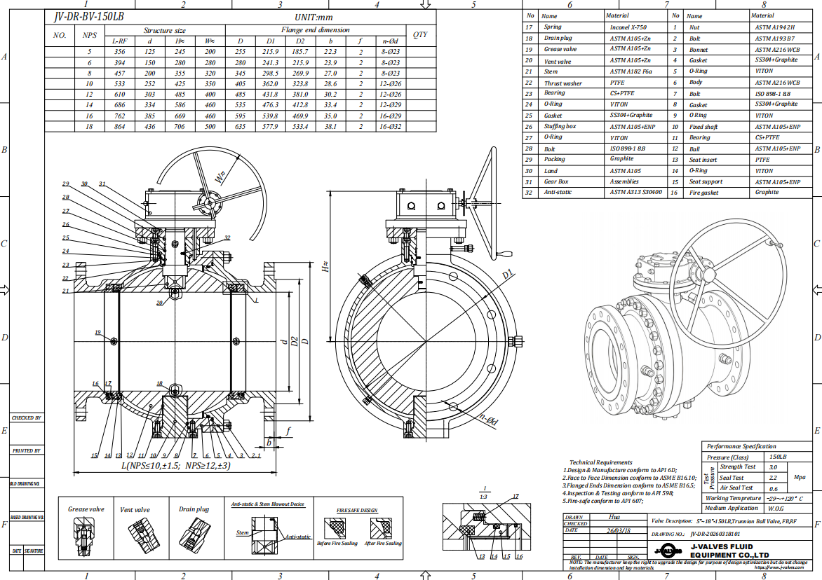
The flange is a fourteen inch Class 300 pattern to ASME B16.5, raised face standard and ring joint available. That is the same table a six inch valve uses, which is the point: the bolt count and stud size come from the row for this size, and the gasket dimensions come from the same standard. Face to face follows ASME B16.10 for the size and class. Neither number is printed here, because both belong to tables and printing them would make them look measured.
What the drawing adds is the assembled height with the gearbox and the weight of the cover, both of which matter for handling rather than for the process. A fourteen inch valve is lifted with equipment, not by hand, and the lifting points and the cover weight belong on the drawing that goes to site. The bore and the seat ring dimensions come from the size data sheet.
| Item | Value |
|---|---|
| Nominal size | 14 inch (DN350) |
| Pressure class | Class 300 (PN 50, the API 6D pressure code) |
| Body style | two piece, one bolted cover joint |
| Ball support | trunnion, upper and lower shafts in bearing blocks |
| Bore | full bore as listed for this size |
| Body material | cast carbon steel, catalogue code as stamped |
| Ball material | carbon steel with hard chrome, stainless grade optional |
| Stem | precipitation hardening stainless or a stainless grade |
| Seat | PTFE, reinforced PTFE, PPL or nylon; metal seat available |
| Packing | flexible graphite |
| Bearings | stainless with a self lubricating liner |
| End connection | raised face or ring joint, ASME B16.5 Class 300 |
| Flange standard scope | ASME B16.5 runs to twenty four inch; B16.47 starts above it |
| Gasket | dimensioned per ASME B16.5 for this size and facing |
| Face to face | dimension on the signed GA drawing, held to ASME B16.10 |
| Design standard | ASME B16.34 and API 6D, with API 608 |
| Test standard | API 598 shell and seat test, API 6D |
| Test pressure | shell 1.5 times and seat 1.1 times the class rating |
| Temperature range | minus 29 to plus 425 Celsius, metal temperature |
| Temperature limit | set by the seat compound where a soft seat is fitted |
| Operation | worm gear; bevel gear or actuator on request |
| Lifting | lifting points and cover weight shown on the drawing |
| Fire test | not claimed on this page, API 607 or 6FA to be specified |
| Anti static device | not described on this page |
| Marking | size, class, body code, heat number |
| Documentation | EN 10204 3.1 on request |
| Weight | quoted with the drawing for the size and trim ordered |
Standards and Compliance
ASME B16.34 fixes the minimum wall for the size and class and publishes the rating for the casting group. API 6D governs the pipeline valve requirements: design, materials, testing, marking. API 608 applies as the quarter turn product standard. API 598 supplies the shell and seat acceptance numbers, and API 6D adds its own requirements on top for a valve marked to it, which is why a 6D valve carries a 6D marking rather than a 608 one.
The flange standard is the fourth document and the one this page is built around. ASME B16.5 covers sizes up to twenty four inch, so a fourteen inch valve is inside it; ASME B16.47 covers the sizes above. A purchase order that names B16.47 for a fourteen inch valve is asking for a flange that does not exist in that standard, and a supplier who accepts it will either query it or, worse, ship something that looks right and does not fit.
| Requirement | Standard | What J-VALVES Supplies |
|---|---|---|
| Pressure boundary | ASME B16.34 | minimum wall and rating for the casting group at Class 300 |
| Pipeline valve design | API 6D | design, materials, testing, marking |
| Quarter turn product | API 608 | applies as the product standard |
| Shell and seat test | API 598 | 1.5 times the rating for the shell, 1.1 times for the seat |
| Flange pattern | ASME B16.5 Class 300 | covers sizes to twenty four inch, so this size is inside it |
| Large flange standard | ASME B16.47 | begins above twenty four inch, not applicable here |
| Face to face | ASME B16.10 | flanged valve length for the size and class |
| Documentation | EN 10204 3.1 | issued against the heat number on request |
Manufacturing Process
The casting is cleaned, inspected and then machined in setups that keep the bore, the seat pockets and both flange faces related to each other. At DN350 the flange face is a large surface, and its squareness to the bore is what decides whether the gasket loads evenly. A face that is out of square by a small amount over that diameter produces a joint that tightens on one side and leaks on the other, whatever the torque.
Assembly is a handling exercise as much as a technical one. The ball and the cover are heavy, the cover joint has a large gasket and a long stud circle, and the studs are drawn down in a cross pattern in several passes rather than in one. The valve is cycled with the gearbox fitted, because the gearbox is what the site will use and the torque has to be proved through it.

Quality Control and Testing
Testing follows API 598: shell at one and a half times the Class 300 rating, seat at one and one tenth times in both directions. At this size the shell test also proves the cover joint, which is the only gasketed pressure boundary on a two piece body, so a joint that is going to weep usually weeps here rather than in service, where the same leak costs a shutdown instead of a re-torque.
Dimensional checks on the flange are the ones that catch the B16.5 question. Bolt circle, bolt hole diameter, number of holes, raised face height and ring groove profile are all measured against the standard rather than against a drawing, because a drawing can be wrong in the same way the order was. Casting soundness around the seat pocket is checked before machining, since that is where a repair would be impossible.
| Step | What Is Checked | Standard or Acceptance |
|---|---|---|
| Incoming castings | wall thickness, seat pocket soundness, heat number | certificate against the stamped code |
| Flange machining | bolt circle, hole count, facing height or groove | measured against ASME B16.5, not the drawing |
| Body machining | seat pocket depth and squareness to the flange face | in process gauging |
| Cover joint | gasket batch, stud grade, torque passes | recorded per valve |
| Shell test | no leakage at body or cover joint | API 598 at 1.5 times the rating |
| Seat test | no visible leakage, both directions | API 598 at 1.1 times the rating |
| Handling data | lifting points and cover weight on the drawing | checked before packing |

Applications and Industry Service
This valve belongs on a fourteen inch line where the class is three hundred and the duty is isolation: a transmission branch, a plant header, a tank farm line, or a pump header where the valve is open for a season and shut for a maintenance window. The gearbox is there because of the size, and the trunnion is there because a floating ball would be unbreakable by hand at this diameter, whatever the class says.
It is the wrong valve where the line is pigged and the bore is reduced, where the medium attacks carbon steel, or where the flange has already been drilled to a standard nobody checked. That last case is common on brownfield work, where the existing flanges may be old ANSI drillings that differ from the current table in the number of holes, and the mismatch is only found when the studs go in.

Installation, Operation and Maintenance
Support the pipe on both sides before the studs are slackened or tightened. A valve of this size is stiff enough to be used as a pipe support by accident, and the joint will take the load until it leaks. Bring the faces parallel with a gap gauge, fit the gasket dry unless the drawing says otherwise, and torque in a cross pattern in at least three passes.
The gearbox needs its own attention: the oil level, the limit setting and the handwheel effort are checked at commissioning, and the gearbox is not a lifting point. Maintenance on the cover joint means a new gasket and a full re-torque; the seats and ball come out with the cover, so the job needs lifting gear and a clean area, not a scaffold and a wrench.
How to Specify and Order
Write the size as fourteen inch or DN350, the class as 300, the flange standard as ASME B16.5 with the facing, the body code as it will be stamped, the seat compound, the bore, the operator and the test standard. The flange standard line is the one that prevents the most common error at this size, and it costs four words to write. Everything else on this valve follows from the class and the trim.
Ask for the drawing with the flange detail, the lifting points and the cover weight, plus the mill certificate behind the 3.1 documentation and the test sheet. On a large valve the drawing is also a rigging document, and a drawing without lifting information gets interpreted on the day the valve arrives, usually by whoever has the crane, and rarely in the way the designer intended.
FAQ
Q: Is a fourteen inch flange covered by B16.5 or B16.47?
A: By ASME B16.5. That standard runs from half inch to twenty four inch, and B16.47 takes over above twenty four inch. The confusion comes from the phrase large diameter, which has no formal boundary. If a quotation or a purchase order names B16.47 for a fourteen inch valve, it should be queried: the flange in that standard does not exist at this size.
Q: What goes wrong if the wrong flange table is used?
A: The gasket and the studs. Bolt count, bolt hole diameter, bolt circle and gasket dimensions all come from the table, so a set of studs bought against the large flange standard will be the wrong diameter or length, and a gasket will not match the raised face or the ring groove. The valve itself may be correct and still fail to bolt up.
Q: Why is the valve gear operated at only three hundred pounds?
A: Because of the diameter, not the pressure. A floating ball at fourteen inch would press onto its seat hard enough that no hand could break it away, so the ball is carried on trunnions and the operating torque stays within what a gearbox can deliver. The gear is a consequence of the size and the trunnion design, not of the class.
Q: Does face to face change if the flange is ring joint instead of raised face?
A: No. Face to face follows ASME B16.10 for the size and class and does not change with the facing. What changes is the gasket, the surface finish and the make up procedure: a ring joint needs a clean groove and a new ring each time, a raised face needs a flat gasket and parallel faces.
Q: Can the cover be removed with the valve in the line?
A: Yes, if the line is depressurised, drained on the downstream side and supported on the cover side. The cover is the largest part to handle, so the job needs lifting gear and a clean working area. On a valve this size the alternative, lifting the whole valve out, is often quicker and avoids reopening the joint at all.
Q: Are there other listings for this size on the site?
A: Yes, several at fourteen inch and three hundred pounds with slightly different titles, including one with A216 in the slug. They describe the same size and class, so one URL should be the indexed page and the others redirected rather than left to compete for the same query.


Hot Products


News
Ball Valves in A Kraft Pulp Mill: Black Liquor, Green Liquor And The Cost of Choosing The Alloy by Habit
White liquor at pH 14 cracks carbon steel welds, black liquor sets solid below 100 C, green liquor dregs grind seats: alloy choice and torque in a kraft mill.
Read More
Slug Flow And Ball Valves: What Actually Arrives At The Seat
A slug is liquid mass with momentum, not a pressure spike. What changes at the seat, in the cavity and at the actuator when liquid reaches a ball valve.
Read More
Ball Valves in Direct Lithium Extraction: PH 1 Eluate, Gypsum Scale And 438,000 Cycles in Twenty-Five Years
Direct lithium extraction swings valves from pH 1 eluate to pH 12 caustic, 48 column switches a day and gypsum scale. Materials, seats and torque.
Read More
Ball Valves in Geothermal Brine: Silica Scale, Chloride Cracking And The Cooling Trap
Why geothermal brine destroys ball valves: retrograde silica scale, calcite at the flash point, chloride cracking above 60 C and the 250 C seat limit.
Read More