


CHINA J-VALVES Offers Various High-quality I ndustrial Ball Valves
J-VALVES, a distinguished professional ball valve manufacturer rooted in China, takes pride in its extensive product portfolio. Our offerings span a wide range, including trunnion-mounted ball valves, floating ball valves, high-temperature ball valves, high-pressure ball valves, metal-sealed ball valves, ultra-low temperature ball valves, DBB ball valves, Three-way And Four-way Ball Valve, and fully welded ball valves. Each product is a testament to our commitment to precision engineering and reliable performance. Meticulously crafted, they are designed to not only meet but exceed the most stringent industrial demands, ensuring stable operation even under extreme conditions. This enables us to provide our clients with high-value services and makes our valves widely sought-after in industries.
Product Category
Contact Us


-
J-VALVES-Q647F
-
J-VALVES
Overview of the J-VALVES Pneumatic Three Piece Forged Steel Flange Trunnion Ball Valve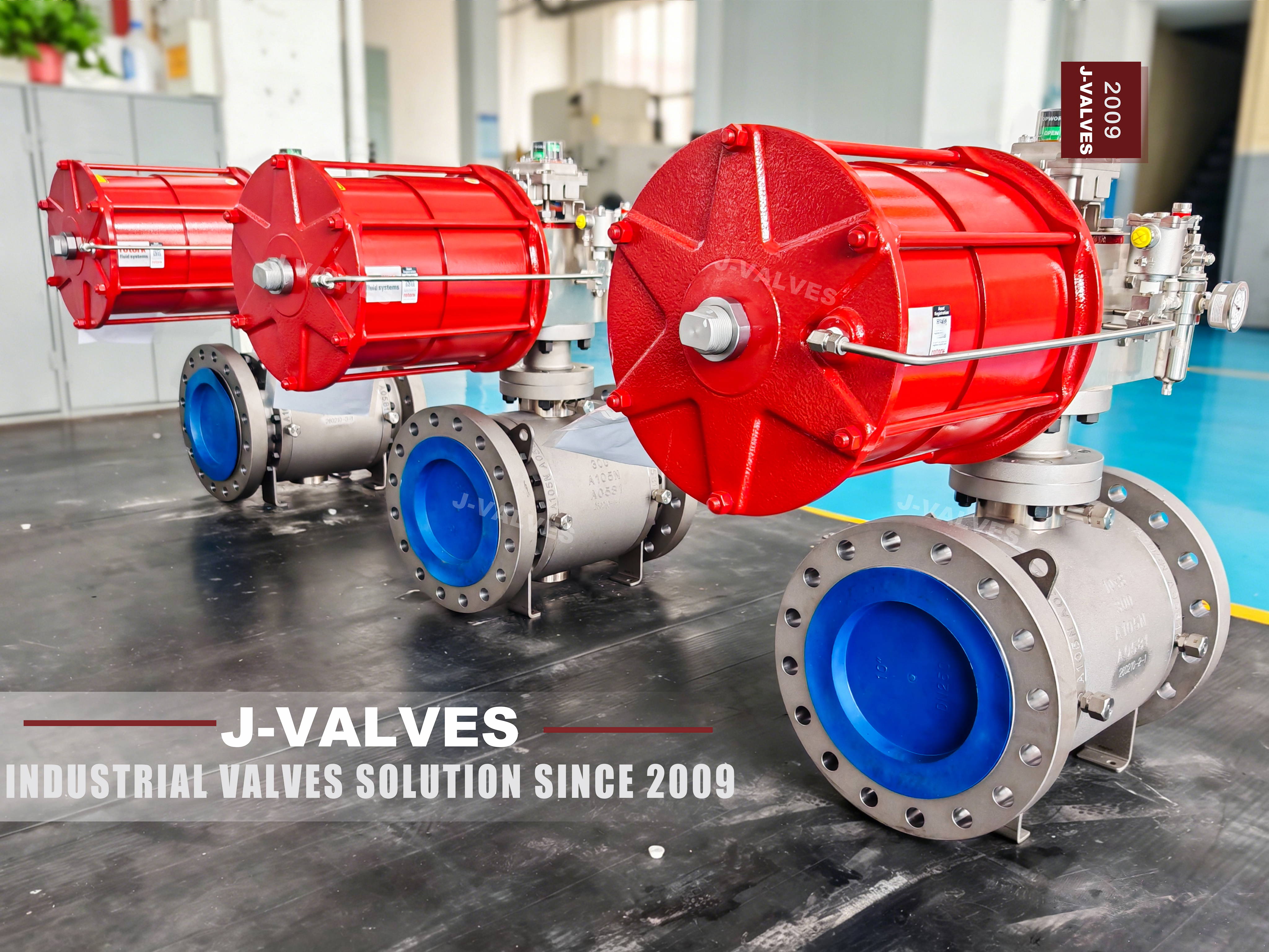
This is a valve and a machine sold as one item. The valve half is a forged three piece body with a trunnion mounted ball, flanged ends, Class 150 to 2500, DN50 to DN1400. The machine half is a pneumatic actuator that turns the stem a quarter turn on command. Between the two there is a set of parts that nobody photographs and everybody needs: a bracket, a coupling, an air supply that has been treated, and a way of telling the control system where the valve is.
That gap between the two halves is where quotations stop being comparable. One supplier quotes the valve and the actuator; another quotes the valve, the actuator, the mounting kit, the solenoid, the limit switch, the filter regulator and a cycle test. The difference in price is real and so is the difference in what arrives in the crate, and the specification is the only place it can be settled.
Design and Construction
The valve end is the standard three piece pattern: a centre body carrying the ball, both seats and the trunnion bearings, two side bodies carrying the flanges, and two bolted joints. The stem comes up through the bonnet and is retained against blowout, and the top of the stem is machined with a square or a keyed flat to take the coupling. Two of those parts are what the buyer actually operates, and neither of them appears in a product photograph.
The interface is where the two halves meet. The valve top flange is machined to an ISO 5211 size, the actuator has a matching flange and a female drive, and the bracket sets the height so that the two drives engage over the right length. That bracket is not a universal part: it is made for the valve stem height and the actuator spigot, which is why a bracket from one supplier rarely fits a valve from another maker without machining.

Material Options
The body follows the same material ladder as the manual version: A105 forged carbon steel as standard, A350 LF2 for low temperature, A182 F304, F316, F316L and F51 or F53 duplex for corrosive service. The ball, stem and seat move with it. Nothing about the actuation changes the material decision, and that is worth saying because buyers sometimes assume an actuated valve is a different product line.
The actuator has its own materials question. The housing is normally anodised aluminium for the smaller sizes and coated or stainless for offshore and corrosive atmospheres; the seals are NBR as standard with fluorocarbon or low temperature compounds as options; and the air ports and the solenoid are where a corrosive atmosphere attacks first. On a coastal or offshore site the actuator finish is specified separately from the valve body.
| Component | Standard Material | Optional Upgrade | Service Notes |
|---|---|---|---|
| Body and side bodies | ASTM A105 forged carbon steel, normalised | A350 LF2, A182 F304, F316, F51, F53 | three pieces, two bolted joints |
| Ball | A182 F304 with electroless nickel plating | F316, hard chrome, cobalt alloy hardfacing | carried on trunnions |
| Stem | A182 F316 | F316L, 17-4PH | square or keyed top for the coupling |
| Seat ring | RPTFE | PEEK, F316 with cobalt alloy hardfacing | spring loaded, self relieving |
| Mounting flange | ISO 5211 size for the valve | machined to the actuator spigot | the interface both sides must agree |
| Bracket and coupling | Made for the valve stem height and the actuator drive | not interchangeable between makers | checked for height and squareness |
| Actuator | Rack and pinion, double acting or spring return | scotch yoke for high torque | anodised aluminium or coated housing |
| Air supply | 0.4 to 0.7 MPa, filtered and regulated | dry air, dew point stated on the order | sized on the site pressure, not the maximum |
| Accessories | Solenoid, limit switch, filter regulator | positioner, quick exhaust, handwheel, air receiver | each needs its own area approval |
Technical Specifications
The envelope is DN50 to DN1400, Class 150 to 2500, three piece forged body, flanged RF or RTJ to ASME B16.5, face to face to ASME B16.10, pneumatic actuator double acting or spring return, air supply 0.4 to 0.7 MPa, and testing to API 598 and API 6D. Rack and pinion actuators cover the small and medium sizes; scotch yoke is used where the torque curve needs it at the larger ones.
Three fields in this block are part of the supply and are often left blank. The actuator size and model, because the torque figure comes from the valve test record rather than from a catalogue estimate; the air supply pressure actually available on site, because an actuator sized on 0.7 MPa that is fed 0.45 MPa will not open a valve at full differential; and the accessories list, which is quoted separately unless it is asked for.
| Item | Value |
|---|---|
| Nominal size | DN50 to DN1400 (2 to 56 inch) |
| Pressure class | Class 150 to 2500 (PN20 to PN420) |
| Body construction | three piece forged, two bolted joints |
| Body | ASTM A105 forged carbon steel |
| Body options | A350 LF2, A182 F304, F316, F316L, F51, F53 |
| Ball | A182 F304 with electroless nickel plating |
| Stem | A182 F316, blowout proof |
| Seat | RPTFE, spring loaded and self relieving |
| Seat options | PEEK, F316 with cobalt alloy hardfacing |
| End connection | RF flanged to ASME B16.5 |
| End option | RTJ flanged to ASME B16.5 |
| Face to face | ASME B16.10 for the size and class |
| Actuator | pneumatic, double acting or spring return |
| Actuator type | rack and pinion, or scotch yoke for high torque |
| Air supply | 0.4 to 0.7 MPa, filtered and regulated |
| Mounting | ISO 5211 flange with a square or keyed drive |
| Bracket | made for the valve stem height and the actuator spigot |
| Coupling | fitted and checked for engagement length |
| Accessories | solenoid, limit switch, filter regulator |
| Accessory options | positioner, quick exhaust, handwheel, air receiver |
| Failure position | stated on the order for a spring return unit |
| Design standard | API 6D, ASME B16.34, API 608 |
| Pressure test | API 598 and API 6D, shell 1.5 times, seat 1.1 times |
| Actuator sizing | from the valve torque record, not a catalogue estimate |
| Functional test | full cycles on air with the actuator fitted |
| Travel stops | set on the assembled unit, ball on seat at both ends |
| Area classification | applies to the solenoid and the switch |
| Packing | actuator braced for transport, accessories boxed with the unit |
| Material certificate | EN 10204 3.1 per heat |
| Marking | size, class, body material, heat number, temperature limits |
Standards and Compliance
The valve is covered by API 6D and ASME B16.34, with API 608 for the general ball valve items. The actuator interface is covered by ISO 5211 for the flange and drive, which is what makes a valve and an actuator from different makers mechanically compatible, and it is worth quoting on the order because it is the one interface both sides have to agree on.
The accessories bring their own certifications, and they are not valve certificates. A solenoid or a switch box going into a hazardous area needs its own approval for that area, and the valve being API 6D does not extend to it. On an order where the instruments are supplied with the valve, the area classification has to be stated so that the right certified accessories are fitted rather than the standard ones.
| Requirement | Standard | What J-VALVES Supplies |
|---|---|---|
| Pipeline valve requirements | API 6D | cavity relief, anti static, marking, test record |
| Pressure boundary | ASME B16.34 | wall thickness and rating |
| Ball valve requirements | API 608 | stem retention and marking |
| Actuator mounting interface | ISO 5211 | flange size, drive shape, spigot and bolt circle |
| Flanges | ASME B16.5 | RF or RTJ by class and size |
| Face to face | ASME B16.10 | long pattern for the class and size |
| Pressure testing | API 598 and API 6D | shell at 1.5 times, seat at 1.1 times |
| Instrument approval | area classification of the site | applies to the solenoid and switch, not to the valve |
Manufacturing Process
The valve is built and tested as a manual valve first, shell and seat, and the torque at breakaway and running is recorded. That record is what the actuator is sized from, with a margin for the service conditions, rather than a figure taken from a table by size and class. Only after that is the bracket fitted and the actuator mounted. That order matters: a valve that has already been cycled by an actuator is a valve whose breakaway torque is known rather than assumed.
Mounting is a fitting job, not an assembly job. The bracket is checked for height and squareness, the coupling is fitted to the stem and the actuator drive, and the travel stops are set so that the ball seats at both ends of the quarter turn rather than a few degrees short. The accessories are then piped and wired on the assembled unit, and the whole thing is cycled before it is packed.

Quality Control and Testing
The valve tests are the standard ones, shell at one and a half times and seat at one point one times in both directions. The tests that belong to the actuated unit are functional: a set number of full cycles on air with the actuator fitted, a check that the travel stops put the ball on its seat at both ends, a check of the spring return time where a single acting actuator is fitted, and a leak check on every pneumatic joint and fitting.
The accessories are checked as a system rather than as parts: the solenoid is operated from its own coil voltage, the limit switch is set and its contacts proved in both positions, and the filter regulator is set to the supply pressure stated on the order. A unit that cycles on the bench but has its limit switch set to the actuator stroke rather than the ball position will report open on a valve that is not open.
| Step | What Is Checked | Standard or Acceptance |
|---|---|---|
| Valve shell and seat test | before the actuator is mounted | API 598, both directions |
| Torque record | breakaway and running, with the valve as built | the figure the actuator is sized on |
| Bracket fit | height, squareness, drive engagement length | checked against the valve and the actuator |
| Travel stops | ball seats at both ends of the quarter turn | set on the assembled unit |
| Cycle test | full cycles on air with the actuator fitted | count stated on the order |
| Spring return | failure stroke time and final position | single acting units only |
| Air circuit | leak check on every fitting and tube | no drop over the hold time |
| Accessories | solenoid coil voltage, switch setting in both positions, regulator setting | proved against the ball position |
| Packing | unit protected for transport, actuator braced | accessories boxed with the unit |

Applications and Industry Service
The duty is remote or frequent operation of a pipeline or process isolation valve: emergency shutdown loops, pig trap and station isolation, tank farm manifolds, loading arms, and any valve that is opened on a sequence rather than by a person. It is also used where the valve is simply in a place nobody wants to walk to, which is a legitimate reason on a large site.
It is the wrong choice where there is no instrument air, where the air is wet or dirty, or where the valve has to be held in an intermediate position, which a quarter turn ball valve should not do anyway. Where the consequence of air failure is more serious than the consequence of the valve staying put, a spring return actuator is chosen and the failure direction is written down rather than assumed.

Installation, Operation and Maintenance
Bring treated air to the unit through a filter regulator, with the supply pressure in the range the actuator was sized for, and fit a check valve or an air receiver where the actuator has to complete a stroke after the supply is lost. On a horizontal line the actuator is a weight on the end of the valve, so the pipe is supported independently and the unit is not left hanging on the flange joint.
Set the travel stops on the actuator after the valve is on the line, not before, and prove the limit switches against the ball position. Keep the manual override accessible: a rack and pinion actuator normally has a declutchable handwheel or a top-mounted manual drive, and on a valve that is normally automated that override is the only way to move it during a power or air failure.
How to Specify and Order
An order needs the valve fields, then the actuation fields: actuator type, double acting or spring return, failure position, air supply pressure available on site, and the accessory list with the area classification. A typical line reads: eight inch, Class 300, body A105, full bore, RF flanged, RPTFE seat, spring return pneumatic actuator failing closed, air at 0.5 MPa, solenoid, limit switch, filter regulator, ISO 5211 mounting.
The five items that get left out and cannot be added later at the same price are the bracket, the coupling, the solenoid, the limit switch and the filter regulator. Ask for the torque record with the test documents as well: it is the figure the actuator was sized on, and without it a replacement actuator in five years is a guess. Left out of the quotation, each of them turns into a purchase order of its own a week before commissioning.
FAQ
Q: What is included when the valve is bought as pneumatic?
A: The valve, the actuator, the bracket and the coupling, and whatever accessories are named on the order. Solenoid, limit switch and filter regulator are usually quoted separately because the choice depends on the control system and the area classification. Ask for the accessory list to be written into the quotation, because a price comparison that leaves it out is not a comparison.
Q: Is the bracket universal?
A: No. The ISO 5211 flange and drive are standardised, but the bracket height depends on how far the valve stem sticks out above its top flange, and the spigot depends on the actuator. A bracket made for one maker valve generally will not fit another without machining, which is why the bracket should come with the valve rather than be sourced separately on site.
Q: How is the actuator size decided?
A: From the torque record of the valve as built, with a margin for the service conditions, and from the air pressure actually available on site. A size taken from a table by bore and pressure class is an estimate, and the estimate fails on the valves that are stiff: high differential pressure, long shutdown, or a metal seat.
Q: What happens when the air supply fails?
A: A double acting actuator stays where it is, because there is nothing to move it. A spring return actuator drives the valve to its failure position, open or closed as ordered. That direction has to be stated on the order, because the same valve with the same actuator can be supplied either way and the spring is inside the cylinder.
Q: Do the accessories need their own certification?
A: Yes. A solenoid or a switch going into a hazardous area needs approval for that area, and the valve being API 6D does not cover it. Where the instruments are supplied on the valve, the area classification and the supply voltage have to be on the order so that the correct certified parts are fitted rather than the standard ones.
Q: Can a manual override be fitted?
A: Yes, and on a normally automated valve it is worth having. A rack and pinion actuator usually takes a declutchable handwheel or a top mounted manual drive; a scotch yoke actuator often has a hydraulic manual pump. Whichever is chosen, the override has to be reachable with the insulation fitted.


Hot Products


News
Ball Valves in A Kraft Pulp Mill: Black Liquor, Green Liquor And The Cost of Choosing The Alloy by Habit
White liquor at pH 14 cracks carbon steel welds, black liquor sets solid below 100 C, green liquor dregs grind seats: alloy choice and torque in a kraft mill.
Read More
Slug Flow And Ball Valves: What Actually Arrives At The Seat
A slug is liquid mass with momentum, not a pressure spike. What changes at the seat, in the cavity and at the actuator when liquid reaches a ball valve.
Read More
Ball Valves in Direct Lithium Extraction: PH 1 Eluate, Gypsum Scale And 438,000 Cycles in Twenty-Five Years
Direct lithium extraction swings valves from pH 1 eluate to pH 12 caustic, 48 column switches a day and gypsum scale. Materials, seats and torque.
Read More
Ball Valves in Geothermal Brine: Silica Scale, Chloride Cracking And The Cooling Trap
Why geothermal brine destroys ball valves: retrograde silica scale, calcite at the flash point, chloride cracking above 60 C and the 250 C seat limit.
Read More