


CHINA J-VALVES Offers Various High-quality I ndustrial Ball Valves
J-VALVES, a distinguished professional ball valve manufacturer rooted in China, takes pride in its extensive product portfolio. Our offerings span a wide range, including trunnion-mounted ball valves, floating ball valves, high-temperature ball valves, high-pressure ball valves, metal-sealed ball valves, ultra-low temperature ball valves, DBB ball valves, Three-way And Four-way Ball Valve, and fully welded ball valves. Each product is a testament to our commitment to precision engineering and reliable performance. Meticulously crafted, they are designed to not only meet but exceed the most stringent industrial demands, ensuring stable operation even under extreme conditions. This enables us to provide our clients with high-value services and makes our valves widely sought-after in industries.
Product Category
Contact Us


-
J-VALVES-Q347F
-
J-VALVES
Overview of the J-VALVES 4x3 Inch 900LB A105N Three Piece Trunnion Ball Valve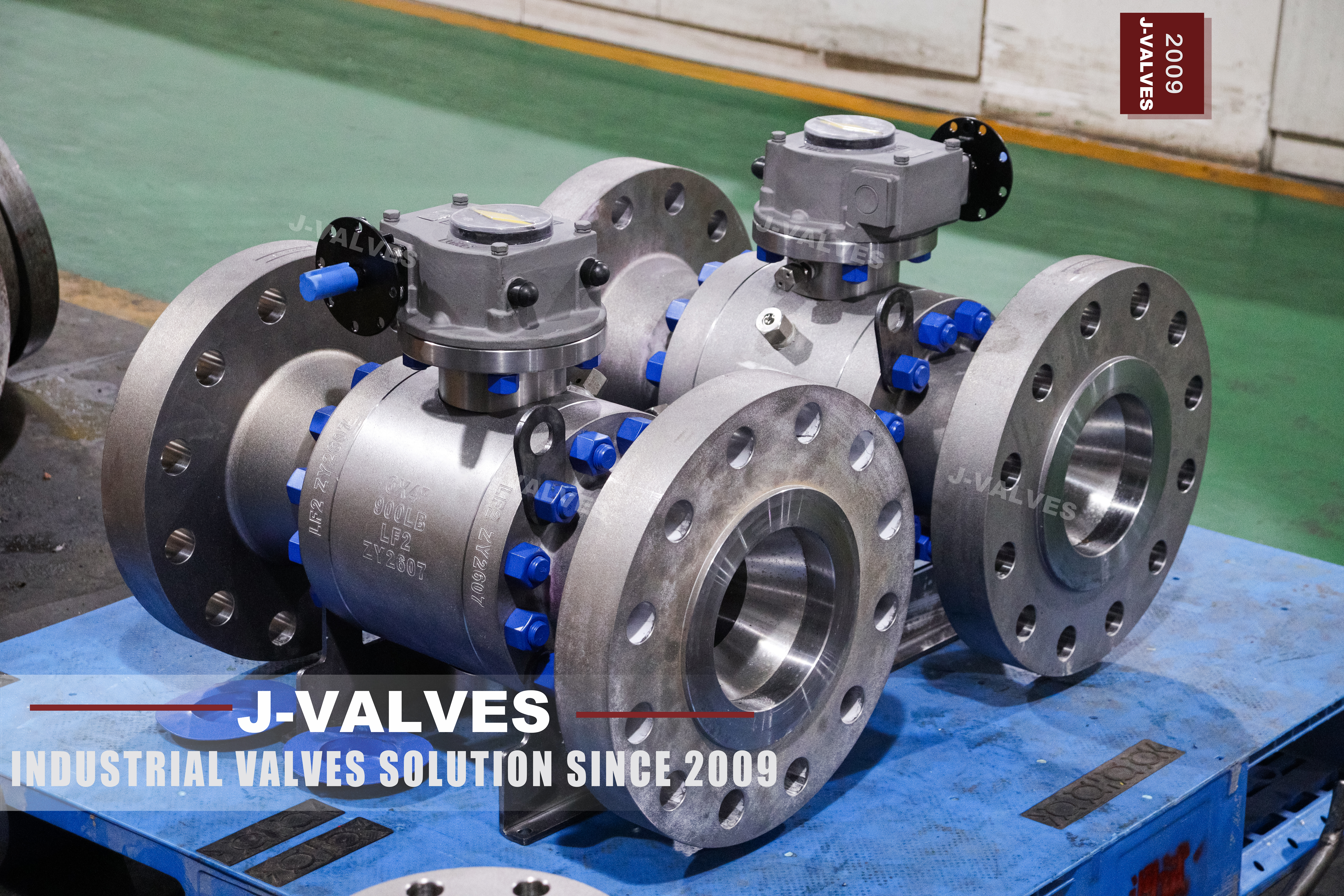
This is a four inch valve with a three inch bore, Class 900, forged in A105N and built in three bolted parts around a trunnion mounted ball. The four inch refers to the flanges, the three inch to the passage through the ball; the face to face and the flange drilling follow the four inch size, and the flow capacity follows the three. Both numbers have to appear on the order line.
The part of that description worth a page is the letter N. ASTM A105 allows a forging to be supplied in the as-forged condition, and the N suffix is what calls for normalising. At Class 900 in a four inch body the section is thick, and whether the forging was normalised is the difference between a uniform grain structure through the wall and one that varies with how fast each part cooled.
Design and Construction
Three parts: a centre body holding the ball, both seats and the trunnion bearings, and two side bodies carrying the flanges. The ball turns on a trunnion above and below in metal backed bearings, so the pressure load goes into the body through the bearings and the seats only seal. That is what lets a Class 900 valve of this size be turned by a gearbox instead of a larger actuator.
The reduced bore is a deliberate trade. A three inch passage inside a four inch body means less material, less weight and a lower operating torque than a full bore four inch valve, at the cost of a step at each end and a pressure drop that a full bore valve does not have. On a line that is never pigged, that is usually the right trade; on a line that is, it is the wrong valve.

Material Options
A105N is the body grade and the N is normalising, not an alloy addition. Normalising refines the grain, removes the forging stress and evens out the hardness across a thick section, which is why a high class forging is almost always ordered normalised. Where the drawing says only A105, the mill may ship as-forged and the certificate will still read A105, so the suffix has to be on the purchase order to be on the certificate.
Impact testing is a separate line on the order, not something A105N includes. Charpy tests are taken from the heat, at a stated temperature and in a stated orientation, and the result belongs to that heat rather than to the individual valve. Where the design temperature is low, or the specification asks for it, that test has to be written in and the test temperature fixed at the enquiry.
| Component | Standard Material | Optional Upgrade | Service Notes |
|---|---|---|---|
| Body and side bodies | ASTM A105N forged carbon steel, normalised | A350 LF2 for low temperature | three pieces, two bolted joints |
| Ball | A105N with hard chrome plating | 304, 316 stainless | carried on trunnions |
| Trunnion and bearings | 440C stainless in self lubricating bearings | nickel alloy bearings | takes the load off the seats |
| Stem | 17-4PH precipitation hardening stainless | 316 stainless | blowout proof, anti static |
| Seat ring | RPTFE, PEEK or PPL insert | A105N with cobalt alloy overlay for a metal primary seat | soft secondary, metal option |
| Packing | Flexible graphite | PTFE where the temperature allows | adjustable gland |
| Body gasket | Spiral wound stainless with graphite filler | ring type joint metal ring | new gasket at every opening |
| Body studs and nuts | A193 B7 with A194 2H | B7M with 2HM, B8M with 8M | high preload, three passes |
| Operator | Bevel gear or worm gear | pneumatic, electric, hydraulic | gear reduces the breakaway torque |
Technical Specifications
The envelope is four inch flanges by three inch bore, Class 900, three piece forged body in A105N, RF or RTJ flanges to ASME B16.5, face to face to ASME B16.10 on the four inch size, gear or bevel gear operator, and testing to API 598 and API 6D. Class 900 in the carbon steel group corresponds to 153 bar at 38 degrees in the ASME B16.34 table, and the rating falls away from there as the temperature rises.
Two things in this block are decided by the flange rather than the bore. The face to face is taken from the four inch column of B16.10, because the valve is measured between its flange faces and those are four inch flanges; and the flange drilling, bolt count and ring groove, where RTJ is ordered, all come from the four inch Class 900 row of B16.5. A three inch dimension applied to a four inch valve is the mistake this layout invites.
| Item | Value |
|---|---|
| Nominal size | 4 x 3 inch (DN100 flanges, DN80 bore) |
| Pressure class | Class 900 (PN150) |
| Body construction | three piece, two bolted joints |
| Body | ASTM A105N forged carbon steel |
| Heat treatment | normalised, the N suffix on the grade |
| Body option | A350 LF2 for low temperature |
| Ball | A105N with hard chrome plating |
| Ball options | 304, 316 stainless |
| Trunnion | upper and lower, 440C in self lubricating bearings |
| Stem | 17-4PH, blowout proof |
| Seat | RPTFE, PEEK or PPL insert |
| Seat option | A105N with cobalt alloy overlay as a metal primary seat |
| Packing | flexible graphite |
| Body gasket | spiral wound stainless with graphite filler |
| Gasket option | ring type joint metal ring |
| Body studs | ASTM A193 B7 |
| Nuts | ASTM A194 2H |
| End connection | RF flanged to ASME B16.5 Class 900 |
| End option | RTJ flanged to ASME B16.5 Class 900 |
| Face to face | ASME B16.10, four inch column |
| Bore | reduced bore, three inch through the ball |
| Rating at 38 C | 153 bar for carbon steel group 1.1 |
| Operator | bevel gear or worm gear |
| Operator options | pneumatic, electric, hydraulic |
| Design standard | ASME B16.34, API 6D, API 608 |
| Impact testing | per heat, at a stated temperature, only where ordered |
| Pressure test | API 598 and API 6D, shell 1.5 times, seat 1.1 times |
| Anti static | spring loaded path from ball to stem to body |
| Cavity relief | self relieving seat to the upstream side |
| Material certificate | EN 10204 3.1 with chemistry, mechanicals and heat treatment |
| Marking | size, class, body grade, heat number, temperature limits |
Standards and Compliance
ASME B16.34 sets the wall and the pressure temperature rating, API 6D adds the pipeline requirements, and API 608 covers the general ball valve items such as stem retention and marking. The forging is to ASTM A105 with the normalising called out, and the certificate is to EN 10204 3.1 with the heat number, the heat treatment and the mechanical properties on the same sheet as the chemistry.
At Class 900 the flange facing is a decision, not a default. A raised face is acceptable and common, but a ring joint is the usual choice for hydrocarbon and for anything where a leak is a hazard, and the two facings are not interchangeable: the ring groove, the gasket and the stud length all change, and a valve ordered with the wrong facing cannot be corrected on site.
| Requirement | Standard | What J-VALVES Supplies |
|---|---|---|
| Pressure boundary | ASME B16.34 | group 1.1 carbon steel, Class 900 = 153 bar at 38 C |
| Pipeline valve requirements | API 6D | cavity relief, anti static, marking, test record |
| Ball valve requirements | API 608 | stem retention and marking |
| Forging and heat treatment | ASTM A105 | the N suffix calls for normalising |
| Flanges | ASME B16.5 | four inch Class 900, raised face or ring joint |
| Face to face | ASME B16.10 | four inch column, not the three inch one |
| Pressure testing | API 598 and API 6D | shell at 1.5 times, seat at 1.1 times |
| Material certificate | EN 10204 3.1 | chemistry, mechanicals and heat treatment on one sheet |
Manufacturing Process
The forging is normalised before machining, and the normalising record is kept with the heat number so that it can be produced with the certificate years later. Machining is done with the joint faces, the seat pockets and the flange facing taken from common datums, because at Class 900 a seat pocket that is not square to the bore shows up as a seat that leaks on one side only.
The seat rings are machined, and where a metal seat is ordered the cobalt alloy overlay is welded, stress relieved and then lapped. Assembly follows the shell test: the body joints are made up on new gaskets and the valve is tested before the gearbox goes on, so that a joint failure does not damage an operator that has already been set. Nothing in that sequence can be resequenced once the overlay is on, so the route card follows the drawing revision rather than the workshop's convenience.

Quality Control and Testing
The forging is checked by composition and mechanical test per heat, with ultrasonic testing where the specification asks for it on a thick section. Normalising is verified from the heat treatment record, not from the hardness alone, because hardness can be right on a forging that was cooled in still air and never held at temperature. That distinction matters on a rejected heat: the parts are already forgings by then, and no amount of re-testing makes an unnormalised forging into a normalised one.
Every valve is shell tested at one and a half times the rating and seat tested at one point one times in both directions, with the cavity relief path checked separately. The dimensional check covers the four inch flange drilling, the four inch face to face, and the three inch bore, and all three are written on the inspection sheet because all three are read on arrival.
| Step | What Is Checked | Standard or Acceptance |
|---|---|---|
| Incoming forging | composition, mechanical properties, ultrasonic testing where specified | 3.1 certificate against A105N |
| Normalising | austenitising temperature, hold time, cooling record | heat treatment record kept with the heat number |
| Impact test | Charpy energy at the stated temperature, stated orientation | per heat, results on the certificate |
| Machining | seat pocket square to the bore, joint face flatness | common datums, measured on the face |
| Flange | four inch bolt circle, facing finish, ring groove profile | ASME B16.5 Class 900 |
| Body joints | stud grade, gasket, tightening sequence, final load | torque figure in three passes |
| Shell test | body and both joints at 1.5 times | API 598, no leak |
| Seat test | both directions at 1.1 times | API 598, judged by seat type |
| Dimensional | four inch face to face, four inch drilling, three inch bore | all three written on the inspection sheet |

Applications and Industry Service
The duty is high pressure isolation on gas and liquid lines where the flow does not need the full four inch passage: wellhead and manifold piping, injection skids, metering runs, compressor and pump discharge, and the block valve on a high pressure letdown station. The reduced bore suits those because the line is sized for pressure drop elsewhere and the valve is not the restriction that matters.
It is the wrong valve where the line will be pigged, where the medium carries solids that will settle in the step at each end, or where the pressure drop across the valve has been counted on the full bore figure. It is also the wrong valve below the temperature the seat can take, which on a soft seat is well above ambient and well below the forging limit.

Installation, Operation and Maintenance
Support the pipe on both sides and check that the flange faces are parallel before the studs are drawn up. On a Class 900 joint the stud load is high enough that a gap on one side will bend the flange rather than close, and the leak that follows is at the joint rather than at the seat. Where a ring joint is fitted, the ring is new every time the joint is opened and the groove is inspected for damage before it goes back.
Operate through the gearbox to the travel stops, fully open or fully closed, and do not use the handwheel as a lever against a stuck ball. For a seat change, isolate, vent, drain and take the line load off the spool before the side body studs are loosened; at this class the joint does not come apart politely under load. A ball that has been forced against its stop with a pipe wrench is a ball with a brinelled seat face, and it will leak from then on.
How to Specify and Order
An order needs both size numbers, the class, the body grade written as A105N, the heat treatment requirement, the impact test requirement with its temperature, the bore, the end facing, the seat construction, the operator and the standard. A typical line reads: 4x3 inch, Class 900, body A105N normalised, Charpy at minus 20, ring joint flanges, metal seat with a PEEK insert, bevel gear, API 6D with a 3.1 certificate.
The two lines that get left off and then cause a re-order are the impact test temperature and the flange facing. Neither can be added to a finished valve, and both are cheap at the enquiry stage. Where the valve is replacing an existing one, measure the face to face and the flange drilling on the old valve and put the figures on the order rather than relying on the class and size to imply them.
FAQ
Q: What does the N in A105N mean?
A: Normalised. ASTM A105 permits a forging to be supplied in the as-forged condition, and the N suffix calls for a normalising heat treatment, which refines the grain, removes forging stress and evens out hardness through a thick section. It is a heat treatment callout, not an alloy addition, and a forging ordered as A105 may legally arrive as-forged.
Q: If the drawing says A105, do I get A105N?
A: Not necessarily. The suffix has to be on the purchase order to appear on the certificate, and the certificate is what the inspector reads. On a Class 900 forging it is worth writing A105N explicitly and asking for the heat treatment record with the certificate, because the difference is invisible once the valve is machined.
Q: Is impact testing included with A105N?
A: No. Charpy testing is a separate requirement, taken from the heat at a stated temperature and in a stated orientation, and it appears on the certificate only when it has been ordered. If the design temperature is low or the specification calls for it, put the test temperature on the enquiry, because it cannot be added after the heat has been released.
Q: Which size governs the face to face and the flange?
A: The four inch size, because the valve is measured between its flange faces and the flanges are four inch. The three inch figure applies to the bore through the ball, which sets the flow capacity and the step at each end. Mixing the two is the classic error on a reduced bore valve, and it usually surfaces when the valve is already on site.
Q: Why is a reduced bore used at Class 900?
A: Because the smaller passage reduces material, weight and operating torque while still passing the flow the line needs, and the cost of that is a pressure drop and a step at each end. On a line that is never pigged and where the valve is not the limiting restriction, the trade is worth taking. On a pigged line it is not.
Q: Can the seat be changed in line?
A: The side body comes off with the valve still bolted in the line, which exposes one seat and the ball. The line still has to be isolated, vented, drained and supported first, and at Class 900 the joints are stiff enough that a spool under load will not come apart cleanly. It is a planned shutdown job, not a field repair.


Hot Products


News
Ball Valves in A Kraft Pulp Mill: Black Liquor, Green Liquor And The Cost of Choosing The Alloy by Habit
White liquor at pH 14 cracks carbon steel welds, black liquor sets solid below 100 C, green liquor dregs grind seats: alloy choice and torque in a kraft mill.
Read More
Slug Flow And Ball Valves: What Actually Arrives At The Seat
A slug is liquid mass with momentum, not a pressure spike. What changes at the seat, in the cavity and at the actuator when liquid reaches a ball valve.
Read More
Ball Valves in Direct Lithium Extraction: PH 1 Eluate, Gypsum Scale And 438,000 Cycles in Twenty-Five Years
Direct lithium extraction swings valves from pH 1 eluate to pH 12 caustic, 48 column switches a day and gypsum scale. Materials, seats and torque.
Read More
Ball Valves in Geothermal Brine: Silica Scale, Chloride Cracking And The Cooling Trap
Why geothermal brine destroys ball valves: retrograde silica scale, calcite at the flash point, chloride cracking above 60 C and the 250 C seat limit.
Read More