


CHINA J-VALVES Offers Various High-quality I ndustrial Ball Valves
J-VALVES, a distinguished professional ball valve manufacturer rooted in China, takes pride in its extensive product portfolio. Our offerings span a wide range, including trunnion-mounted ball valves, floating ball valves, high-temperature ball valves, high-pressure ball valves, metal-sealed ball valves, ultra-low temperature ball valves, DBB ball valves, Three-way And Four-way Ball Valve, and fully welded ball valves. Each product is a testament to our commitment to precision engineering and reliable performance. Meticulously crafted, they are designed to not only meet but exceed the most stringent industrial demands, ensuring stable operation even under extreme conditions. This enables us to provide our clients with high-value services and makes our valves widely sought-after in industries.
Product Category
Contact Us


-
J-VALVES-Q347F
-
J-VALVES
Overview of the J-VALVES CF8M Three Piece Flanged Trunnion Ball Valve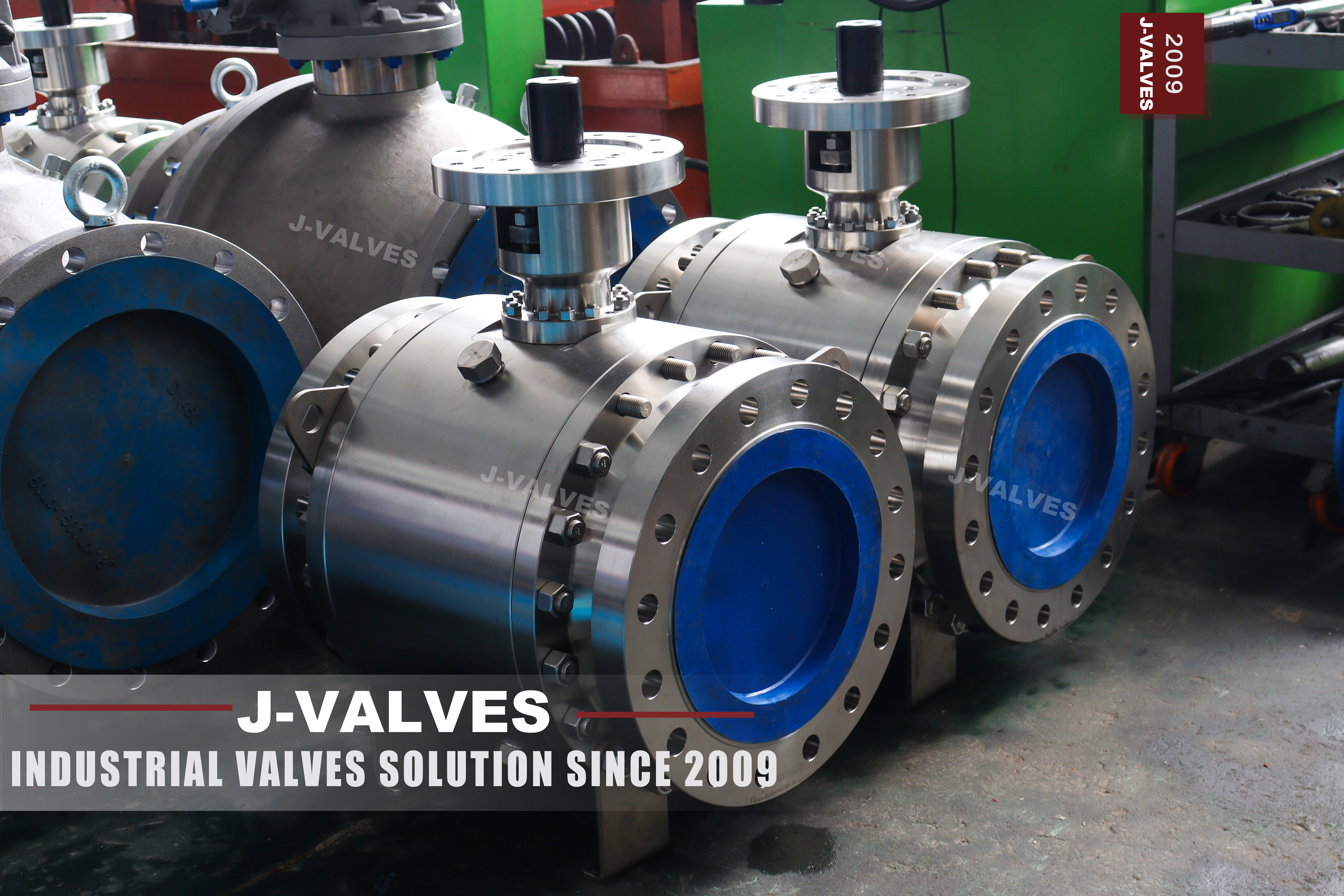
This is a three piece, flanged, trunnion mounted ball valve in CF8M stainless steel, covering 2 to 56 inch and Class 150 to 2500. CF8M is the cast designation, ASTM A351 CF8M, and it is the material shown in the photograph. The same valve can be supplied with a forged A182 F316 body where the size allows it. Ends are raised face or ring joint to ASME B16.5, the face to face length follows ASME B16.10, and the operator is a lever at small sizes and a worm gear from the larger ones.
The page exists because of one confusion that runs through the original listing. Its title and its keywords call this valve CF8M and forged at the same time. Those are two different product forms: CF8M is a casting grade under A351, F316 is a forging grade under A182. A body can be one or the other, never both, and on this size range the choice is mostly made for you. A 56 inch body is not forged, because there is no press and no billet for it that makes commercial sense.
What the trunnion does is worth stating plainly, because it is the reason this valve exists at these sizes. The ball is carried on a shaft above and below, so the line pressure no longer pushes it into the seat. The seats are pushed onto the ball by springs and by the pressure in the cavity, which keeps the seat load controlled and the torque low enough that a gear, rather than a hand, can operate a valve of this size.
Design and Construction
In a trunnion design the ball rotates on bearings and does not move along the axis. The sealing force comes from the seat assemblies: a spring ring pushes each seat towards the ball at low pressure, and once the line is pressurised the medium acts on the seat piston to add to that force. Because the ball is held in place, the seat load does not grow with the square of the bore the way it does in a floating valve, which is what makes 24 and 36 inch sizes practical at all.
The body is three pieces: a centre section that carries the trunnion bearings and the stem, and two end caps bolted to it. The photograph shows the bolted joints with their studs and the two support feet welded to the body, which are there so the valve does not hang its own weight on the pipe. The centre section is also where the cavity relief and the drain or vent connections live, and where the injection fitting sits if the seats are ordered with one.
The seat can be single piston effect or double piston effect, and the difference is not cosmetic. With double piston effect the seat seals in both directions and cavity pressure pushes both seats outward, so the cavity relieves to either side of the valve. With single piston effect the cavity relieves only one way and the upstream seat is relieved by design. Which one is fitted has to be stated on the order, because it changes the part inside the same body.
The stem enters through the centre section, is retained so that it cannot be blown out by cavity pressure, and carries an anti static path from the ball to the body. On the larger sizes the stem top is machined for a worm gear with a handwheel, and the gear is bolted to a mounting flange that also accepts a pneumatic or electric actuator of the same pattern.

Material Options
CF8M is the cast austenitic stainless grade with molybdenum, the casting equivalent of 316. It is the standard body material here because it can be produced in the wall sections and sizes this valve covers, and because a casting can be radiographed and, within the rules of the standard, repaired. Which of the two is supplied is not a preference: it is a cast versus forged question decided by size and by the inspection route the project asks for. F316 is the forged equivalent and is offered at the smaller sizes and higher classes, where a forging is practical and where the tighter grain structure and the absence of cast defects are worth the cost.
The choice changes the paperwork as much as the metal. A casting is proven by radiography and by a heat treatment record; a forging is proven by ultrasonic inspection and by the reduction ratio from the billet. Both arrive with an EN 10204 3.1 certificate. Where the body will be welded, CF3M or F316L is the low carbon option that avoids sensitisation, and a duplex or super austenitic grade is available on request where chlorides or seawater rule out the 300 series.
| Component | Standard Material | Optional Upgrade | Service Notes |
|---|---|---|---|
| Body and end caps | ASTM A351 CF8M cast stainless | A182 F316 forged, CF3M, duplex on request | cast at large sizes, forged at small |
| Ball | CF8M with ENP | Hard chrome, tungsten carbide spray | coating is the wear surface |
| Trunnion and bearings | F316 with surface hardening, or 17-4PH | Stainless with a bearing sleeve | carries the ball, not the seat |
| Stem | 17-4PH | F316 with ENP, nickel alloy | blowout proof, anti static |
| Seat ring | RPTFE | PTFE, PPL, PEEK, metal with graphite | single or double piston effect on order |
| Seat spring | Stainless steel | Nickel alloy for corrosive duty | sets the low pressure seal |
| Body gasket | Graphite spiral wound with stainless hoop | Metal ring gasket for ring joint | new gasket at every body joint |
| Operator | Lever to 6 inch, worm gear above | Pneumatic, electric, hydraulic | chosen on measured torque |
Technical Specifications
The envelope is 2 to 56 inch, Class 150 to 2500, three piece flanged body, raised face or ring joint, face to face to ASME B16.10, lever or gear, tested to API 598 with a fire test to API 607 where it is ordered. Butt weld ends to ASME B16.25 are available instead of flanges. The size that ships is the one confirmed on the general arrangement drawing, together with the flange drilling, the face to face length and the operator.
Three numbers decide the build. The bore decides whether the valve is full port or reduced, and a reduced bore trunnion valve is shorter and cheaper but will not pass a pig. The class decides the wall and the flange drilling, and it is the class that has to match the line rather than the pump. The operator is decided by the measured torque, which is why the gear is not chosen from a table but from the torque record issued with the drawing.
| Item | Value |
|---|---|
| Size range | 2 to 56 inch (DN50 to DN1400) |
| Pressure range | Class 150 to 2500 (PN20 to PN420) |
| Body construction | three piece, bolted end caps |
| Ball support | trunnion mounted, bearings above and below |
| Body material | ASTM A351 CF8M cast stainless steel |
| Body option | ASTM A182 F316 forged stainless steel |
| Low carbon option | CF3M or F316L where the body is welded |
| Alloy option | duplex or super austenitic on request |
| Material group | ASME B16.34 group 3.1 austenitic |
| Ball | CF8M with electroless nickel plating |
| Ball options | hard chrome, tungsten carbide spray |
| Trunnion | F316 surface hardened or 17-4PH |
| Stem | 17-4PH |
| Stem options | F316 with ENP, nickel alloy |
| Temperature basis | set by the seat compound; body group 3.1 rated to 538 C |
| Seat | RPTFE |
| Seat options | PTFE, PPL, PEEK, metal with graphite |
| Seat effect | single or double piston effect, stated on order |
| Body gasket | graphite spiral wound with stainless hoop |
| End connection | flanged raised face to ASME B16.5 |
| End options | ring joint to ASME B16.5, butt weld to ASME B16.25 |
| Face to face | ASME B16.10 |
| Bore | full port or reduced bore |
| Wall thickness | ASME B16.34 |
| Design standard | API 6D |
| Fire test | API 607 where ordered |
| Pressure testing | API 598 shell and seat, both directions |
| Operator | lever to 6 inch, worm gear above |
| Operator options | pneumatic, electric, hydraulic |
| Support | welded feet on the body for the larger sizes |
| Anti static | path from ball to stem to body |
| Cavity relief | through the seat, direction set by the seat effect |
| Documentation | EN 10204 3.1, API 6D document package on request |
Standards and Compliance
ASME B16.34 sets the wall and the rating. CF8M and F316 are both austenitic stainless steels, which B16.34 places in material group 3.1, with a rating table that runs from minus 254 to plus 538 degrees Celsius. API 6D governs the trunnion design and the pipeline documentation set: the fire test, the anti static requirement, the cavity relief and the marking. API 598 covers the pressure test, and ASME B16.5 the flange.
API 608 appears on many listings of this valve and is worth putting in its place. It is a general purpose ball valve standard, and it is quoted here because the same body pattern is sold at smaller sizes where it applies. At 24 inch and Class 900 the governing document is API 6D, and a buyer who needs the pipeline package should ask for API 6D by name rather than assume that a valve carrying the API 608 reference already has it.
| Requirement | Standard | What J-VALVES Supplies |
|---|---|---|
| Wall thickness and rating | ASME B16.34 | group 3.1 austenitic, Class 150 to 2500 |
| Trunnion design and documentation | API 6D | fire test, anti static, cavity relief, marking |
| Fire safety where ordered | API 607 | fire test certificate |
| Flange dimensions and facing | ASME B16.5 | raised face as standard, ring joint on request |
| Face to face length | ASME B16.10 | length confirmed on the drawing |
| Butt weld ends where ordered | ASME B16.25 | end preparation drawing |
| Pressure testing | API 598 | shell at 1.5 times, seat at 1.1 times, both directions |
| Material certificate | EN 10204 3.1 | certificate per heat number, casting or forging |
Manufacturing Process
The castings are produced to a pattern that includes the flange, the body joint and the trunnion bores, then solution annealed to restore corrosion resistance after casting. The machined surfaces are the flange faces, the body joints, the seat pockets, the trunnion bores and the stem bore, and the seat pockets and trunnion bore are cut in one setting so that the ball axis and the seat faces stay concentric.
The ball is machined, ground, polished and then coated, by electroless nickel, hard chrome or a tungsten carbide spray, depending on the duty. Assembly runs from the centre section outward: trunnion and bearings, ball, seats and springs, then the end caps on their gaskets and the studs taken up in a cross pattern to the specified torque. The gear is fitted last and the travel is set so that the ball stops dead at open and at closed.

Quality Control and Testing
Castings are inspected before machining: visual and dimensional first, then radiography or dye penetrant on the body and the joint faces according to the inspection level ordered. Positive material identification is run on every body and on the trim, because CF8M and CF3M look identical and the certificate is only as good as the check that the right heat went into the right casting, and that no repair was made outside the approved welding procedure.
Each assembled valve is shell tested at one and a half times the rating, with the body joints and the gland included in the test, and seat tested at one point one times in both directions. The cavity relief is proven by pressurising the cavity, and the operator is checked for full quarter turn travel with the stops set. Torque is measured and recorded, and the figure goes out with the drawing because it is what an actuator has to be sized on.
| Step | What Is Checked | Standard or Acceptance |
|---|---|---|
| Incoming casting | heat number, chemistry, radiography or penetrant | EN 10204 3.1 against A351 CF8M, inspection level as ordered |
| Forged body where ordered | chemistry, ultrasonic inspection, reduction ratio | A182 F316 with mill certificate |
| Positive material identification | body and trim alloy check | 100 percent, recorded against the certificate |
| Machining | seat pocket and trunnion bore concentricity | drawing tolerance, checked in one setting |
| Flange gauge | outside diameter, bolt circle, hole diameter, facing | ASME B16.5 for the class ordered |
| Shell test | body, both body joints and the gland at 1.5 times | API 598, no leak |
| Seat test | each seat in both directions at 1.1 times | API 598, no visible leak |
| Cavity relief | cavity pressurised with the valve closed | relieves as the seat effect ordered |
| Torque and gear | breakaway torque, gear travel and stops | recorded, stops set at open and closed |

Applications and Industry Service
The duty is isolation on water, desalination, chemical, pulp and paper, power and general process lines where a stainless body is needed because the medium or the environment would attack carbon steel. It is also the standard choice for a line that has to be pigged, because a full port trunnion valve passes the tool, and for a line where the valve is large enough that a floating design would need an unreasonable amount of torque.
It is not the answer for abrasive slurry, where a metal seated or a different valve type is better, and it is not the cheapest answer for a small line that is operated twice a year, where a floating valve does the same job with fewer parts. Being clear about those two boundaries is more useful to a buyer than any claim about performance in general.

Installation, Operation and Maintenance
Support the valve on its feet rather than letting the pipe carry it, and leave the flange bolts accessible, because on a three piece body the end caps have to come off for a seat change and that is done in line. On a ring joint flange, use a new ring gasket every time and make sure the groove is clean and undamaged; a reused ring is the most common cause of a leak on a high pressure joint that was tight on the bench.
Operate the valve fully open or fully closed. A trunnion valve left part open puts the seat and the ball coating into the flow, and the damage is not visible until the valve will not seal. Grease the seats through the injection fitting only where the seats are ordered with one, and only with the grease the certificate names, because the wrong grease can swell the seat insert and turn a working valve into a seized one.
How to Specify and Order
State size, class, body grade and form, ball and seat trim, seat effect, end type and facing, face to face standard and operator. A typical line reads: 12 inch, Class 300, body A351 CF8M, ball CF8M with ENP, RPTFE seat, double piston effect, raised face flanges to ASME B16.5, face to face to ASME B16.10, worm gear. Name the inspection level for the castings as well, because radiography is ordered, not assumed.
Send the medium, the design pressure and temperature, the pipe schedule and whether the line will be pigged. The medium decides between CF8M and a duplex grade, the temperature decides the seat, the pipe schedule decides whether a full port body fits the space, and the pigging requirement decides whether a reduced bore can be considered at all. Those four answers close most of the specification before any drawing is issued.
FAQ
Q: Is CF8M a cast or a forged material?
A: CF8M is a casting grade. It is ASTM A351 CF8M, the cast austenitic stainless with molybdenum, and it is the cast equivalent of 316. The forged equivalent is ASTM A182 F316. A body is one or the other, never both, and a listing that calls the same valve CF8M and forged at once is describing two different supply forms rather than one valve.
Q: Can I get a forged body at 24 inch?
A: In practice, no. Forgings at that size require a billet and a press that do not exist for the cost a valve can carry, so the body is cast CF8M. Forging is offered where it makes sense, which is the smaller sizes and the higher classes, and there the benefit is a tighter grain structure, no cast defects and a different inspection route.
Q: What is double piston effect?
A: With double piston effect each seat seals in both directions and the cavity pressure pushes both seats outward, so the cavity relieves to either side of the valve. With single piston effect the cavity relieves in one direction only and the upstream seat is relieved by design. Both are built into the same body, so the choice belongs on the order and not in a later conversation.
Q: Should I choose raised face or ring joint flanges?
A: Raised face is the default and covers most duties. Ring joint is chosen where the class is high, the medium is hazardous or the consequence of a leak is severe, and it needs a matching groove in the mating flange and a new ring gasket at every joint. A ring gasket is not reusable, and a reused one is the most common cause of a leak on a joint that was tight on the bench.
Q: Why is a gear operator fitted instead of a lever?
A: Because of the torque. At these sizes the torque needed to break the valve away after a long closed period is beyond what a hand lever can supply comfortably, and a gearbox multiplies it into a range a person can turn. The gear is selected on the measured torque of the assembled valve, which is why the torque record goes out with the drawing.
Q: Do I need API 6D?
A: If the valve goes into a pipeline or into a project where a third party inspects the documentation, yes, and it should be asked for by name. API 6D brings the fire test, the anti static requirement, the cavity relief and a document package. For a general process line that needs a sound valve rather than a documented one, the same body is supplied without that package.


Hot Products


News
Ball Valves in A Kraft Pulp Mill: Black Liquor, Green Liquor And The Cost of Choosing The Alloy by Habit
White liquor at pH 14 cracks carbon steel welds, black liquor sets solid below 100 C, green liquor dregs grind seats: alloy choice and torque in a kraft mill.
Read More
Slug Flow And Ball Valves: What Actually Arrives At The Seat
A slug is liquid mass with momentum, not a pressure spike. What changes at the seat, in the cavity and at the actuator when liquid reaches a ball valve.
Read More
Ball Valves in Direct Lithium Extraction: PH 1 Eluate, Gypsum Scale And 438,000 Cycles in Twenty-Five Years
Direct lithium extraction swings valves from pH 1 eluate to pH 12 caustic, 48 column switches a day and gypsum scale. Materials, seats and torque.
Read More
Ball Valves in Geothermal Brine: Silica Scale, Chloride Cracking And The Cooling Trap
Why geothermal brine destroys ball valves: retrograde silica scale, calcite at the flash point, chloride cracking above 60 C and the 250 C seat limit.
Read More