


CHINA J-VALVES Offers Various High-quality I ndustrial Ball Valves
J-VALVES, a distinguished professional ball valve manufacturer rooted in China, takes pride in its extensive product portfolio. Our offerings span a wide range, including trunnion-mounted ball valves, floating ball valves, high-temperature ball valves, high-pressure ball valves, metal-sealed ball valves, ultra-low temperature ball valves, DBB ball valves, Three-way And Four-way Ball Valve, and fully welded ball valves. Each product is a testament to our commitment to precision engineering and reliable performance. Meticulously crafted, they are designed to not only meet but exceed the most stringent industrial demands, ensuring stable operation even under extreme conditions. This enables us to provide our clients with high-value services and makes our valves widely sought-after in industries.
Product Category
Contact Us


-
J-VALVES-Q347F
-
J-VALVES
Overview of the J-VALVES DN250 Class 600 A105 Three Piece Trunnion Ball Valve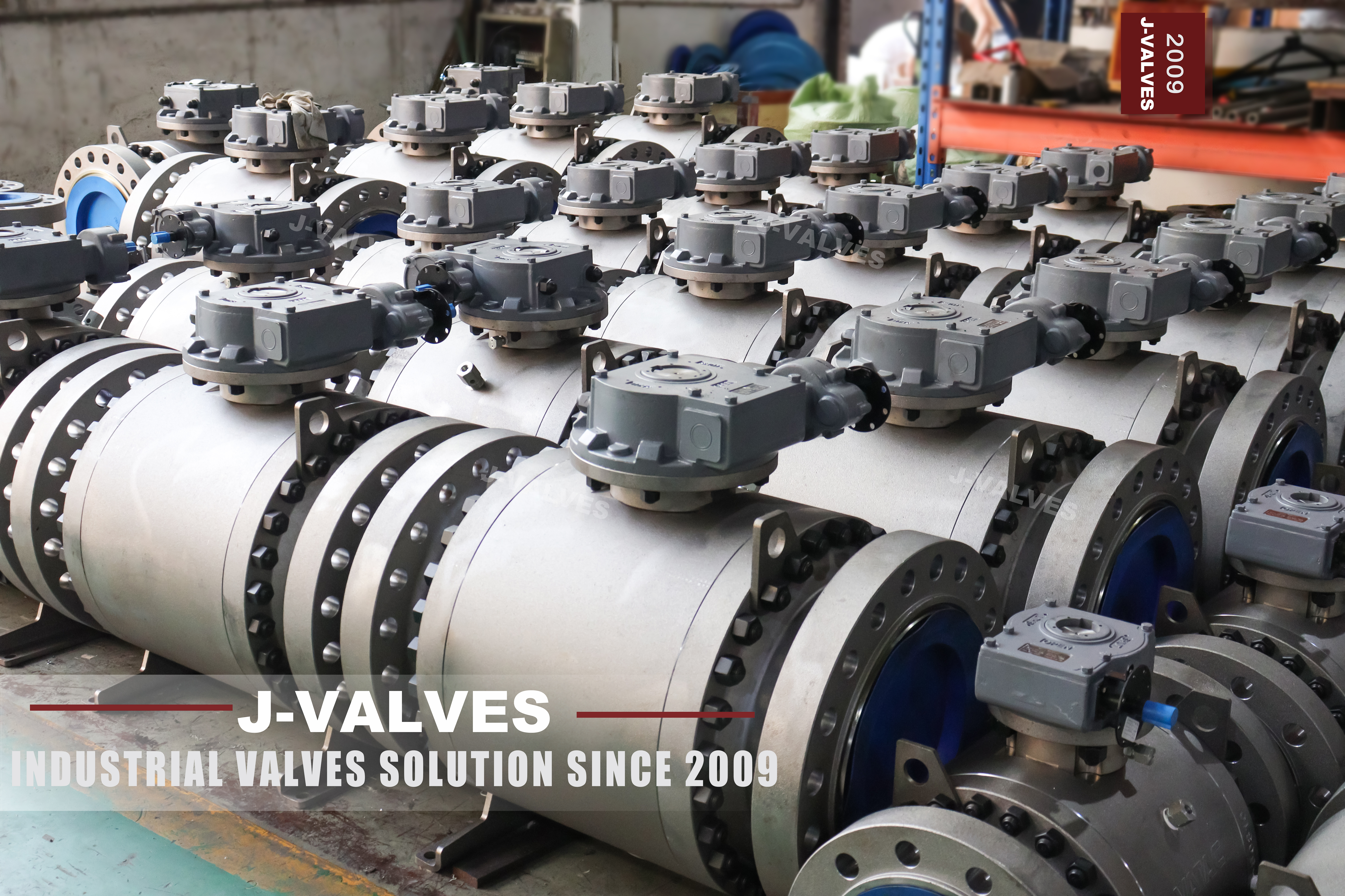
This is a ten inch, Class 600, three piece forged trunnion mounted ball valve. DN250 is the nominal size, PN100 is the same class expressed in the pressure code system, the body is forged A105 carbon steel, the ends are flanged to ASME B16.5, and the design follows API 6D. The ball is carried on trunnions, the operator is a worm gear with a handwheel, and the centre section comes out between two bolted joints.
That last feature is the reason this valve exists in this form. A two piece body opens at one end cap and the ball comes out that way; a three piece side entry body lifts the whole centre section and leaves the two end caps bolted to the pipe. At DN250 Class 600 the body is heavy enough that the difference matters: one version means handling a large end cap against the pipe, the other means lifting a centre section straight up on a gantry or a chain block.
Design and Construction
The trunnion takes the pressure load off the seats. The line pressure acts on the ball and, instead of pushing the ball onto the downstream seat, is carried through an upper and a lower trunnion into bearings in the body. The seats are spring loaded, so they seal against the ball at low pressure and are then assisted as the pressure rises. At DN250 that arrangement is what keeps the ball from deforming and what keeps the operating torque inside a gear rather than a lever.
The three piece layout puts two bolted joints in the pressure boundary, one each side of the centre section. That is the cost of the design and it is a real one: two joints to make, two gaskets to replace, two sets of studs to torque. What it buys is that the ball, both seats and the stem packing are all reachable by removing the centre section, without disturbing either flange connection to the pipe, which on a welded spool is the difference between a workshop job and a pipe cut.

Material Options
The body is forged A105. At DN250 and Class 600 that is a deliberate choice rather than a default: a forging has no casting porosity in the pressure boundary, its grain flow follows the shape, and the sections that carry the joint load are homogeneous, which matters on a design with two bolted joints. A216 WCB is perfectly serviceable at lower classes and is cheaper; A350 LF2 is the low temperature grade, and A182 F304 or F316 are the stainless options for corrosive product.
The trim is carbon steel with a protective coating as standard. The ball is A105 with electroless nickel plating, with hard chrome, HVOF tungsten carbide or a cobalt alloy overlay where the duty is abrasive. The trunnion is A105 with surface hardening or 17-4PH, the stem is 17-4PH or A105 with ENP, and the packing is flexible graphite reinforced with a nickel alloy wire, which is the normal choice at this class because it holds its volume through a thermal cycle.
| Component | Standard Material | Optional Upgrade | Service Notes |
|---|---|---|---|
| Body and end caps | ASTM A105 forged carbon steel | A350 LF2, A182 F304, A182 F316 | forged body at this class, stainless for corrosive product |
| Ball | A105 with electroless nickel plating | Hard chrome, HVOF tungsten carbide, cobalt alloy overlay | coating decides life on abrasive product |
| Trunnion and bearings | A105 with surface hardening | 17-4PH trunnion | carries the load so the seat does not |
| Stem | 17-4PH or A105 with ENP | F304 or F316 for the stainless build | blowout proof, retained by the body |
| Seat ring | PTFE or RPTFE | PEEK, metal with cobalt alloy facing | metal seat above the polymer limit |
| Body joint gasket | Spiral wound, graphite filled | PTFE filled for lower temperature | two joints, both replaced at every opening |
| Stem packing | Flexible graphite, wire reinforced | PTFE V-ring for lower temperature | fire safe result rests on the graphite |
| Operator | Worm gear with handwheel | Pneumatic, electric, hydraulic | sized on measured torque |
Technical Specifications
The envelope is DN250, Class 600 which is PN100, three piece forged body, flanged to ASME B16.5, face to face to ASME B16.10, trunnion mounted ball, worm gear operated, with a shell and seat test to API 598. The bore is full port unless a reduced bore is ordered, and on a ten inch valve that choice changes the weight as much as the flow area.
The figure that matters most on the drawing is the face to face length, because it is fixed by ASME B16.10 for the size and class and a spool built to a different figure cannot be closed by pulling the flanges. The second is the torque, which is measured on the assembled valve and issued with the drawing: at Class 600 it moves with the seat compound, the temperature and the pressure, and a gear selected on a catalogue figure is how a valve ends up unable to open against its own seat.
| Item | Value |
|---|---|
| Nominal size | DN250 (10 inch) |
| Pressure rating | Class 600 (PN100) |
| Body construction | three piece, forged, bolted centre section |
| Ball support | upper and lower trunnion in bearings |
| Body material | ASTM A105 forged carbon steel |
| Body options | A350 LF2, A182 F304, A182 F316 |
| Ball | A105 with electroless nickel plating |
| Ball options | hard chrome, HVOF tungsten carbide, cobalt alloy overlay |
| Trunnion | A105 with surface hardening, or 17-4PH |
| Stem | 17-4PH precipitation hardening stainless |
| Stem option | A105 with ENP, F304, F316 |
| Seat | PTFE or RPTFE |
| Seat options | PEEK, metal with cobalt alloy facing |
| Seat loading | spring loaded, self relieving |
| Bore | full port unless reduced bore ordered |
| Body joint gasket | spiral wound, graphite filled |
| Packing | flexible graphite, wire reinforced |
| End connection | flanged to ASME B16.5 |
| Face to face | ASME B16.10 |
| Wall thickness | ASME B16.34 |
| Design standard | API 6D and API 608 |
| Pressure testing | API 598 shell and seat, both joints, both directions |
| Operator | worm gear with handwheel as standard |
| Operator options | pneumatic, electric, hydraulic |
| Anti static | spring loaded path from body to stem to ball |
| Stem retention | blowout proof, retained by the body |
| Body cavity | self relieving through the seat |
| In line service | centre section removable without disturbing the pipe flanges |
| Fire safe | API 607 / ISO 10497 where required |
| Documentation | EN 10204 3.1 per section, test record, GA drawing |
Standards and Compliance
API 6D governs the pipeline requirements, including the design document, the cavity relief rule and the documentation package that a pipeline operator expects. API 608 covers the ball valve specifics that apply regardless: the anti static path, the blowout proof stem and the nameplate content. ASME B16.34 supplies the wall and the rating, ASME B16.5 the flange, ASME B16.10 the length and API 598 the test.
The three piece body adds a documentation point of its own. Because there are two pressure boundary joints, the drawing has to show the joint detail, the gasket type and the bolt grade for each, and the test has to prove both joints. On a two piece body there is one joint to declare; on this valve there are two, and an inspector will look for both on the drawing and both on the test record.
| Requirement | Standard | What J-VALVES Supplies |
|---|---|---|
| Pipeline valve requirements | API 6D | design document, GA drawing, joint detail, test record |
| Ball valve specifics | API 608 | anti static path, blowout proof stem, nameplate content |
| Wall thickness and rating | ASME B16.34 | wall calculation for DN250 Class 600 |
| Flange dimensions and facing | ASME B16.5 | raised face or ring joint as ordered |
| Face to face length | ASME B16.10 | length measured end to end and recorded |
| Pressure testing | API 598 | shell and seat, both joints proved, both directions |
| Fire safe where required | API 607 / ISO 10497 | certificate naming seat and packing |
| Material certificate | EN 10204 3.1 | certificate per heat number for all three body sections |
| Marking | API 6D nameplate | size, class, body grade, heat number, tag number |
Manufacturing Process
The body is forged in three sections: two end caps and a centre section. Each is machined so that its joint face is square to the bore and parallel to its partner, because a three piece body has two joints that both have to close on a gasket at the same time and a mismatch in either shows up as a leak. The seat pockets and the trunnion bores are machined in one setting so the ball axis and the seat axis stay concentric.
Assembly is a sequence rather than a single operation: seats and ball into the centre section, end caps on with their gaskets, studs torqued in a cross pattern in stages, stem in from the top with the packing compressed to a set load, and the gear fitted last. The assembled valve is torqued and the figure recorded, and the gear stops are set on the valve rather than on the gear housing.

Quality Control and Testing
Every valve is shell tested at one and a half times the rating and seat tested at one point one times in both directions to API 598. On a three piece body the shell test is applied with both joints made up as they will be in service, because the joints are part of the pressure boundary and a test that bypasses them proves nothing. Both joints are checked visually and by pressure hold.
The dimensional record covers the things that are specific to this design: parallelism of each joint face to its partner, the face to face length end to end, the flange dimensions to ASME B16.5, and the bore. The torque is measured last on the assembled valve and recorded against the gear selection, and the gear is checked for full travel with the stops set on the valve.
| Step | What Is Checked | Standard or Acceptance |
|---|---|---|
| Incoming forging | heat number and grade for all three sections | EN 10204 3.1, no grade substitution between sections |
| Joint faces | parallelism of each face to its partner, squareness to the bore | surface plate check, drawing tolerance |
| Seat and trunnion bores | concentricity of the ball axis and the seat axis | machined in one setting, checked after |
| Flange gauge | outside diameter, bolt circle, bolt hole diameter, facing | ASME B16.5 Class 600, gauged |
| Shell test | body and both joints at 1.5 times, joints made up as in service | API 598, no leak at either joint |
| Seat test | each seat in both directions at 1.1 times | API 598, no visible leak |
| Torque | breakaway and running torque on the assembled valve | recorded and issued with the drawing |
| Gear function | full travel with the stops set on the valve | reaches both stops, no fouling |
| Marking | nameplate against the order line | size, class, A105, heat number for each section |

Applications and Industry Service
The duty is isolation on oil and gas lines, refinery and petrochemical process piping, and plant headers at Class 600, where the valve is large enough that in-line service access is worth paying for. It is also used where a line cannot be cut: a three piece body lets the seats be changed with the end caps still bolted to the pipe, which on a welded or a coated line is often the deciding factor.
The forged body suits high pressure and, where the grade is changed to F304 or F316, corrosive product. It does not suit abrasive slurries at this class unless a hardfaced trim is ordered, and it is not a throttling valve: a partly open trunnion ball at DN250 puts the seat edge into a high velocity stream and erodes it locally and quickly. Where a line needs throttling, a separate control valve is fitted and this valve stays as the isolation block either side, which is also what lets the control valve be serviced on its own.

Installation, Operation and Maintenance
Support the pipe either side of the valve, leave vertical clearance above the centre section for lifting it out, and align the flanges before pulling any stud up. On a three piece body the studs at both joints are torqued in a cross pattern in stages to the gasket maker figure; pulling one joint up fully before the other distorts the centre section and is a common cause of a joint that weeps after a thermal cycle.
Operate the gear through the full quarter turn rather than part of it, and do not use the handwheel to force a valve that has jammed. When the seats are serviced, replace both joint gaskets and the stem packing as well, because the joints that were opened are the ones that will weep first, and a seat change that reuses an old gasket turns a two hour job into a repeat visit.
How to Specify and Order
An order for a three piece valve carries two fields that a two piece order does not: the bore, full port or reduced, and whether the pad is machined for an actuator now or later. Both change the casting and the machining, so neither can be added once the body is made. The rest of the line is conventional: DN250, Class 600, A105 forged body, ball A105 with ENP, PTFE seat, raised face to ASME B16.5, face to face to ASME B16.10, worm gear.
Send the fluid, the design pressure and temperature, whether the line will be pigged, and whether the valve will be actuated later. Pigging decides full port against reduced bore, the fluid and temperature decide the trim, and the actuation question decides whether the mounting pad is machined for an actuator at build stage rather than adapted on site. Those four answers keep the order on schedule.
FAQ
Q: Why choose three piece over two piece at this size?
A: Because the centre section lifts out and leaves both end caps bolted to the pipe. At DN250 Class 600 the body is heavy enough that handling an end cap against the pipe is a rigging job, while lifting a centre section straight up is straightforward. The price is two pressure boundary joints instead of one, and both have to be made and tested properly.
Q: Is the forged body necessary at DN250 Class 600?
A: It is the better choice at this class. A forging has no casting porosity in the pressure boundary, its grain flow follows the shape, and the sections that carry the joint load are homogeneous, which matters on a design with two bolted joints. A216 WCB is perfectly sound at lower classes and is what many buyers order there; A105 is the standard at Class 600.
Q: What does PN100 mean here?
A: It is the same class expressed in the pressure code system: Class 600 is PN100. The two are different notations for one rating rather than two different products, and the valve is marked according to whichever system the order names. The pipe flange will match either, as long as the standard is stated.
Q: Can the seats be changed without cutting the line?
A: Yes, that is the point of the three piece body. With the line isolated and drained, the centre section is unbolted and lifted out, and the ball, both seats and the stem packing are accessible. The pipe flanges are never disturbed, so no spool has to be cut and no pipe has to be re-aligned afterwards.
Q: Should I order full port or reduced bore?
A: Full port if the line is pigged or if the pressure drop matters, reduced bore if weight and cost matter more and nothing has to pass through. On a ten inch valve the difference in weight is significant, which is why the bore is a field on the order rather than an assumption.
Q: What torque figure will the gear be sized on?
A: The measured breakaway and running torque of the assembled valve, issued with the drawing. It is not a catalogue constant: it moves with the seat compound, the temperature and the pressure, and a gear chosen on a table figure is how a valve ends up unable to open against its own seat load after a few months closed.


Hot Products


News
Ball Valves in A Kraft Pulp Mill: Black Liquor, Green Liquor And The Cost of Choosing The Alloy by Habit
White liquor at pH 14 cracks carbon steel welds, black liquor sets solid below 100 C, green liquor dregs grind seats: alloy choice and torque in a kraft mill.
Read More
Slug Flow And Ball Valves: What Actually Arrives At The Seat
A slug is liquid mass with momentum, not a pressure spike. What changes at the seat, in the cavity and at the actuator when liquid reaches a ball valve.
Read More
Ball Valves in Direct Lithium Extraction: PH 1 Eluate, Gypsum Scale And 438,000 Cycles in Twenty-Five Years
Direct lithium extraction swings valves from pH 1 eluate to pH 12 caustic, 48 column switches a day and gypsum scale. Materials, seats and torque.
Read More
Ball Valves in Geothermal Brine: Silica Scale, Chloride Cracking And The Cooling Trap
Why geothermal brine destroys ball valves: retrograde silica scale, calcite at the flash point, chloride cracking above 60 C and the 250 C seat limit.
Read More