


CHINA J-VALVES Offers Various High-quality I ndustrial Ball Valves
J-VALVES, a distinguished professional ball valve manufacturer rooted in China, takes pride in its extensive product portfolio. Our offerings span a wide range, including trunnion-mounted ball valves, floating ball valves, high-temperature ball valves, high-pressure ball valves, metal-sealed ball valves, ultra-low temperature ball valves, DBB ball valves, Three-way And Four-way Ball Valve, and fully welded ball valves. Each product is a testament to our commitment to precision engineering and reliable performance. Meticulously crafted, they are designed to not only meet but exceed the most stringent industrial demands, ensuring stable operation even under extreme conditions. This enables us to provide our clients with high-value services and makes our valves widely sought-after in industries.
Product Category
Contact Us


-
J-VALVES-Q347F
-
J-VALVES
Overview of the J-VALVES 16 Inch Class 300 Two Piece Trunnion Mounted Ball Valve
The J-VALVES 16 inch (DN400) Class 300 two piece trunnion  mounted ball valve is a full bore pipeline isolation valve in ASTM A216 WCB cast carbon steel, with ASME B16.5 flanges and ASME B16.10 face to face length, designed to API 6D under the rating and wall thickness rules of ASME B16.34.
At this bore the trunnion design is a requirement, not a preference. At Class 300, line pressure puts roughly 595 kN on the seat face across a 385 mm bore, which a floating ball would press onto the downstream seat and into the stem, pushing torque past what any gearbox can move. A trunnion valve carries that thrust in upper and lower bearings, so the stem sees torque only.
The body is a two piece bolted construction with one main joint, so the ball and both seats can be reached once the line is isolated. The bore is full and circular, so the valve adds no pressure drop and a pig passes without meeting a step.
Design and Construction
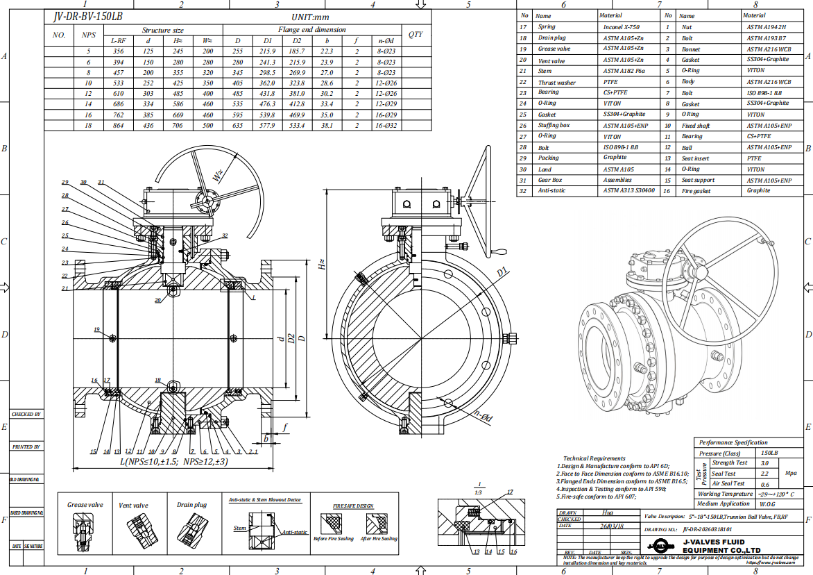
The body is a two piece bolted split design: two cast halves joined on one machined joint with a spiral wound gasket and a ring of bolts, leaving a single main pressure joint to control.
The ball turns on upper and lower trunnions, each in a metal backed self lubricating bearing, normally 440C stainless or Inconel. The bearings take the side load line pressure puts on the ball, keeping torque low and stable as pressure rises.
The seats are spring energised rings. With single piston effect, upstream pressure pushes the seat onto the ball while downstream pressure pulls it away, so cavity overpressure relieves into the lower pressure side. With double piston effect, pressure on both sides pushes the seat toward the ball for double isolation both ways, but cavity overpressure must then be released externally.
The stem is separate from the ball, so it carries torque only. It is retained by the body so it cannot be ejected if the gland is disturbed, two O rings plus a graphite gasket give a triple barrier, and an anti-static device keeps the path from ball to stem to body at 10 ohm or less.
Material Options
The standard body material is ASTM A216 WCB cast carbon steel, which under ASME B16.34 group 1.1 covers -29 C to 425 C for water, oil, gas and general process service.
| Component | Standard Material | Optional Upgrade | Service Notes |
|---|---|---|---|
| Body and bonnet | A216 WCB cast carbon steel | CF8M, CF3M, LCC, duplex, nickel alloy | WCB covers -29 C to 425 C |
| Ball | A105N or WCB with hard chrome | 304 or 316 stainless, ENP | Chrome resists scoring under seat load |
| Stem | 17-4PH precipitation hardening stainless | A182 F316 | Separate from the ball, carries torque only |
| Seat | PTFE | RPTFE, PPL, metal seat with Stellite facing | Seat grade sets the temperature limit |
| Trunnion bearing | 440C stainless, self lubricating | Inconel alloy | Takes the side load from line pressure |
| Body gasket | Spiral wound SS316 with graphite filler | PTFE coated | Seals the single main body joint |
| Stem seal | Two O rings plus a graphite gasket | Low emission set to ISO 15848-1 | Triple barrier at the stem |
| Operator | Worm gear with handwheel | Pneumatic, electric or hydraulic | Sized on measured torque plus a 1.3 to 1.5 factor |
The ball is WCB or A105N with hard chrome plating, or 304 and 316 stainless where corrosion resistance matters more than hardness. The chrome layer, 0.05 to 0.10 mm at about 800 to 1000 HV, resists scoring as the seat loads against the ball at full differential pressure.
Seat material sets the temperature limit of the valve, not the body material. PTFE and RPTFE are good to about 200 C, PPL extends the range to about 260 C, and above that the valve needs metal seats with a hard faced ring. On a WCB valve rated to 425 C, the soft seat gives out long before the casting.
Technical Specifications
The table lists the standard build; values change with the seat grade, end connection or operator.
| Item | Value |
|---|---|
| Nominal size | 16 inch (DN400) |
| Bore | 385 mm full bore; API 6D minimum for NPS 16 Class 150 to 600 |
| Pressure class | ASME Class 300 (about PN50 by conversion) |
| Body style | Two piece bolted split body, trunnion mounted ball |
| Body material | ASTM A216 WCB cast carbon steel |
| Ball and stem | Hard chrome plated WCB or A105N; 17-4PH stem |
| Seat material | PTFE, RPTFE, PPL or metal seat with Stellite facing |
| End connection | ASME B16.5 Class 300 flange, 648 mm OD, 571.5 mm bolt circle, 20 bolts |
| Face to face | 838 mm to ASME B16.10 long pattern; 610 mm short pattern |
| Operation | Gearbox, 90 degree travel, clockwise to close |
| Pressure rating | 51.1 bar (740 psi) at 38 C, 38.0 bar (551 psi) at 425 C |
| Temperature range | To 200 C with PTFE or RPTFE, to 260 C with PPL, body ceiling 425 C |
| Shell test | API 6D and API 598, 1.5 x rated, 76.7 bar |
| Seat test | API 6D and API 598, 1.1 x rated, 56.2 bar, both seats both directions |
| Operating torque | 3400 to 7200 N m reference, measured on each valve |
| Anti-static | 10 ohm or less from ball to stem to body |
| Fire safe | API 607 / ISO 10497 |
Standards and Compliance
The design basis is API 6D, the pipeline valve standard, which carries the requirements for double block and bleed, the body and seat test, the anti-static path and fire safe qualification. ASME B16.34 supplies the pressure temperature rating and minimum wall thickness. API 608, which also appears on many quotations for this product, is the general industrial ball valve standard, not the right basis for a large bore pipeline trunnion valve.
| Requirement | Standard | Supplied |
|---|---|---|
| Pipeline valve design | API 6D | Yes |
| Pressure rating and wall thickness | ASME B16.34 | Yes |
| Face to face and end to end | ASME B16.10 | Yes |
| Flange dimensions and drilling | ASME B16.5 | Yes |
| Shell and seat test | API 598 and API 6D | Yes |
| Fire safe test | API 607 / ISO 10497 | Yes |
| Fugitive emission | ISO 15848-1 | Optional |
| Sour service material | NACE MR0175 / ISO 15156 | On qualification |
| Material certificate | EN 10204 3.1 | Yes |
For this size, ASME B16.34 group 1.1 rates the body at 51.1 bar (740 psi) at 38 C, falling to 44.1 bar at 200 C, 42.5 bar at 300 C and 38.0 bar at 425 C. The drop from 38 C to 300 C is about 17 percent, so a valve chosen from the cold rating alone is over rated in a hot line. API 6D sets the shell test at 1.5 times the 38 C rating, or 76.7 bar, and the seat test at 1.1 times it, or 56.2 bar.
The Class 300 rating converts to about PN50, which is why many quotations write this size as DN400 PN50. Two things about that shorthand matter. PN50 is not a standard rating in EN 1092-1, which lists PN 2.5, 6, 10, 16, 25, 40, 63, 100, 160, 250 and 400 but no PN50. And Class and PN are two different systems: a Class 300 flange and a PN40 or PN63 flange of the same size differ in outside diameter, bolt circle and thickness, and will not bolt together without an adapter.
Fire safe behaviour follows API 607 and ISO 10497: a 750 C to 800 C flame for 30 minutes, cooling, then a repeat seat leakage test. The metal backing behind the soft seat carries the seal after it is destroyed, a containment claim rather than a promise the valve stays operable after a fire.
Manufacturing Process
A valve of this size starts at the foundry. The WCB castings are heavy section, and a sound body needs the pour controlled so the flange necks, trunnion bores and body joint face are free of shrinkage.
J-VALVES runs this chain in house at its Wenzhou and Lishui plants, which cover a 15000 square metre manufacturing base with 40 CNC lathes, 5 machining centres and 8 drilling machines. The seat pockets, the trunnion bores and both flange faces are machined against drawings, because the alignment between the two trunnion bearings governs how freely the ball turns and therefore the operator torque.
Assembly then fits the trunnions and bearings, the seats, the ball, the stem and the body joint, each to a controlled bolt torque. Every valve is pressure tested on the bench and its torque recorded before packing.

Quality Control and Testing
Each valve follows an eight step sequence from incoming material to packed valve, and every measurement is tied to the heat number so the certificates and test report form one package.
| Step | What Is Checked | Standard or Acceptance |
|---|---|---|
| Incoming material | Heat number, chemistry, mill certificate | EN 10204 3.1 |
| Casting inspection | Soundness at the flanges, body joint and trunnion bores | Drawing, 100 percent on the heat |
| PMI before machining | Alloy identity where an alloy body is supplied | 100 percent on alloy bodies |
| Machining dimension | 385 mm bore, seat pockets, 838 mm face to face | ASME B16.10, drawing |
| Trunnion and bearing fit | Bearing clearance, ball rotation, breakaway torque | Smooth rotation, torque recorded |
| Shell strength test | Body and joint at 1.5 x rated | API 6D, 76.7 bar, no leak |
| Seat test | Both seats at 1.1 x rated, both directions | API 6D, 56.2 bar, zero visible leak |
| Coating, marking, documents | Film thickness, heat number tag, certificate set | Spec, EN 10204 3.1 set |
Shell testing holds the assembled body at 76.7 bar with water while the body joint and flange faces are checked for weeping. Seat testing applies 56.2 bar to each seat in turn in both directions, and a soft seated valve is rejected on any visible leakage, the rate A criterion of ISO 5208. Bearing fit and ball rotation are checked during assembly and breakaway torque recorded for every valve.

Applications and Industry Service
The valve is specified where a large line has to be isolated positively rather than modulated. Transmission and gathering lines use it as a sectioning valve, and because the bore is full and circular a pig passes without meeting a step. Tank farms and pump stations use it where a positive block is needed before maintenance, a duty where the DN400 size usually matches the adjacent line flange rating rather than a genuine pressure need. The boundary is in the seat, not the body: PTFE or RPTFE suits clean oil, gas and water to about 200 C, while an abrasive medium, a temperature above 260 C or a fire exposed location calls for a metal seated version with a hard faced seat ring.
Installation, Operation and Maintenance
Before installation, clean the flange faces and bore, cycle the valve once and check that the body joint bolts and gland are tight. The valve is bidirectional, so it fits either way, but a valve of this size needs its own support, because the flange bolts should not carry its weight alone.
Operation is by gearbox, normally a worm gear with a handwheel, or by pneumatic, electric or hydraulic actuator. Actuator sizing must use the measured torque, not a catalogue figure, with a safety factor of about 1.3 to 1.5, because breakaway torque depends on the seat grade, the service and how long the valve has stood still.
In service the seats are the wear items. Where a seat begins to pass, the emergency sealant injection fitting can restore the seal temporarily, but the seat must be replaced at the first opportunity. To replace a seat, isolate and vent the line, drain both sides, confirm the body cavity is depressurised, then open the body joint. Both seats are replaced as a set with a new body gasket. Opening the body joint breaks the pressure boundary, so the valve must never be worked on under pressure; follow the specified bolt torque and sequence on reassembly.
How to Specify and Order
Give the size and class, the body and trim material, the seat material, the end connection and the operator. State the design standard, API 6D, with ASME B16.34 for the rating, and the test standard, API 598. Where a European standard line joins the valve, name the flange standard as well as the pressure rating so the drilling pattern is not assumed from the class number. Say whether the service is sour, so any NACE MR0175 / ISO 15156 qualification is settled before the order.
Standard builds are accepted from one piece, with 2 to 4 weeks for a standard build and 4 to 8 weeks custom. Every order ships with an EN 10204 3.1 material certificate, a dimensional report, a pressure test report carrying the torque and anti-static records, and a packing list. Export packing is a wooden case with the bore plugged and the flange faces protected.
FAQ
Q: What is the pressure rating of a 16 inch Class 300 trunnion ball valve?
A: An A216 WCB body under ASME B16.34 group 1.1 is rated at 51.1 bar (740 psi) at 38 C. The rating falls to 44.1 bar at 200 C, 42.5 bar at 300 C and 38.0 bar at 425 C, so the working pressure must be checked against the actual line temperature, not the cold rating. The soft seat sets a lower limit again: PTFE and RPTFE are good to about 200 C and PPL to about 260 C.
Q: Why does a 16 inch valve need a trunnion mounted ball instead of a floating ball?
A: At Class 300 the line pressure puts roughly 595 kN on the seat face across a 385 mm bore. A floating ball would press that load onto the downstream seat and the stem, so the torque would rise past what a gearbox can move and the seat would wear quickly. A trunnion valve carries the load in upper and lower bearings, which keeps the torque low and stable and lets the stem carry torque only.
Q: Is PN50 the same as Class 300?
A: No. Class 300 converts to about PN50 by pressure, but PN50 is not a standard rating in EN 1092-1, which lists PN 2.5, 6, 10, 16, 25, 40, 63, 100, 160, 250 and 400 but no PN50. Class and PN are also different flange systems: a Class 300 flange and a PN40 or PN63 flange of the same size differ in outside diameter, bolt circle and thickness, and will not bolt together without an adapter.
Q: What is the difference between single piston effect and double piston effect seats?
A: With single piston effect the upstream pressure pushes the seat onto the ball while the downstream pressure pulls it away, so cavity overpressure relieves into the lower pressure side automatically. With double piston effect the pressure on both sides pushes the seat toward the ball, which gives double isolation in both directions but means cavity overpressure must be released by an external relief device.


Hot Products


News
Ball Valves in A Kraft Pulp Mill: Black Liquor, Green Liquor And The Cost of Choosing The Alloy by Habit
White liquor at pH 14 cracks carbon steel welds, black liquor sets solid below 100 C, green liquor dregs grind seats: alloy choice and torque in a kraft mill.
Read More
Slug Flow And Ball Valves: What Actually Arrives At The Seat
A slug is liquid mass with momentum, not a pressure spike. What changes at the seat, in the cavity and at the actuator when liquid reaches a ball valve.
Read More
Ball Valves in Direct Lithium Extraction: PH 1 Eluate, Gypsum Scale And 438,000 Cycles in Twenty-Five Years
Direct lithium extraction swings valves from pH 1 eluate to pH 12 caustic, 48 column switches a day and gypsum scale. Materials, seats and torque.
Read More
Ball Valves in Geothermal Brine: Silica Scale, Chloride Cracking And The Cooling Trap
Why geothermal brine destroys ball valves: retrograde silica scale, calcite at the flash point, chloride cracking above 60 C and the 250 C seat limit.
Read More