


CHINA J-VALVES Offers Various High-quality I ndustrial Ball Valves
J-VALVES, a distinguished professional ball valve manufacturer rooted in China, takes pride in its extensive product portfolio. Our offerings span a wide range, including trunnion-mounted ball valves, floating ball valves, high-temperature ball valves, high-pressure ball valves, metal-sealed ball valves, ultra-low temperature ball valves, DBB ball valves, Three-way And Four-way Ball Valve, and fully welded ball valves. Each product is a testament to our commitment to precision engineering and reliable performance. Meticulously crafted, they are designed to not only meet but exceed the most stringent industrial demands, ensuring stable operation even under extreme conditions. This enables us to provide our clients with high-value services and makes our valves widely sought-after in industries.
Product Category
Contact Us


-
J-VALVES-Q47H
-
J-VALVES
Overview of the J-VALVES 6 Inch PN420 Three-Piece Trunnion Ball Valve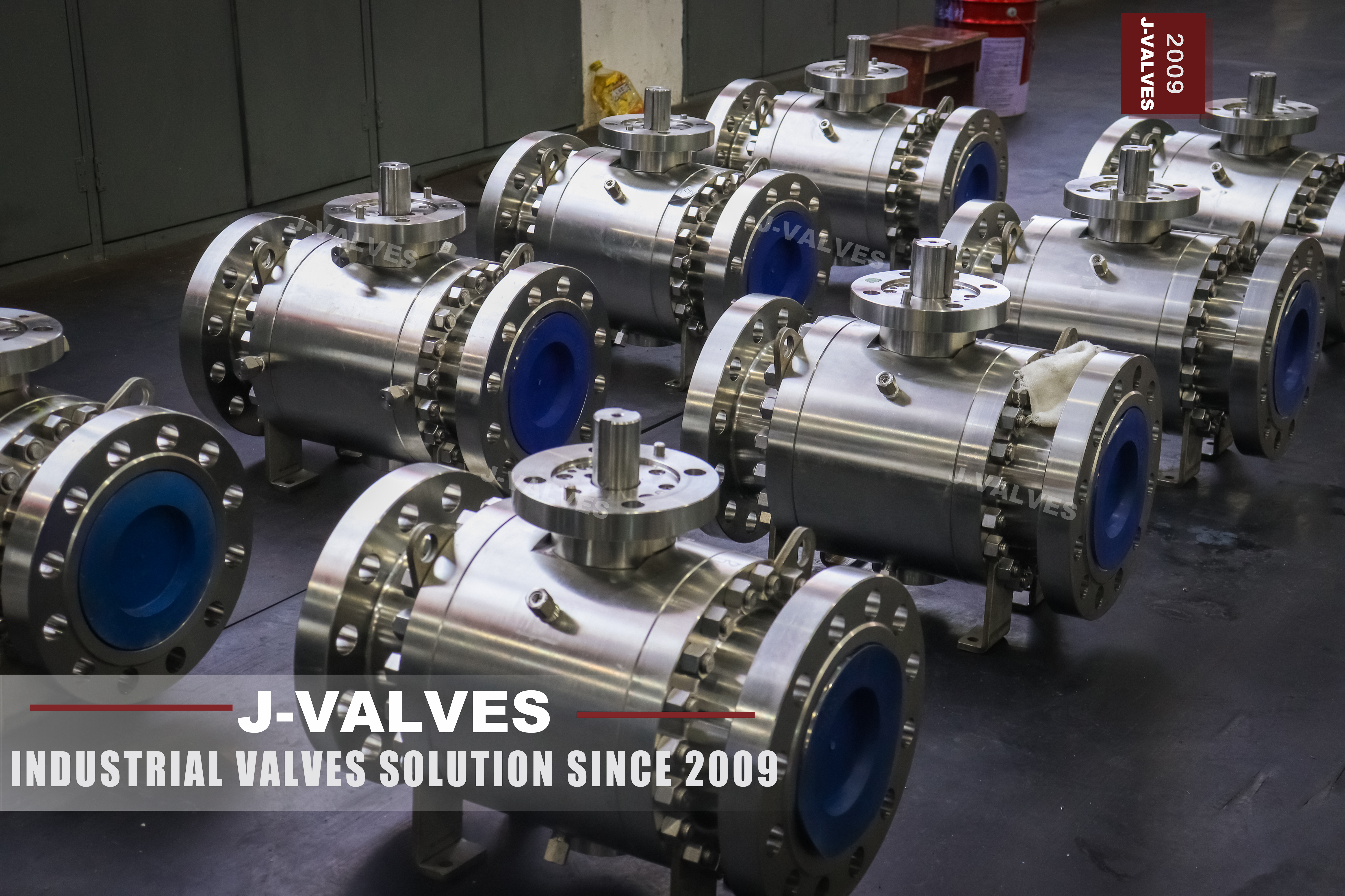
This is a six inch, DN 150, Class 2500 pipeline valve in forged austenitic stainless steel, built as a three-piece side entry body with a trunnion mounted ball and ring joint flanges. Every element of it answers the same condition: the line runs at 413.7 bar, and nothing in the design may depend on an elastomer, or on line pressure alone holding the ball into a seat.
PN 420 is the top of the API 6D list. Clause 7.2 runs the metric designations from PN 20 for Class 150 through PN 50, PN 64, PN 100, PN 150 and PN 250 to PN 420 for Class 2500, so a nameplate reading PN 420 and an order reading 2500 LB describe one rating, and the number is a designation rather than a pressure in bar. In ASME B16.34 group 2.2, which covers A182 F316, Class 2500 allows 413.7 bar at 38 C; a carbon steel body in group 1.1 allows 425.5 bar at the same temperature. The alloy buys corrosion resistance, not pressure, and it costs a little rating.
Three-piece construction at this class is worth stating plainly rather than selling as an unmixed advantage. Two bolted body joints sit on the pressure boundary at 414 bar, two more potential leak paths than a welded body has, and the reason to accept them is access: both caps stay on the pipe and the centre section lifts out. Where the line cannot be opened, or the valve is buried or subsea, a welded or top entry body is the better answer, and this page is written for the case where access is the requirement.
Design and Construction
The body is a centre section with a cap bolted to each end, all three machined from forgings rather than cast. At six inch the ball runs on an upper and a lower trunnion, and both trunnions sit in bearing blocks separate from the end caps. The trunnions absorb the side load line pressure puts on the ball, so the stem transmits torque and nothing else, and the seats never hold the ball against a load that rises with pressure. The alignment datum stays in the centre section, the part that is never taken apart.
Sealing is by two independent seat rings, spring loaded against the ball, so the valve holds at low pressure before line pressure builds. Above that the seat type decides how the cavity behaves, which is where a Class 2500 order is most often specified loosely. A single piston effect seat is pushed onto the ball by upstream pressure and pulled away by downstream pressure, so overpressure from thermal expansion of trapped liquid escapes to the low pressure side and the cavity is self relieving. A double piston effect seat is pushed toward the ball from both sides, so the cavity needs an external relief, but each seat then seals independently, which is what double isolation asks for. A combined arrangement puts one of each in the same valve, for a duty where one direction must isolate and the other must relieve. DIB-1 and DIB-2 are two ways of writing that combination into a specification.
The stem is separate from the ball and retained by the body rather than the gland, so it cannot be blown out. This is the one place where maintenance with the line live is genuinely available: with the cavity vented, the gland can be removed and the upper stem seals renewed while the line stays at pressure. That is not the same as opening a body joint, and the distinction belongs in the wording of a quotation. Two O-rings and a graphite gasket give three barriers, and the arrangement can be supplied against ISO 15848 for fugitive emission. A stem sealant injection point is available on request; it is a temporary measure to hold a weeping stem, not a repair.
The end flanges are ring joint to ASME B16.5, with an octagonal or oval metal ring confined in a groove. At Class 2500 that is practical rather than preferred: the ring is confined on all four sides, so bolt load is not spent compressing a gasket that might extrude, and there is no elastomer or fibre to age under thermal cycling. The ring is a consumable and is replaced at every break, and the groove faces on both the valve and the mating flange are inspected for brinelling each time.
Bolting is A193 B8M with A194 8M nuts as the stainless default, with B7 and 2H offered. The choice is not cosmetic here. B7 carries a higher allowable stress than B8M in the upper part of the temperature range, so an all stainless bolting specification made for corrosion reasons can lose margin on bolt area, and the joint should be checked rather than assumed.

Material Options
The body and caps are forged A182 F316, the 316 grade with molybdenum at two to three percent, chosen for pitting and chloride stress corrosion resistance rather than for strength. The optional grades each change one property, and the order in which they are listed matters more than the list itself.
The stem is where a material choice becomes a certification question. 17-4PH is the standard high strength stem and is correct in plain service, but NACE MR0175 and ISO 15156 limit it to 22 HRC in sour service, below its usual heat treatment. Where the line carries H2S the stem is either held to that hardness or moves to Inconel 718.
The seat list needs one correction the original datasheet makes easy to miss. A metal seat with flexible graphite is listed there to 650 C, but that is a property of the seat, not of this valve. The body is F316, the flanged rating in group 2.2 is tabulated only to 1000 F, 538 C, and the body limit here is 425 C. A 650 C duty needs a different material group, and on this valve the figure cannot be reached.
| Component | Standard Material | Optional Upgrade | Service Notes |
|---|---|---|---|
| Body and end caps | Forged A182 F316 | F316L, F321, F347, F44, F904L | F316L buys weldability, not rating |
| Ball | F316 with ENP | Hard chrome, HVOF tungsten carbide, Stellite overlay | Coating follows the medium, not the pressure |
| Trunnion and bearings | Hardened F316 or 17-4PH | 17-4PH held to 22 HRC for sour service | Bearing blocks separate from the caps at 6 inch |
| Stem | 17-4PH | F316 with ENP, Inconel 718 | Inconel 718 where sour service rules out 17-4PH |
| Seat | PTFE or RPTFE to 200 C | PPL to 280 C, PEEK to 260 C, metal with graphite | The soft seat is the limiting item at this class |
| Body joint gasket | Specified on the GA drawing | Ring joint ring for the end flanges | Two joints, two gaskets, renewed at every break |
| Bolting | A193 B8M with A194 8M | A193 B7 with A194 2H | Check bolt area where B8M replaces B7 |
| Packing | Flexible graphite with Inconel wire | Live loaded, ISO 15848 tested | Triple barrier stem arrangement |
Technical Specifications
The table states what the standard fixes and what the order fixes. Dimensions that depend on the pattern and trim ordered are left to the signed drawing rather than filled in with a plausible figure, because a guessed face to face dimension is worse than no dimension at all.
| Item | Value |
|---|---|
| Nominal size | 6 inch, DN 150 |
| Pressure class | Class 2500, PN 420 per API 6D clause 7.2 |
| Body material | Forged ASTM A182 F316 |
| Bore | Full bore or reduced bore to API 6D table 1, stated on the order |
| End connection | RTJ flange to ASME B16.5 Class 2500; butt weld to ASME B16.25 on request |
| Face to face | Per the signed GA drawing, in accordance with ASME B16.10 for flanged ends |
| Body temperature | Minus 29 to 425 C |
| Seat temperature | PTFE and RPTFE to 200 C, PPL to 280 C, PEEK to 260 C |
| Governing limit | The lower of the body and the seat, not the higher |
| Pressure rating | 413.7 bar at 38 C in group 2.2; see the rating note below |
| Design standard | ASME B16.34, API 6D |
| Test standard | API 598, shell at 1.5 times rating and seat at 1.1 times rating |
| Fire safe | API 607, ISO 10497 |
| Operation | Worm gear as standard; pneumatic, electric or gas over oil on request |
| Series range | 1/2 to 56 inch, Class 150 to 2500, minus 29 to 425 C |
Standards and Compliance
API 6D clause 7.2 has a second sentence that is easy to skip, and it decides how a PN 420 valve is rated. PN rated valves take their pressure temperature values from EN 1092-1; Class rated valves take theirs from ASME B16.34. There is no EN table for PN 420 to take them from, because the EN 1092-1 series runs PN 2.5, 6, 10, 16, 25, 40, 63, 100, 160, 250, 320 and 400, and stops at PN 400. A PN 420 nameplate is therefore a designation that resolves to Class 2500 and its B16.34 values; it does not describe a European flange. A buyer in Europe asking for PN 420 will be offered PN 400, and the two share neither bolt circle nor bolt size nor facing.
The rating also falls with temperature, which is why the 425 C here is a body statement rather than a working pressure. In group 2.2 Class 2500 gives 6000 psi, or 413.7 bar, at 38 C, and 3520 psi, about 243 bar, at 800 F, and the flanged rating in that group is tabulated only to 1000 F.
| Requirement | Standard | What J-VALVES Supplies |
|---|---|---|
| Pressure boundary design | ASME B16.34 | Wall thickness and rating to group 2.2, Class 2500 |
| Valve design and marking | API 6D | Monogram, nameplate showing both PN and class, traceable heat numbers |
| Fire test | API 607, ISO 10497 | Certificate for the size and class supplied; a smaller size is not extended |
| Pressure test | API 598 | Shell and seat test recorded with gauge and chart |
| Fugitive emission | ISO 15848-1 | On request, with the report for the stem arrangement supplied |
| Sour service | NACE MR0175, ISO 15156 | Hardness controlled parts, 22 HRC applied to 17-4PH |
| Material certification | EN 10204 3.1 | Mill certificates matched to the heat numbers on the nameplate |
Manufacturing Process
The three forged parts are machined separately and then matched. The seat pockets, the bore and the ring groove on each flange are cut in one set up per part, so the groove and the bore share a datum rather than being located from each other after a re-chuck; on a Class 2500 valve the groove profile is what the joint depends on, and a groove that is not concentric with the bore is a leak that no bolt load will close. The trunnion bores in the centre section are line bored together, so both bearing blocks are coaxial before the caps are fitted.
Weld overlay is offered on request for the seat pocket, the stem sealing area and the bore, in stainless, duplex or Inconel. It is specified for corrosion resistance at a local hot spot or for a repair, not to raise the pressure rating. External painting follows the order; the standard system protects the valve in transit and storage rather than in service.

Quality Control and Testing
Testing follows the standard sequence and every stage produces a record that travels with the valve. The shell test matters most at this class, because it is the only check that proves all three forged parts and both body joints together.
| Step | What Is Checked | Standard or Acceptance |
|---|---|---|
| 1 | Incoming forging, heat number and certificate | EN 10204 3.1, chemistry and mechanicals to A182 F316 |
| 2 | Overlay and hardfacing where specified | Bond and thickness, by PT or UT, to the drawing |
| 3 | Machining of bore, groove and seat pocket | Dimensions to the GA drawing, groove profile to ASME B16.5 |
| 4 | Shell test | API 598, 1.5 times the rating at 38 C, no leakage |
| 5 | Seat test in both directions | API 598, 1.1 times the rating, each seat separately |
| 6 | Cavity and double block and bleed | Vent and drain function proven with the ball closed |
| 7 | Torque and operation | Full travel by gear, torque recorded against the order value |
| 8 | Fire test where certified | API 607 or ISO 10497 on a representative sample |

Applications and Industry Service
The service this valve suits is high pressure and moderately corrosive at once: gas gathering and metering runs, water and chemical injection headers, pressure letdown stations, test benches, high pressure chemical and metallurgical plant. The stainless body is chosen where the medium would attack carbon steel, the Class 2500 rating where the line pressure leaves no alternative.
It is as useful to say where the design is wrong. A buried line, a subsea tie-in or an unmanned site without a lifting frame gains nothing from a lift-out centre section and carries two extra pressure joints for no benefit; a welded or top entry body is the better specification. A line with frequent thermal cycling argues the same way, because every cycle works the body joint gaskets.
Installation, Operation and Maintenance
The ring is replaced at every break and never reused, and the groove faces are checked for brinelling before the joint is closed. Bolts are tightened in stages in a diagonal pattern to the torque on the drawing, with the flange faces brought up parallel; on a confined ring joint a cocked flange loads one side of the ring and the leak appears at the first thermal cycle.
In service the valve is an isolation device and should be treated as one. Throttling a soft seated ball at 414 bar erodes the seat and the ball beyond what any injection point can recover, and where control is needed a separate control valve belongs in the line. Body joints are opened only with the line isolated, drained and the cavity vented; the stem seals are the single exception, and only with the cavity vented.
How to Specify and Order
An enquiry that can be quoted without a round of questions states the size and class, the bore, the seat type and whether the cavity must relieve, the end connection and facing, the operator and its supply, the medium with its H2S content, and the project's design and test standards. Where the project has a flange standard, say which one, because PN 420 and Class 2500 are not interchangeable at the flange even though they are the same rating at the valve.
Everything else follows from the drawing. Face to face, the flange and ring details, the weight and the operating torque are properties of the size, bore and trim ordered, and they are confirmed on the GA drawing before manufacture rather than published as catalogue figures that may belong to a different pattern.
FAQ
Q: Is PN 420 the same as Class 2500?
A: At the valve, yes. API 6D clause 7.2 lists PN 420 as the metric designation for Class 2500, so a nameplate reading PN 420 and an order reading 2500 LB are one rating. At the flange, no. Clause 7.2 also says PN rated valves take their pressure and temperature values from EN 1092-1, and that series runs PN 2.5, 6, 10, 16, 25, 40, 63, 100, 160, 250, 320 and 400, and stops at PN 400. There is no PN 420 table to read. So the PN 420 marking resolves to Class 2500 and its ASME B16.34 values, and a European buyer is offered PN 400, which shares neither bolt circle nor bolt size nor facing with a B16.5 Class 2500 flange.
Q: Can the body be serviced without taking the valve off the line?
A: The centre section can be lifted out with both end caps left bolted to the pipe, so the piping is not cut or sprung. The valve still has to be isolated, drained and the cavity vented, because the two body joints are pressure boundary at 414 bar. What can be done with the line live is narrower and worth knowing: with the cavity vented, the gland can be removed and the upper stem seals renewed while the line stays at pressure, because the anti-blowout stem is retained by the body. Confusing the two is the most common misreading of a three-piece datasheet.
Q: Why is a soft seat a problem at Class 2500?
A: Because the seat, not the body, is what limits the valve. PTFE cold flows under sustained load, and at this rating the seat has to hold the ball against a pressure that would deform it, so PTFE and RPTFE are offered to 200 C and used where the duty allows, while PEEK, metal with graphite or a metal seated design take over as pressure and temperature rise. The seat also caps the temperature below the body limit, which is why the whole valve is sold at the seat figure rather than the body figure.
Q: What is the maximum temperature of this valve?
A: The series is stated to 425 C at the body, and the seat sets the working limit below that: 200 C for PTFE and RPTFE, 280 C for PPL, 260 C for PEEK. The original datasheet lists a metal seat with flexible graphite to 650 C, but that is the seat capability, not this valve, because the body is F316 and flanged ratings in ASME B16.34 group 2.2 are tabulated only to 1000 F, 538 C. A 650 C duty needs a different material group entirely.


Hot Products


News
Ball Valves in A Kraft Pulp Mill: Black Liquor, Green Liquor And The Cost of Choosing The Alloy by Habit
White liquor at pH 14 cracks carbon steel welds, black liquor sets solid below 100 C, green liquor dregs grind seats: alloy choice and torque in a kraft mill.
Read More
Slug Flow And Ball Valves: What Actually Arrives At The Seat
A slug is liquid mass with momentum, not a pressure spike. What changes at the seat, in the cavity and at the actuator when liquid reaches a ball valve.
Read More
Ball Valves in Direct Lithium Extraction: PH 1 Eluate, Gypsum Scale And 438,000 Cycles in Twenty-Five Years
Direct lithium extraction swings valves from pH 1 eluate to pH 12 caustic, 48 column switches a day and gypsum scale. Materials, seats and torque.
Read More
Ball Valves in Geothermal Brine: Silica Scale, Chloride Cracking And The Cooling Trap
Why geothermal brine destroys ball valves: retrograde silica scale, calcite at the flash point, chloride cracking above 60 C and the 250 C seat limit.
Read More