


CHINA J-VALVES Offers Various High-quality I ndustrial Ball Valves
J-VALVES, a distinguished professional ball valve manufacturer rooted in China, takes pride in its extensive product portfolio. Our offerings span a wide range, including trunnion-mounted ball valves, floating ball valves, high-temperature ball valves, high-pressure ball valves, metal-sealed ball valves, ultra-low temperature ball valves, DBB ball valves, Three-way And Four-way Ball Valve, and fully welded ball valves. Each product is a testament to our commitment to precision engineering and reliable performance. Meticulously crafted, they are designed to not only meet but exceed the most stringent industrial demands, ensuring stable operation even under extreme conditions. This enables us to provide our clients with high-value services and makes our valves widely sought-after in industries.
Product Category
Contact Us


-
J-VALVES-Q47F
-
J-VALVES
Overview of the J-VALVES 4x3 Inch 1500LB A105N Trunnion Ball Valve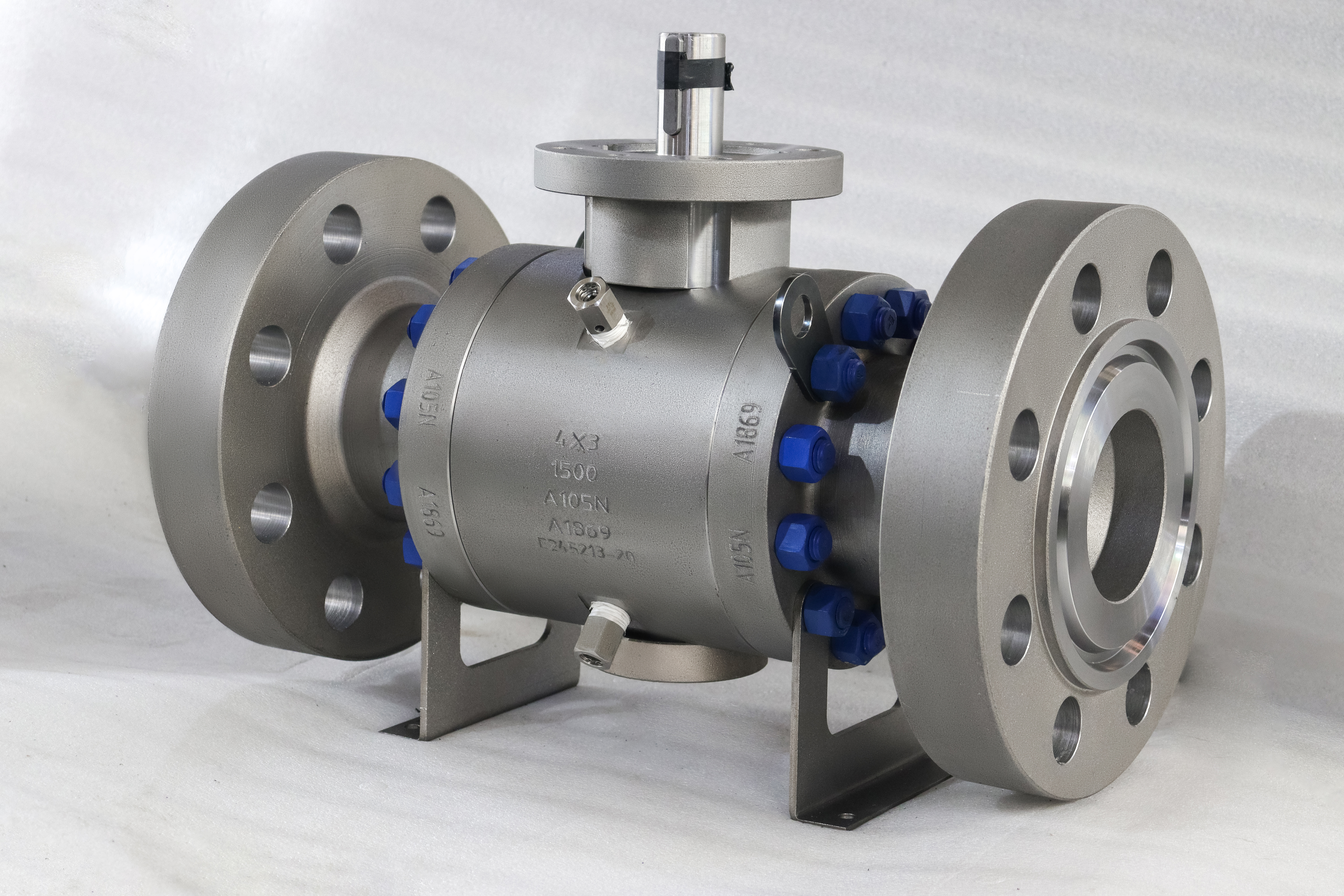
This is a four inch class 1500 forged A105N trunnion mounted ball valve with a three inch bore and a ring type joint flange. The marking 4x3 describes a DN100 flange around a DN80 bore, and the reduction is in the body rather than in the ball: the ball itself is a full port ball machined to DN80, so the flow path through the ball is a clean cylinder and the step is at the seat pockets.
That distinction matters when a buyer reads a photograph caption that says full bore. The valve is a reduced bore valve relative to the four inch line, and it is a full port ball relative to its own DN80 bore. Both statements are true and they describe different things, which is why the size on this page is written as two numbers with the flange and the bore named separately.
Design and Construction
The body is forged in two pieces and joined at one ring type joint flange. At Class 1500 that joint is the critical feature: the internal pressure tries to open it, the studs hold it closed, and the ring is confined in a groove so it cannot be extruded. A flat gasket at this class is pushed outward faster than the bolts can hold it, which is why the facing changes from raised face to ring joint at Class 900 and above.
The ball is carried on a trunnion at the bottom and driven by the stem at the top, with the seats spring loaded onto it from both sides. That means the valve seals in both directions, the seat load does not rise with line pressure, and the torque stays low enough for a lever at four inch Class 1500. The seats relieve if cavity pressure rises above line pressure, so no external cavity vent is fitted.

Material Options
A105N is a forged carbon steel with a controlled nitrogen addition for grain size, and it is the default body at this class because a forging carries the Class 1500 wall without the porosity risk of a casting. It is ultrasonic tested where ordered, on the billet rather than the finished body, because that is where a shrinkage defect would sit.
Where the medium is corrosive, the body moves to A182 F316 or F44, and the choice follows the chloride content and the temperature rather than the pressure. The trim moves with it: a hard chrome or ENP ball for clean service, stainless or duplex for abrasive or corrosive service, and a seat that runs from PTFE to a hardfaced metal seat depending on how hot the line actually gets.
| Component | Standard Material | Optional Upgrade | Service Notes |
|---|---|---|---|
| Main body | ASTM A105N forging | A182 F316 or F44 forging | Carries the trunnion bearing and the upstream seat |
| End cap | ASTM A105N forging | Same heat where required | Carries the downstream seat |
| Ball | A105N with ENP or hard chrome | Stainless or duplex ball | Full port through the ball at DN80 |
| Trunnion | Surface hardened A105N | 17-4PH | Takes the seat load on a bearing |
| Bearing | PTFE and graphite composite | Stainless backed bush | Keeps the torque manageable at Class 1500 |
| Stem | 17-4PH | A105N with ENP, 718 | Blowout proof, keyed to the ball |
| Stem extension | Carbon steel with a guide bush | Stainless extension | Moves the operator, not the packing |
| Seat | PTFE or RPTFE | PPL, PEEK, metal with graphite | Spring loaded, self relieving |
| Joint gasket | Ring type joint, metal | Soft iron or stainless ring by medium | Confined in the groove |
| Operator | Lever at the extension top | Worm gear or actuator | ISO 5211 pad at the extension top |
Technical Specifications
The two size numbers are the ones to read carefully. DN100 is the flange and DN80 is the bore, and a buyer who orders by the first number alone gets a valve that bolts up correctly and restricts the line. The pressure class fixes the wall, the flange, the shell test pressure and the ring joint facing together, and the face to face length follows ASME B16.10 on the drawing rather than a catalogue.
The extension length is the fourth number and it is a site dimension. It is measured from the body flange face to the top of the extension, set by the operating level or the insulation thickness, and it is not interchangeable between projects. A valve ordered without it arrives with a standard extension that fits nothing in particular.
| Item | Value |
|---|---|
| Product type | Forged steel trunnion mounted ball valve, reduced bore |
| Nominal size | 4 x 3 inch, DN100x80, a DN100 flange with a DN80 bore |
| Pressure class | Class 1500 (marked 1500LB), PN250 in the API 6D designation |
| Body material | ASTM A105N forged carbon steel |
| Body construction | Two piece forged body, one bolted joint |
| Ball support | Trunnion mounted, upper and lower bearing |
| Ball | A105N with ENP, hard chrome, or stainless on request |
| Bore through the ball | DN80 full port through the ball, the reduction is in the body |
| Stem | 17-4PH, A105N with ENP, or 718 where ordered |
| Trunnion | Surface hardened A105N, or 17-4PH |
| Stem extension | Length to the operating level or the insulation |
| Seat | PTFE to 150 C, RPTFE to 180 C |
| Seat option | PPL to 280 C, PEEK to 260 C, metal with graphite to 425 C |
| Seat design | Spring loaded, both seats independently energised |
| Cavity relief | Self relieving through the seat |
| Packing | Flexible graphite, or PTFE V rings for lower temperature |
| Body joint gasket | Ring type joint, confined in the groove |
| Bolting | A193 B7 with A194 2H, torque from the drawing |
| End connection | Flanged ring type joint, ASME B16.5 Class 1500 |
| End option | Butt weld ends to ASME B16.25 |
| Face to face | ASME B16.10, held on the drawing |
| Design standard | ASME B16.34, API 6D, API 608 |
| Test standard | API 598, API 6D |
| Fire safe | API 607 with the seat compound supplied |
| Anti static | Ball to body continuity, measured per valve |
| Temperature range | -29 to 425 C body, ceiling set by the seat |
| Media | High pressure gas, oil, water, process liquid |
| Operation | Lever at the extension top |
| Operation option | Worm gear, pneumatic or electric to ISO 5211 |
| Traceability | EN 10204 3.1 certificate with the heat number |
Standards and Compliance
The risk on a reduced bore valve at this class is not a missing standard, it is applying the right standard to the wrong number. API 6D and ASME B16.34 both key off the class and not off the bore, so a 4x3 valve is treated as a Class 1500 valve throughout: the wall, the flange, the shell test pressure and the ring groove all follow Class 1500 even though the flow path is DN80. Reading the standards off the bore instead of the class is how a body ends up under walled.
At Class 1500 the ring joint is a separate item with its own standard and its own material choice, and that is a compliance point rather than a detail. A soft iron ring in a corrosive medium is the wrong ring whatever the flange is made of, and the ring material belongs on the purchase order next to the body material.
| Requirement | Standard | What J-VALVES Supplies |
|---|---|---|
| Wall and rating | ASME B16.34 | Forged wall tabulated for Class 1500 in carbon steel |
| Pipeline design | API 6D | Cavity relief, documentation, marking |
| Ball valve specifics | API 608 | Anti static path, blowout proof stem, nameplate |
| Flange drilling and facing | ASME B16.5 Class 1500 | Ring type joint groove at this class |
| Face to face | ASME B16.10 | Length on the signed drawing |
| Pressure test | API 598 | Shell 1.5 times and seat 1.1 times the rating |
| Fire test | API 607 | Certificate against the seat compound |
| Joint gasket | ASME B16.20 | Ring material matched to the medium |
| Material certificate | EN 10204 3.1 | Heat number traced from the forging |
Manufacturing Process
The forging is normalised, then machined as a pair so the joint faces and the seat pockets come from the same setting. The ring groove is cut after the joint faces and checked with a profile gauge against ASME B16.20, because a groove a few hundredths deep will leak with a perfect ring and the error is invisible without a gauge.
The trunnion bore at the bottom of the body is cut in the same setting as the seat pockets, since a trunnion off centre by a few hundredths loads the bearing on one side and shows up as a heavy lever rather than as a leak. The extension is welded at its base and that weld is penetrant tested before the assembly is pressure tested.

Quality Control and Testing
The shell test is run with the joint torqued to the drawing figure, so that the test reflects the joint as it will be in service. At Class 1500 a joint that is going to weep does it on the bench, and a joint that is retorqued rather than reopened and refitted with a new ring is a leak waiting for the first thermal cycle.
The cavity relief check is specific to the trunnion design and runs before painting. Torque is measured at the rated pressure and issued with the drawing, because the difference between a comfortable lever and a two handed one at four inch Class 1500 is small and the actuator selection depends on the measured figure rather than a catalogue one.
| Step | What Is Checked | Standard or Acceptance |
|---|---|---|
| Chemistry | A105N carbon and manganese within range | Spectrographic analysis per heat |
| Forging soundness | Ultrasonic test of the body forging | UT per order, on the billet |
| Ring groove | Groove profile against ASME B16.20 | Gauged before assembly |
| Shell test | Body and joint at Class 1500 | 1.5 times the rating, held to API 598 |
| Seat test | Both directions | 1.1 times the rating, no visible leakage |
| Cavity relief | Seat lift at the designed differential | Checked on assembly, recorded |
| Torque | Breakaway torque at the rated pressure | Measured, issued with the drawing |
| Extension runout | Stem square over the extension length | Dial gauge at the top of the extension |
| Anti static | Ball to body continuity | Measured in ohms per valve |

Applications and Industry Service
The valve is used on high pressure gas lines, wellhead and injection skids, oil transfer at high pressure, and process isolation where a four inch flange is the pipe size and the flow does not need the full bore. The reduced bore is deliberate on most of those duties: the line is sized for a flow a DN80 bore can pass, and a full bore valve at Class 1500 would cost more and weigh more for no gain.
It is the wrong valve where the line will be pigged, because the bore step is a ledge a pig cannot pass. It is wrong where the medium carries chlorides at temperature, and it is wrong where the flow is already near the line capacity, since the reduction behaves like a short orifice rather than like a length of pipe.

Installation, Operation and Maintenance
The valve goes in with the end cap downstream and the ring correctly seated in its groove, studs lubricated, and the cross pattern done in three stages with a torque wrench. At Class 1500 the stud preload is high and an uneven pull distorts the joint face, and the leak appears at the first thermal cycle rather than at commissioning.
A seat change is a joint job: isolate, vent, drain, take the studs out, lift the end cap, and the downstream seat and ball are accessible. The ring and the seat O rings are replaced every time, and the groove is inspected for a dent before the new ring goes in. On an extended stem valve the extension is supported where it passes through the insulation rather than being held by it.
How to Specify and Order
An order needs the two size numbers stated separately, the class, the body and trim, the ring material, and the extension length if one is required. For this valve that is DN100 flange, DN80 bore, Class 1500, A105N, PTFE seat, ring type joint, and the extension dimension from the drawing.
Ask for the material certificate to EN 10204 3.1, the pressure test record, the ring groove inspection, the cavity relief check and the measured torque. Spares worth holding are a ring joint, a seat and O ring kit and a set of packing rings, and on a Class 1500 valve the ring is the cheapest item on that list and the one that stops a reassembly.
FAQ
Q: What does 4x3 mean on this valve?
A: The first number is the flange and the second is the bore. This valve bolts to a four inch line and passes a three inch bore, so it is a reduced bore design. The ball itself is a full port ball at DN80, which is why a caption can say full bore and still describe a reduced bore valve.
Q: Is Class 1500 the same as PN250?
A: Yes. API 6D clause 7.2 lists PN250 against Class 1500. The valve is marked with the class and flanged to ASME B16.5 Class 1500, which uses a ring type joint facing rather than a raised face.
Q: Why a ring type joint at this class?
A: Because a flat gasket is pushed outward by the internal pressure faster than the bolts can hold it at Class 1500. The ring is confined in a machined groove so it has nowhere to extrude to, and the seal is metal to metal rather than a compressed sheet.
Q: Can the ring joint be reused?
A: No. The ring takes a set when it is compressed, so a reused ring leaks. It is a consumable and belongs on the spares list, and the groove is inspected for damage every time the joint is opened because a dented groove will leak with a new ring as well.
Q: Why is the stem extended?
A: To put the operator at a reachable level, or outside an insulation jacket. The packing stays in the body, so the extension moves the operator rather than the seal, and a weeping gland remains a body job rather than something adjusted at the top of the extension.
Q: Does this valve need a cavity relief vent?
A: No. The seats are self relieving, so pressure trapped in the body cavity lifts a seat and escapes to the low pressure side. That is how the API 6D cavity relief requirement is met on this design and the relief direction is marked on the body.


Hot Products


News
Ball Valves in A Kraft Pulp Mill: Black Liquor, Green Liquor And The Cost of Choosing The Alloy by Habit
White liquor at pH 14 cracks carbon steel welds, black liquor sets solid below 100 C, green liquor dregs grind seats: alloy choice and torque in a kraft mill.
Read More
Slug Flow And Ball Valves: What Actually Arrives At The Seat
A slug is liquid mass with momentum, not a pressure spike. What changes at the seat, in the cavity and at the actuator when liquid reaches a ball valve.
Read More
Ball Valves in Direct Lithium Extraction: PH 1 Eluate, Gypsum Scale And 438,000 Cycles in Twenty-Five Years
Direct lithium extraction swings valves from pH 1 eluate to pH 12 caustic, 48 column switches a day and gypsum scale. Materials, seats and torque.
Read More
Ball Valves in Geothermal Brine: Silica Scale, Chloride Cracking And The Cooling Trap
Why geothermal brine destroys ball valves: retrograde silica scale, calcite at the flash point, chloride cracking above 60 C and the 250 C seat limit.
Read More