


CHINA J-VALVES Offers Various High-quality I ndustrial Ball Valves
J-VALVES, a distinguished professional ball valve manufacturer rooted in China, takes pride in its extensive product portfolio. Our offerings span a wide range, including trunnion-mounted ball valves, floating ball valves, high-temperature ball valves, high-pressure ball valves, metal-sealed ball valves, ultra-low temperature ball valves, DBB ball valves, Three-way And Four-way Ball Valve, and fully welded ball valves. Each product is a testament to our commitment to precision engineering and reliable performance. Meticulously crafted, they are designed to not only meet but exceed the most stringent industrial demands, ensuring stable operation even under extreme conditions. This enables us to provide our clients with high-value services and makes our valves widely sought-after in industries.
Product Category
Contact Us


-
J-VALVES-Q347F
-
J-VALVES
Overview of the J-VALVES 6x4 Inch Reduced Bore Trunnion Ball Valve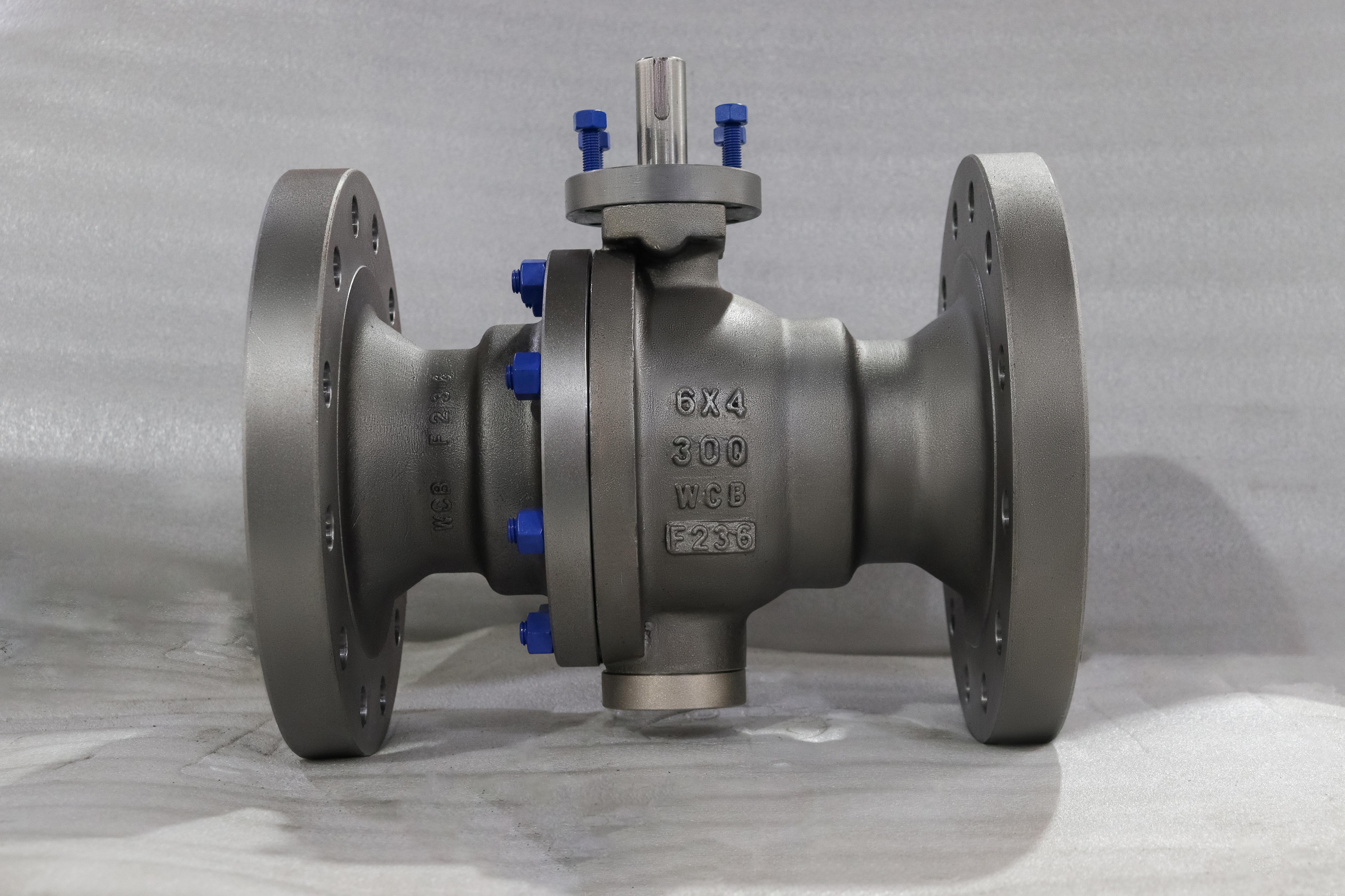
This valve bolts to a six inch Class 300 flange and passes a four inch bore. The two numbers are not a mistake and they are not two end sizes: DN150 is the flange, DN100 is the bore, and the reduction is chosen on purpose. The body is cast WCB, the ball is carried on a trunnion rather than floating, and the seats are spring loaded and self relieving.
The trunnion is the structural decision that makes the size possible. On a floating valve the ball is pushed onto the downstream seat by the line pressure, and at six inch that force is large enough to make the valve hard to turn and to wear the seat ring. A trunnion takes that load on a bearing at the bottom of the body, so the ball only rotates and the seat load is set by springs rather than by the pressure in the line.
Design and Construction
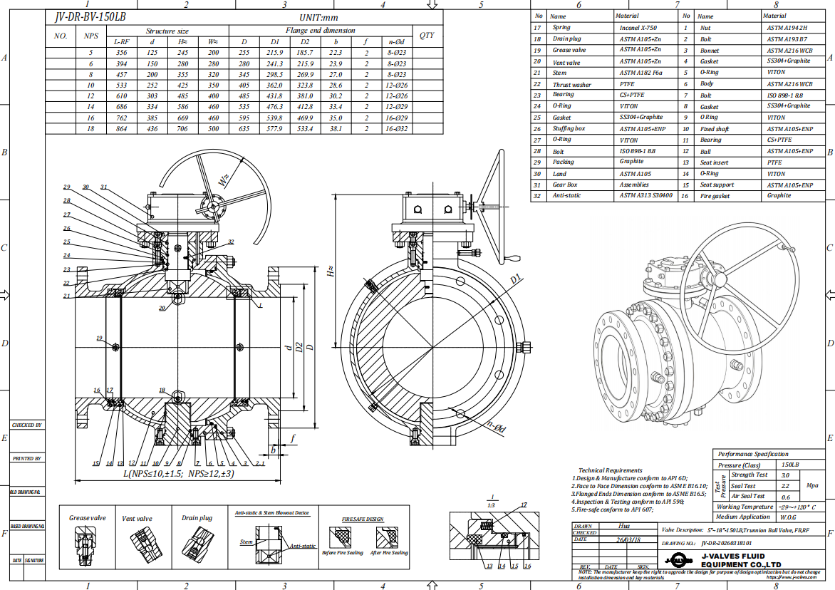
The body splits at one joint with the end cap downstream, which puts the joint on the low pressure side while the valve is closed. The ball is trapped between the two seat rings and is located by a trunnion at the bottom and the stem at the top, so it cannot move axially by more than the clearance in the bearings. That is the opposite of the floating design, where the axial movement is what creates the seal.
Each seat is pushed against the ball by a ring of springs, so both seats seal independently and the valve is bidirectional in the engineering sense rather than only in the marketing sense. The seat also relieves: if pressure trapped in the body cavity rises above the line pressure, the seat lifts and lets it out. That is why a trunnion valve of this design does not need an external cavity vent, and why the relief direction is marked on the body.
Material Options
WCB is the right body for water, oil and gas at Class 300, and the material code F236 stamped on the body is a catalogue reference rather than a standard grade. The standard grade is ASTM A216 WCB and that is what the certificate reports; a buyer checking the stamp against an ASTM table will not find F236 there, and should read it as the maker internal code alongside the A216 marking.
The ball and trunnion take the wear, so they are the parts worth upgrading. A hard chrome plated ball is standard; a 316 ball is specified where the medium carries fine solids; the trunnion runs in a PTFE and graphite composite bush that keeps the torque low without grease. The seat compound sets the temperature ceiling, and on a reduced bore valve the seat is smaller than the flange, which is one of the reasons the valve runs cooler than a full bore unit at the same class.
| Component | Standard Material | Optional Upgrade | Service Notes |
|---|---|---|---|
| Main body | ASTM A216 WCB | Impact tested WCB for low temperature | Carries the trunnion bearing at the bottom |
| End cap | ASTM A216 WCB | Same heat where required | Closes the downstream seat |
| Ball | A105N or WCB, hard chrome | 316 stainless | Held on the trunnion, does not move with pressure |
| Trunnion | Surface hardened carbon steel | 17-4PH | Carries the seat load instead of the seat ring |
| Bearing | PTFE and graphite composite | Stainless backed bush | Low friction at high seat load |
| Stem | 17-4PH | 316 with ENP | Blowout proof, keyed to the ball |
| Seat | PTFE or RPTFE | PPL, nylon, hardfaced metal | Spring loaded, independently energised |
| Packing | PTFE V rings | Flexible graphite | Adjustable at the gland |
| Joint gasket | Spiral wound, graphite filler | PTFE envelope for clean service | Single use item |
| Operator | Lever | Worm gear, actuator | Gear is the practical choice above 8 inch |
Technical Specifications
The bore ratio is the number to think about before ordering. A DN100 bore in a DN150 line adds a contraction and an expansion, and the pressure drop across that pair is not trivial at high flow: the valve behaves like a short orifice rather than like a piece of pipe. On a line sized with margin, that is acceptable and the saving on valve cost and actuator torque is real. On a line already running near its limit, the reduced bore is where the flow goes missing.
Everything else follows the class. Class 300 fixes the wall to ASME B16.34, the flange to ASME B16.5, the shell test at one and a half times the rating and the seat test at one and a time the rating. The face to face length follows ASME B16.10 and is held on the drawing. The table below is what the valve is built and tested against, and the bore column is the one that separates this product from a full bore valve of the same size and class.
| Item | Value |
|---|---|
| Product type | Two piece flanged trunnion mounted ball valve, reduced bore |
| Nominal size | 6 x 4 inch, DN150x100, a DN150 flange with a DN100 bore |
| Pressure class | Class 300 (marked 300LB), PN50 in the API 6D designation |
| Body material | ASTM A216 WCB cast carbon steel |
| Material code | F236 as stamped, a catalogue code rather than a standard grade |
| Body construction | Two piece, one bolted joint |
| Ball support | Trunnion mounted, upper and lower bearing, not floating |
| Ball | A105N or WCB, hard chrome plated, or 316 stainless |
| Stem | 17-4PH precipitation hardening stainless |
| Trunnion | Surface hardened or 17-4PH, with a self lubricating bearing |
| Seat | PTFE, RPTFE, PPL, nylon, or a hardfaced metal seat |
| Seat design | Spring loaded, both seats independently energised |
| Cavity relief | Self relieving through the seat, no external vent |
| Packing | PTFE V rings, flexible graphite option |
| Body joint gasket | Spiral wound with graphite filler |
| End connection | Flanged raised face or ring type joint, ASME B16.5 Class 300 |
| Face to face | ASME B16.10, held on the drawing |
| Bore ratio | DN100 bore in a DN150 line, a deliberate reduction |
| Design standard | ASME B16.34, API 6D, API 608 |
| Test standard | API 598, API 6D |
| Temperature range | -29 to 425 C body, ceiling set by the seat |
| Fire safe | API 607 with the seat compound supplied |
| Anti static | Ball to body continuity, measured per valve |
| Operation | Lever at this size, worm gear from 8 inch upward |
| Operation option | Pneumatic or electric actuator to ISO 5211 |
| Mounting | ISO 5211 pad on the neck |
| Media | Water, oil, gas, slurry free process lines |
| Marking | Size, class, material and heat number on the body |
| Traceability | EN 10204 3.1 certificate with the heat number |
| Pressure code note | PN50 is the API 6D code for Class 300 |
Standards and Compliance
Both API 6D and API 608 apply to this valve and they are not alternatives. API 6D is the pipeline valve standard and it governs the trunnion design, the cavity relief requirement and the documentation that a pipeline operator expects. API 608 covers the ball valve specifics that apply regardless: anti static path, blowout proof stem, nameplate content. An order should name both where the line is a pipeline and only API 608 where it is plant piping.
ASME B16.34 supplies the wall and the rating, ASME B16.5 the flange, ASME B16.10 the length, and API 598 the test. Fire safe performance is certified to API 607, and on this valve it rests on the metal seat shoulder and the graphite joint gasket rather than on the soft seat. The cavity relief requirement in API 6D is the one that buyers most often do not know to ask about, and it is the reason a trunnion valve does not need an external vent on the body.
| Requirement | Standard | What J-VALVES Supplies |
|---|---|---|
| Wall and rating | ASME B16.34 | Cast wall tabulated for Class 300 in carbon steel |
| Valve design | API 6D and API 608 | Both apply: pipeline design and floating or trunnion details |
| Flange drilling | ASME B16.5 Class 300 | Raised face or ring type joint, pattern by size |
| Face to face | ASME B16.10 | Length on the signed drawing |
| Pressure test | API 598 | Shell 1.5 times and seat 1.1 times the rating |
| Fire test | API 607 | Certificate against the seat compound |
| Cavity relief | API 6D requirement | Self relieving seat, direction marked on the body |
| Material certificate | EN 10204 3.1 | Heat number traced from the casting |
| Actuator interface | ISO 5211 | Pad and drive size stated on the drawing |
Manufacturing Process
The castings are normalised before machining, then machined as a pair so the bore and the seat pockets line up when the joint is closed. The trunnion bore at the bottom of the body is machined in the same setting as the seat pockets, because a trunnion that is off centre by a few hundredths loads the bearing on one side and shows up later as a stiff valve rather than as a leak.
The flange is drilled last from the ASME B16.5 table for Class 300 at the size ordered. On a reduced bore valve the flange is the large end and the bore is the small one, so the two operations are independent and a mistake in either is a valve that does not fit. The body is then blasted and coated with the flange face masked, since coating under a gasket is a leak waiting for a thermal cycle.

Quality Control and Testing
Testing runs shell, then seat in both directions, then cavity relief. The relief check is specific to this design: the body cavity is pressurised with the valve closed and the seat is watched for lifting at the designed differential. A valve that passes the seat test and fails the relief check will trap pressure in the cavity and can split the body on a thermal cycle, which is a failure mode that does not appear on a floating valve at all.
Torque is measured on the assembled valve at the rated pressure and issued with the drawing, because the actuator selection depends on it and a guessed figure is how a gearbox ends up undersized. Anti static continuity is measured from the ball to the body flange on every valve. The bore is checked for roundness at both seat pockets, since a reduced bore valve has a step in it and a poorly blended step is a place where solids collect.
| Step | What Is Checked | Standard or Acceptance |
|---|---|---|
| Chemistry | WCB range, carbon and manganese | Spectrographic analysis per heat |
| Casting | Porosity at the joint face and seat pockets | Visual and penetrant, radiography on request |
| Bore concentricity | DN100 bore centred in the DN150 flange | Measured from the flange face |
| Flange drilling | Bolt circle and facing against ASME B16.5 | Gauged, recorded per valve |
| Shell test | Body and joint under pressure | 1.5 times the rating, held to API 598 |
| Seat test | Both directions, both seats | 1.1 times the rating, no visible leakage |
| Trunnion torque | Breakaway torque at the rated pressure | Measured, issued with the drawing |
| Anti static | Ball to body continuity | Measured in ohms per valve |
| Cavity relief | Seat relief direction against the marking | Checked on assembly, recorded |

Applications and Industry Service
The valve is used on plant water, cooling water, oil transfer, gas gathering and general process isolation where the line is six inch and the flow does not need the full bore. Reduced bore is common on lines that were sized with margin, and on those it saves both valve cost and actuator cost without changing the pipe. It is also common where the valve is a block valve rather than a control element, so the pressure drop is paid once and not modulated.
It is the wrong choice on a line that will be pigged, because the bore step is a ledge that a pig cannot pass cleanly. It is wrong where the flow is already near the line capacity, and it is wrong where a full bore is a contractual requirement for the pipeline operator. Those are specification decisions rather than product faults, and they should be settled before the valve is ordered rather than after the flow test.

Installation, Operation and Maintenance
The valve goes in with the end cap downstream and the cavity relief direction matching the marked flow arrow. Bolts are drawn up in a cross pattern in stages, and on a six inch Class 300 flange that means a torque wrench rather than a spanner, because the pattern is long enough that an uneven pull distorts the gasket. The valve is not a pipe support and should not be used to close a gap between two flanges.
A seat change is a joint job: isolate, vent, drain, take the studs out, lift the end cap, and the downstream seat and ball are accessible. The upstream seat needs the ball out, which means the valve comes off the line. The joint gasket and the seat O rings are replaced as a matter of course, and the trunnion bearing is inspected at the same time, because a worn bearing shows up as high torque long before it shows up as a leak.
How to Specify and Order
An order needs the two size numbers stated separately, the class, the body and trim, the flange facing and the bore. For this valve that is DN150 flange, DN100 bore, Class 300, WCB, PTFE seat, raised face. If the valve replaces an existing reduced bore unit, the installed face to face length and the bore should be measured rather than assumed from the size, because reduced bore valves of the same nominal size can differ in both.
Ask for the material certificate to EN 10204 3.1, the pressure test record, the cavity relief check record and the measured torque. Where an actuator or a gearbox is fitted, the torque figure is what the actuator is sized against and it should be the measured figure rather than a catalogue value. Spares worth holding are a seat and O ring kit and a joint gasket, which cover the two items that stop the valve working.
FAQ
Q: What does 6x4 mean on a ball valve?
A: The first number is the flange size and the second is the bore. This valve bolts to a six inch line and passes a four inch bore, so it is a reduced bore design. The two numbers are not two end sizes, and a buyer who reads them that way will expect a reducer that is not part of the valve.
Q: Why use a trunnion instead of a floating ball at this size?
A: Because the seat load on a floating ball grows with the pressure and the area, and at six inch Class 300 that load makes the valve hard to turn and wears the seat ring. A trunnion carries the load on a bearing at the bottom of the body, so the ball only rotates and the seat load is set by springs.
Q: How much pressure drop does a reduced bore add?
A: It behaves like a short orifice rather than like a length of pipe, so the drop depends on the flow and the fluid rather than on the valve alone. On a line sized with margin it is acceptable; on a line already running near capacity it is where the flow goes missing. The drop should be calculated for the actual duty rather than assumed small.
Q: Does this valve need a cavity relief vent?
A: No. The seats are self relieving, so pressure trapped in the body cavity lifts the seat and escapes to the low pressure side. That is an API 6D requirement for this design, and the relief direction is marked on the body. A floating ball valve has no cavity to relieve in the same way.
Q: Is the body material F236 a standard grade?
A: No. F236 is a catalogue code stamped alongside the standard marking. The body is ASTM A216 WCB, which is what the material certificate reports. A buyer checking F236 against an ASTM table will not find it, and should read it as the maker internal reference rather than as a grade.
Q: Can a reduced bore valve be pigged?
A: Not cleanly. The step from the DN150 flange down to the DN100 bore is a ledge, and a pig cannot pass it without damage to the pig or to the seat. Where the line will be pigged, a full bore valve or a different valve type is the right product.


Hot Products


News
Ball Valves in A Kraft Pulp Mill: Black Liquor, Green Liquor And The Cost of Choosing The Alloy by Habit
White liquor at pH 14 cracks carbon steel welds, black liquor sets solid below 100 C, green liquor dregs grind seats: alloy choice and torque in a kraft mill.
Read More
Slug Flow And Ball Valves: What Actually Arrives At The Seat
A slug is liquid mass with momentum, not a pressure spike. What changes at the seat, in the cavity and at the actuator when liquid reaches a ball valve.
Read More
Ball Valves in Direct Lithium Extraction: PH 1 Eluate, Gypsum Scale And 438,000 Cycles in Twenty-Five Years
Direct lithium extraction swings valves from pH 1 eluate to pH 12 caustic, 48 column switches a day and gypsum scale. Materials, seats and torque.
Read More
Ball Valves in Geothermal Brine: Silica Scale, Chloride Cracking And The Cooling Trap
Why geothermal brine destroys ball valves: retrograde silica scale, calcite at the flash point, chloride cracking above 60 C and the 250 C seat limit.
Read More