


CHINA J-VALVES Offers Various High-quality I ndustrial Ball Valves
J-VALVES, a distinguished professional ball valve manufacturer rooted in China, takes pride in its extensive product portfolio. Our offerings span a wide range, including trunnion-mounted ball valves, floating ball valves, high-temperature ball valves, high-pressure ball valves, metal-sealed ball valves, ultra-low temperature ball valves, DBB ball valves, Three-way And Four-way Ball Valve, and fully welded ball valves. Each product is a testament to our commitment to precision engineering and reliable performance. Meticulously crafted, they are designed to not only meet but exceed the most stringent industrial demands, ensuring stable operation even under extreme conditions. This enables us to provide our clients with high-value services and makes our valves widely sought-after in industries.
Product Category
Contact Us


-
J-VALVES-Q47F
-
J-VALVES
Overview of the J-VALVES Six Inch PN150 Forged F316 Three Piece Trunnion Ball Valve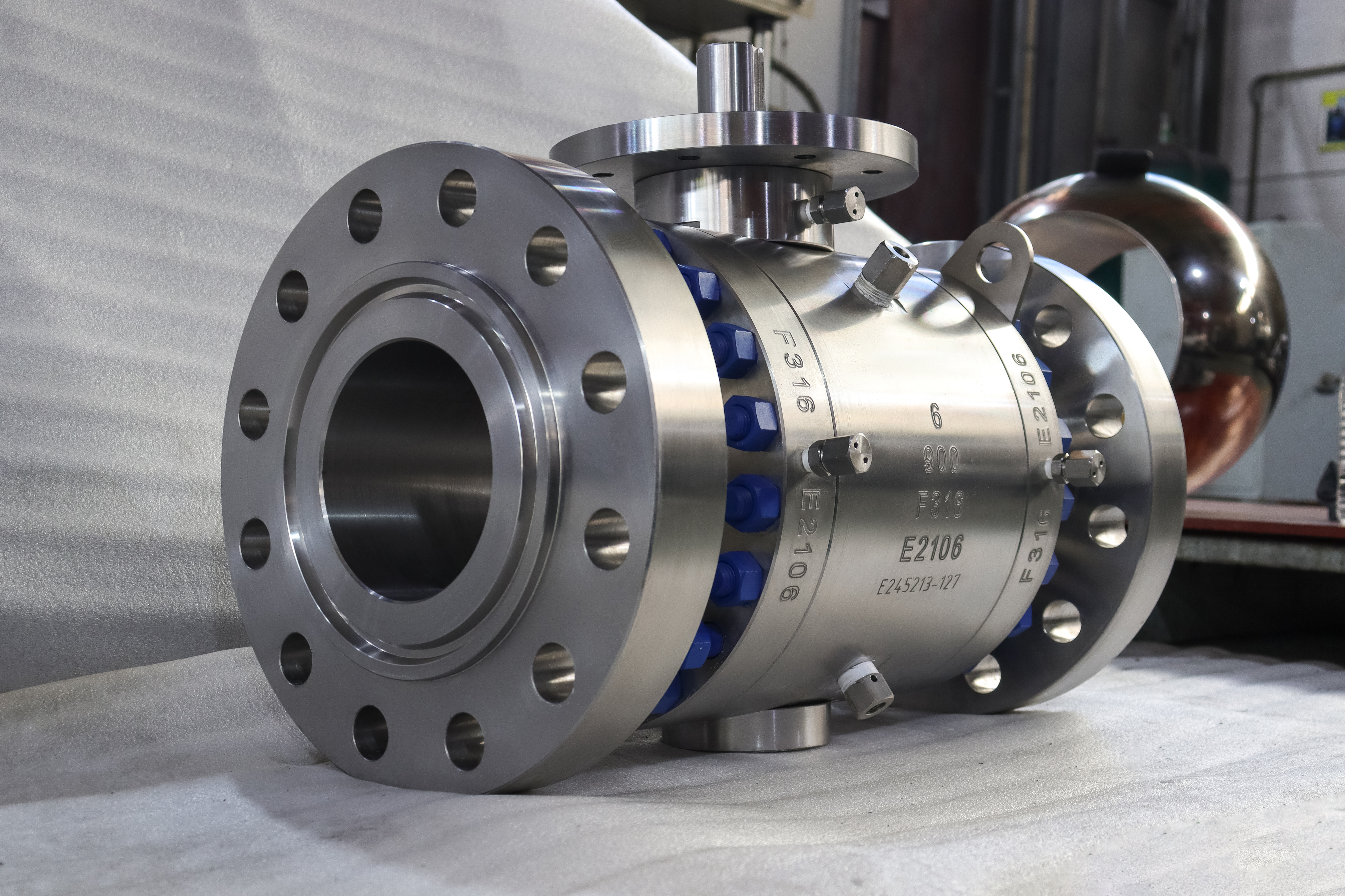
This is a three piece trunnion mounted ball valve in forged A182 F316, six inch at Class 900, with flanged ends and a bare stem on a machined mounting pad. The body reads six over 900 over F316 over the works number, and both end caps repeat F316 and the same works number, so every pressure containing part in the valve is one grade from one heat. Class 900 is the first class in this catalogue where the product standard runs out. API 608 covers flanged valves to Class 600 and threaded valves to Class 800, so a 900 class valve cannot be certified to it at any size.
What governs instead is API 6D plus ASME B16.34, and that changes which documents a buyer should be asking for. The detail that decides whether this valve can be installed and maintained is not on the datasheet. It is the trunnion cover on the underside of the body, which is a pressure boundary item reached from below. A valve of this size on a pipe rack with no clearance underneath is a valve whose lower bearing cannot be inspected for the life of the plant.
Class 900 at six inch is almost always the class written in the piping specification rather than a pressure the line actually reaches. That matters for the order, because it means the flange, the face to face and the wall are fixed by the specification and only the trim is really open to choice. It also means the valve will be judged on what a specification cannot fix: whether the seats hold after a thermal cycle, whether the body joints stay tight, and whether the bottom cover can be reached by a fitter standing on a grating.
Design and Construction
Three pieces means a centre body and two end caps, with two bolted body joints and two gaskets. The ball, both seats and both trunnion bearings live in the centre section and stay there when the caps come off, which is the structural reason the two bearing bores can be machined in one setup and keep their alignment for the life of the valve. The upper trunnion is the driven shaft and the lower trunnion is a locating shaft. The lower one runs in a bearing housed in the cover bolted to the bottom of the body, which makes that cover the third pressure boundary opening after the two end caps, and the only one that faces the ground.
It also sits near the lowest point of the cavity, which is why the cavity drain is normally found close to it. The top of the valve is a machined pad with four bolt holes and a bare stem, with no lever and no gearbox. That is deliberate: at this class the operator is a decision rather than an accessory, and the pad is the interface that decision bolts onto. Below it sits a bolted gland, so stem packing can be serviced with the line under pressure once the cavity is vented.
Two body joints mean twice the bolting, and bolting is the part that changes after the first hot cycle. A stud that was correct at assembly relaxes when the joint heats and cools, and on a valve that sees temperature swings the answer is a documented hot re-torque rather than a hope. That is a maintenance instruction rather than a defect, and it belongs in the handover pack beside the torque figures. A three piece valve that has never been re-torqued has not proved anything; it simply has not been hot yet.

Material Options
Forging is the default across the whole pressure boundary here, not only the body. That is worth stating because the end caps are the parts most often downgraded to castings on a quote, and on this valve they carry the same stamp as the body. The seat is the field that arrives blank on most quotes and should never be left blank. At Class 900 a metal seat is the normal answer, and a metal seat carries a permitted leakage rate rather than a bubble tight claim. If a soft insert is ordered to get zero visible leakage, it is the temperature that has to be traded, not the pressure.
The stem is the one part where the standard and the service can disagree. 17-4PH is strong and does the job in clean service, but NACE MR0175 caps its hardness, and above that cap the answer is a different alloy rather than a harder one. Sour service belongs in the enquiry, not in the file afterwards. The trunnion bearings are the parts nobody asks about and everybody depends on. The lower shaft runs in a bearing inside the bottom cover, and that bearing carries the ball load while letting the shaft turn freely; if it is dry, tight or contaminated the symptom is a valve that needs more torque than the actuator was sized for.
Grease access through the bottom cover is therefore a maintenance feature rather than a detail, and a cover with no provision for it turns a bearing inspection into a body strip. Coating thickness on the ball is a wear allowance rather than a finish, and the number in the order should be the one the supplier can measure. A thin coating wears through at the seat contact band and leaves a carbon steel or stainless ball running against a polymer seat with a hard edge; a thick one can crack at the edge of the band. Neither failure is visible from outside, which is why the coating specification belongs on the purchase order next to the ball grade rather than in a general note about surface treatment.
| Component | Standard Material | Optional Upgrade | Service Notes |
|---|---|---|---|
| Body and end caps | ASTM A182 F316 forging | F316L where welded fabrication is planned | Both caps stamped F316 with the body works number |
| Ball | F316 with ENP or hard chrome | Tungsten carbide HVOF or cobalt based hard facing | Ball grade to the 3.1 certificate, not to the photograph |
| Stem | 17-4PH precipitation hardening | F316 with ENP, or nickel based alloy | Hardness limit applies in sour service under NACE MR0175 |
| Trunnion shafts | Surface hardened F316 or 17-4PH | Nickel based alloy for high temperature | Lower shaft runs in the bearing in the bottom cover |
| Seat | Metal seat as ordered | Soft insert seat for lower classes only | Seat choice sets the leakage class, not the body |
| Packing | Flexible graphite with wire reinforcement | PTFE for lower temperature duty | In the gland at the top of the neck |
| Gasket | Spiral wound, flexible graphite filled | Ring joint gasket for RTJ faces | Two joints, one per end cap |
| Bolting | A193 B8M with A194 8M nuts | B7 with 2H nuts for non corrosive duty | B7 on a stainless body is the weak point of the joint |
Technical Specifications
The rows below follow the stamping and the standard tables. Ratings are read from the material group of this body rather than from the carbon steel row, because the two differ at every class. Two entries deserve a note. The rating is a table lookup in group 3.1, and group 3.1 sits below the carbon steel row at every class, so nobody should carry a carbon steel figure across to this valve and call it conservative. And the bore is a minimum rather than a match to pipe, so a full bore valve being slightly smaller than the pipe inside diameter is correct rather than a defect.
A metal seat is a different promise rather than a harder version of a soft seat. The soft seat is accepted on the basis of no visible leakage; the metal seat is accepted against a permitted rate, measured in a defined way, because metal on metal cannot conform the way a polymer does. Writing that difference into the specification is what stops the argument at commissioning, when a metal seated valve is found to pass a few bubbles and somebody compares it with the soft seated valve on the next line.
One row needs reading twice, because the two numbers on it are not the same kind of thing. Class 900 is the ASME class and PN 150 is the designation API 6D clause 7.2 writes against it, so neither is a pressure in bar. PN 150 is also not an EN 1092-1 nominal pressure: that series steps from PN 100 to PN 160, so a valve described as PN 150 cannot be built with European flanges under that name.
| Item | Value |
|---|---|
| Type | Three piece trunnion mounted ball valve, side entry |
| Nominal size | 6 inch, DN150 |
| Pressure class | Class 900, stamped 900 on the body |
| Pressure designation | PN 150, the designation API 6D clause 7.2 writes against Class 900 |
| Shell rating | ASME B16.34 group 3.1 at Class 900, read at design temperature |
| Body material | ASTM A182 F316 forging, caps stamped with the same works number |
| Bore | Full bore to API 6D Table 1 for NPS 6 |
| End connection | Raised face or ring joint flanged to ASME B16.5 |
| Alternative ends | Butt weld to ASME B16.25 |
| Face to face | ASME B16.10 for the size and class ordered |
| Trunnion | Upper driven shaft, lower locating shaft in a bolted bottom cover |
| Operator interface | Bare stem on a machined mounting pad, four bolt holes |
| Temperature, body | Group 3.1 range, flanged rating listed to 538 C |
| Temperature, valve | Set by the seat and the packing ordered |
| Product standard | API 6D, with ASME B16.34 for the pressure boundary |
| Test standard | API 598 and API 6D |
| Fire test | API 607 and ISO 10497 when specified |
| Anti static | Ball to stem to body, 10 ohm or less |
Standards and Compliance
The compliance table is where this page differs most from the low pressure ones. API 608 is absent by scope, not by choice, and the fire and sour service qualifications are separate documents rather than clauses of the product standard. Buyers sometimes ask for API 608 on a 900 class valve because it is the standard they know from small floating valves. The honest answer is that no supplier can issue that certificate, and a page that lists API 608 next to API 6D on a Class 900 valve is telling the buyer that the author did not check the scope.
The two test standards in the table are not a duplication. API 598 fixes the method and the acceptance; API 6D adds the requirements that come from the pipeline duty, including the pressure and duration schedule the purchaser may specify. Where both are quoted, the stricter of the two applies, which is a reason to name both in the order rather than to choose between them. Cavity relief is the point that separates a valve that survives from one that lifts a seat.
On a double piston effect seat the cavity cannot relieve itself, so trapped liquid that warms up has nowhere to go and will either lift a seat or load the body joint. The answer is a relief path or a change to a single piston seat, and it has to be decided when the seat arrangement is chosen rather than after the first warm shutdown. A page that offers piston seats without saying this has left out the only part that costs money.
| Requirement | Standard | What J-VALVES Supplies |
|---|---|---|
| Pressure boundary design | ASME B16.34 | Wall thickness and material group on the drawing |
| Product standard | API 6D | Design, marking and documentation to the pipeline valve standard |
| Product standard, note | API 608 does not apply | It covers flanged valves to Class 600 only, this valve is Class 900 |
| Pressure testing | API 598 and API 6D | Shell at 1.5 times rating, seat at 1.1 times rating |
| Fire qualification | API 607 and ISO 10497 | Certificate covering the size and class band ordered |
| Flange drilling | ASME B16.5 | Raised face or ring joint, Class 900, per the order |
| Face to face | ASME B16.10 | Length per the table for the size and class |
| Material certification | EN 10204 3.1 | Heat numbers on body and both caps, grade on the certificate |
| Sour service | NACE MR0175 | Hardness controlled parts listed on request |
Manufacturing Process
The centre body and the caps are forged, normalised and solution annealed, then machined. The two bearing bores are machined in the centre body in one setup, so the trunnion axes are coaxial by manufacture rather than by assembly. The caps are machined separately and only have to hold the seats and close the joint, which is what keeps the alignment stable after a rebuild. The bottom cover is machined as a separate pressure part with its own gasket and its own bolt circle.
It is a small part with a large consequence: the lower trunnion locates in it, so its bore position and squareness to the body axis decide how the ball sits between the seats. On assembly it is fitted and checked before the caps go on. Assembly ends with a full quarter turn under pressure and a check that the ball does not lift off the lower bearing. A trunnion valve that lifts will pass a seat test cold and leak after a thermal cycle, because the seat load depends on the ball staying where the shafts put it.
The sequence on a forged body is a sequence of removals, and the order of removal is what protects the geometry. Rough machine with allowance, stress relieve, then finish cut, so that most of the movement the forging makes when metal comes off it has happened before the faces that matter are finished. The centre body is then machined in one setup for both body joints and both trunnion bores, because that single setup is what puts the ball axis square to the joints. The shell test follows assembly and precedes the operator package.

Quality Control and Testing
Testing follows the standard sequence, with two additions that this design needs: the bottom cover is proved as a pressure part in its own right, and the trunnion axes are checked for alignment rather than assumed from the machining. Alloy verification is worth a sentence because it is often misunderstood. A portable analyser confirms the alloy family and catches a wrong grade, but it cannot see carbon, so it cannot separate F316 from F316L, and it cannot tell a forging from a casting.
Those answers come from the mill certificate and from the product form stated on it. The inspection pack on a Class 900 valve is worth listing because it is what the buyer actually keeps. The 3.1 certificate with heat numbers matching the stamping on the body and both caps. The shell and seat record, with the bottom cover included in the shell test rather than tested separately. The dimensional record for the facing, the bolt circle and the face to face. And, where sour service is in scope, the hardness results for the stem and the bolting.
Four documents, and a valve without them has to be re-verified on arrival. If a third party inspector is in scope, the inspection plan should name the two steps worth witnessing rather than the two that are easy to attend. The shell test on the bottom cover is one, because that cover is a pressure part and it is buried once the valve is assembled. The trunnion alignment check is the other, because the machining that produced it cannot be inspected afterwards.
| Step | What Is Checked | Standard or Acceptance |
|---|---|---|
| 1 Incoming material | Grade, product form, heat identity on body and caps | A182 F316 forging, certificate matches the stamping |
| 2 Dimensional | Bore, end to end, joint faces, pad and stem height | Drawing and ASME B16.10 for the size and class |
| 3 Bearing alignment | Coaxiality of upper and lower trunnion bores | In house tolerance on the signed drawing |
| 4 Bottom cover fit | Bore position, squareness, gasket seating | Cover fitted and checked before the caps are closed |
| 5 Shell test | Body, two body joints and the bottom cover | API 598, 1.5 times rating, no leakage |
| 6 Seat test | Both seats, both directions, at rated pressure | API 598, 1.1 times rating, acceptance per seat type |
| 7 Operating test | Quarter turn under pressure, no ball lift | Full travel, gland tight, no binding at either stop |
| 8 Records | Stamping, heat traceability, test and material sheets | Certificate and test record issued with the valve |

Applications and Industry Service
Six inch Class 900 sits in the band where a floating ball valve stops being sensible and a trunnion becomes the default. The seat load grows with the square of the bore, so the same pressure that is comfortable on a one inch valve becomes a handle problem at six inches. This is the size where the shaft takes the load and the seats only have to seal. Typical duty is high pressure isolation on gas, produced water, hydrate inhibited lines, chemical injection and high pressure process headers, anywhere the valve has to hold a differential and be operated by hand or by an actuator without a fight. The forged pressure boundary is chosen for soundness on a thick section rather than for corrosion resistance.
What it does not do is worth one line each. It is an isolation valve, not a control valve, and throttling on a metal seat will damage the seating surfaces. It does not belong underground without a stem extension and a valve box. And it should not be ordered for a line that needs double isolation with a verified barrier unless the seat type has been selected for that specific test. The duties that suit this valve are the ones where isolation has to be certain and the line runs for years between shutdowns: high pressure gas letdown, chemical injection, separator and header isolation, and the block valves either side of a metering run. What those have in common is that the valve is open or closed and rarely in between.
The duty it is not built for is throttling, and the second is anything where a soft seat would do the job for less money, because a metal seat is bought for temperature and for certainty rather than for tightness. Sour service changes the answer from a material to a hardness. NACE MR0175 does not ban a grade, it caps the hardness at which that grade can be used, and above the cap the answer is a different alloy rather than a harder one. That is why a stem question in a sour line is answered with a certificate and a hardness reading rather than with a catalogue page, and why sour service belongs in the enquiry rather than in a note added after the order has been placed and the bar cut.

Installation, Operation and Maintenance
The first installation decision is clearance under the body. The lower trunnion cover has to come off for bearing inspection, and it needs room to be withdrawn and room for a wrench. Set the valve on its feet or on a support under the body, never hang a six inch 900 class valve on its flange bolts alone, and leave the clearance in the piping layout rather than discovering it at commissioning. Orientation is stem up or stem horizontal, with the actuator or handle accessible and the pad clear. Support the body before tightening the flange bolts, not after; the reverse order puts bending into the body joints. On insulated lines, keep the gland and the mounting pad outside the lagging. Maintenance splits into two very different jobs.
Above the body, the stem packing can be adjusted or renewed with the line under pressure once the cavity is vented, because the stem is captive in the body. Below the body, nothing can be done under pressure: the bottom cover is a pressure boundary part and the valve must be isolated, vented and drained before it is touched. There are two installation facts that decide whether the valve can be maintained. The first is clearance under the body for the bottom cover and a wrench, which is a drawing question and not a site question. The second is support: the valve sits on its bracket or its line support and the flange bolts only seal, because a Class 900 body hanging on two flanges loads the joints in a way they were not designed for.
Both are settled at the design stage and neither can be fixed after the pipe is welded. Thermal movement is the installation fact that a drawing rarely shows. A six inch Class 900 line moves when it heats, and a valve that is bolted between two flanges and supported by neither takes that movement through its own body joints. The support or the bracket is what keeps the movement in the pipe where it belongs. On a short spool run the load can be small enough to ignore for years and then large enough to weep after one unusual startup, which is the kind of failure nobody can reproduce.
How to Specify and Order
Six fields decide the valve. Size and bore, since full bore and reduced bore share flanges and length. Class and flange standard, because a PN marked valve and a Class marked valve are drilled to different tables. Face type, raised face or ring joint. Seat type, which sets the leakage acceptance and the temperature. Operator, meaning bare stem to the pad, gearbox, or actuator, together with the pad size and stem square. And the sour service statement, because it changes the stem and the bolting. Ask for the documents by name as well: the EN 10204 3.1 certificate with heat numbers matching all three stamped parts, the API 598 and API 6D test record, the fire certificate covering this size and class, and the general arrangement drawing showing the bottom cover clearance, the pad dimensions and the stem height.
On a 900 class valve the drawing is the only place those three numbers exist. The weld end alternative changes more than the ends. A butt weld body has no flange to record, so the dimensional record shifts to the bore, the wall at the weld preparation and the face to face; it adds a welding procedure and a weld examination to the pack; and it removes the ability to take the valve out without cutting the line. That last point decides most orders: a three piece valve with flanged ends can have its centre section lifted out, and the same valve welded in cannot.
Two lines in the order carry more weight than the rest, and they are usually the ones left to the drawing: the seat arrangement and the facing. The facing decides which gasket can be used and whether a mating flange exists in the yard; the seat arrangement decides whether the valve can be bled and whether the cavity relieves itself or has to be protected. Written on a purchase order both are recoverable; discovered at the inspection neither is. A third line worth insisting on is the actuator interface, because the pad is machined once and a gearbox that does not fit it becomes an adapter plate, and an adapter plate on a Class 900 valve is a lever arm nobody modelled.
FAQ
Q: Is API 608 available on a Class 900 valve?
A: No. API 608 covers flanged valves to Class 600 and threaded valves to Class 800, so no size at Class 900 falls inside it. The product standard here is API 6D, with ASME B16.34 for the pressure boundary.
Q: What is the cover on the underside of the body?
A: It is the lower trunnion cover. The lower shaft locates in a bearing inside it, so it is a pressure boundary part that has to come off for bearing inspection, and it needs clearance below the valve and room for a wrench.
Q: Does three piece mean the body has no joint?
A: It means the opposite. There are two bolted body joints, one at each end cap, plus the bottom cover and the stem gland. What three piece buys is that the caps stay on the pipe while the centre section with the ball, seats and bearings is lifted out.
Q: Why is the stem bare with a pad instead of a lever?
A: Because at six inch Class 900 the operator is a project decision. The pad is the machined interface for a gearbox or an actuator, and the torque that decides which one is measured on the finished valve rather than taken from a catalogue.
Q: Can the stem packing be renewed under pressure?
A: The packing can be adjusted or renewed with the line under pressure once the cavity is vented, because the stem is captive in the body. Nothing below the body can be touched under pressure, including the end caps and the bottom cover.
Q: Is this valve rated for sour service?
A: Only when it is ordered that way. NACE MR0175 caps the hardness of 17-4PH, and above that cap the answer is a different stem alloy rather than a harder one, so sour service belongs in the enquiry rather than in the file afterwards.


Hot Products


News
Ball Valves in A Kraft Pulp Mill: Black Liquor, Green Liquor And The Cost of Choosing The Alloy by Habit
White liquor at pH 14 cracks carbon steel welds, black liquor sets solid below 100 C, green liquor dregs grind seats: alloy choice and torque in a kraft mill.
Read More
Slug Flow And Ball Valves: What Actually Arrives At The Seat
A slug is liquid mass with momentum, not a pressure spike. What changes at the seat, in the cavity and at the actuator when liquid reaches a ball valve.
Read More
Ball Valves in Direct Lithium Extraction: PH 1 Eluate, Gypsum Scale And 438,000 Cycles in Twenty-Five Years
Direct lithium extraction swings valves from pH 1 eluate to pH 12 caustic, 48 column switches a day and gypsum scale. Materials, seats and torque.
Read More
Ball Valves in Geothermal Brine: Silica Scale, Chloride Cracking And The Cooling Trap
Why geothermal brine destroys ball valves: retrograde silica scale, calcite at the flash point, chloride cracking above 60 C and the 250 C seat limit.
Read More