


CHINA J-VALVES Offers Various High-quality I ndustrial Ball Valves
J-VALVES, a distinguished professional ball valve manufacturer rooted in China, takes pride in its extensive product portfolio. Our offerings span a wide range, including trunnion-mounted ball valves, floating ball valves, high-temperature ball valves, high-pressure ball valves, metal-sealed ball valves, ultra-low temperature ball valves, DBB ball valves, Three-way And Four-way Ball Valve, and fully welded ball valves. Each product is a testament to our commitment to precision engineering and reliable performance. Meticulously crafted, they are designed to not only meet but exceed the most stringent industrial demands, ensuring stable operation even under extreme conditions. This enables us to provide our clients with high-value services and makes our valves widely sought-after in industries.
Product Category
Contact Us

-
J-VALVES-Q47F
-
J-VALVES
Overview of the J-VALVES PN25 Three Piece Forged Steel Trunnion Ball Valve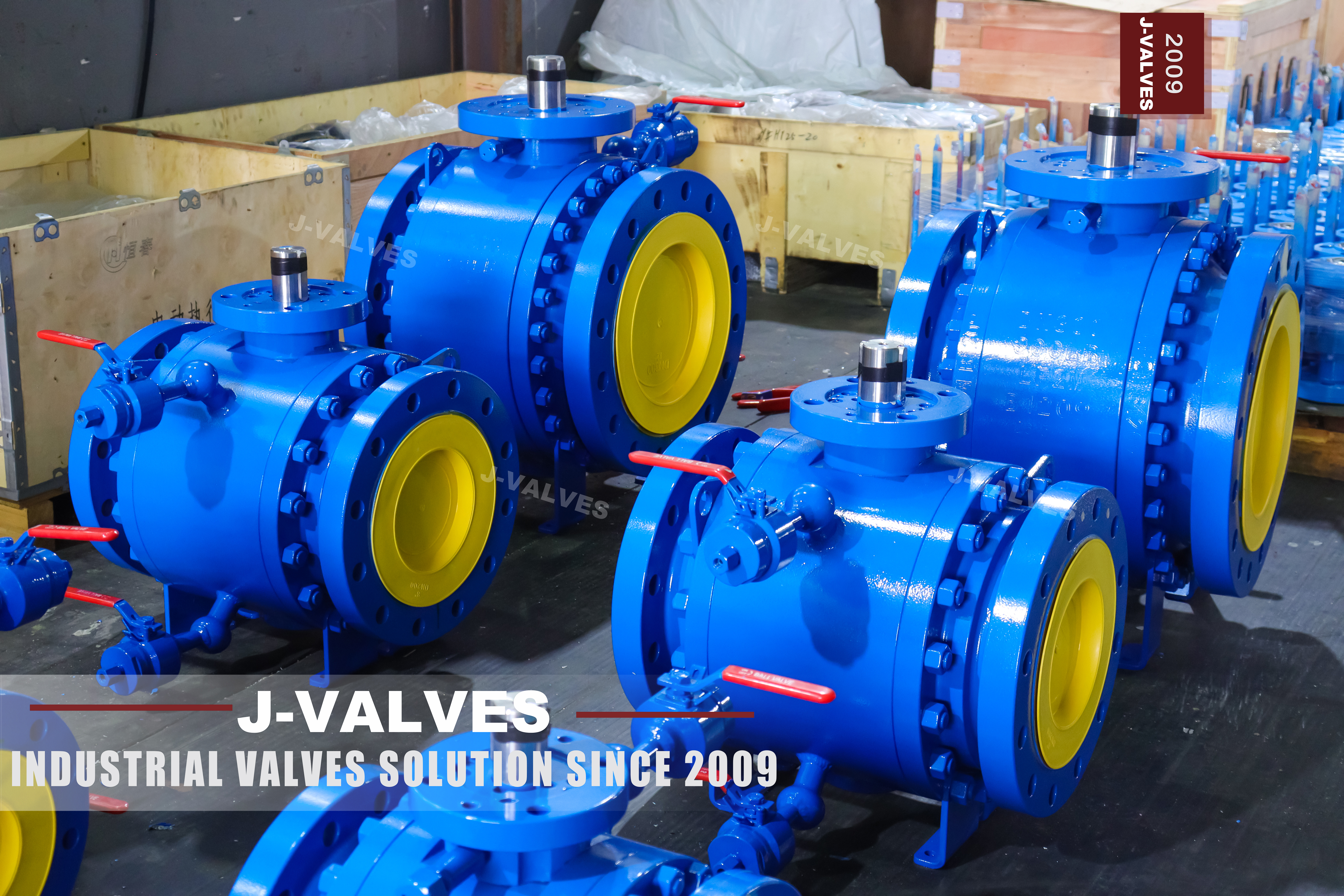
This is a three inch forged steel ball valve with a trunnion mounted ball, built in three bolted sections and closed by raised face flanges to EN 1092-1 at PN 25. The centre section in the photograph carries DN80 and PN25 in raised characters, with a material line below them that the paint and the image resolution do not let us read. That centre section holds the ball, both seat rings and both support shafts; the two end caps carry the flanges and bolt onto it. Nothing that wears is in the end caps, which is what makes the split worth having.
PN 25 needs one sentence of explanation, because it has no equivalent in the American system. It is an EN 1092-1 designation, defined as 25 bar nominal at 20 degrees Celsius. ASME B16.34 and API 608 work in Classes, and API 6D clause 7.2 pairs Class 150 with PN 20 and Class 300 with PN 50, so PN 25 sits between the two and is nobody's equivalent. A requisition written in PN has to be read against EN 1092-1; it cannot be translated into a Class without becoming a different valve.
The flange is the second thing to settle, and it is settled by counting holes. An ASME B16.5 Class 150 flange in NPS 3 has four bolt holes. The flange in the photograph has eight, evenly pitched, which is the EN 1092-1 PN 25 pattern for DN80. The original page carries both statements, EN 1092-1 in the parameter table and ASME B16.5 or B16.47 in the body text, and the valve in the photograph is the European one. B16.47 begins at NPS 26 and has nothing to do with a three inch valve at all. Two sister pages carry the same structure at DN300 in F316L and at eight inch in WCB; this page stays on the three inch PN 25 build, where the drilling and the face to face change with the size.
Design and Construction
Three sections, bolted. The left body and the right body each carry a flange, and both clamp onto the centre section, which holds the ball, the two seat rings and the trunnion supports. Undo the bolts and the centre section lifts out complete, leaving both flanges on their pipes. That is the reason to pay for a three piece body on a flanged line: the pipe does not move and no gasket face is disturbed at the far end of the run. The bolts sit outside the seal, so the joint is opened by loosening them, not by cutting anything.
The ball does not rest on the seats. It is held on an upper and a lower support shaft, and those shafts carry the thrust that line pressure puts on the ball. The stem therefore only turns the ball and is not loaded by pressure, which is why the operating torque stays low as the size grows and why a three inch valve can be worked by a lever. Up to four inch the two trunnions sit in the primary body; from six inch upward they sit in separate bearing blocks. On a floating valve the same pressure load goes straight into the seat and the stem.
The top of the body is a machined pad with actuator mounting holes, and the stem stands proud of it so that a drive can be coupled without opening the pressure boundary. The photograph shows a lever coupled to the stem through a red adaptor; a worm gear, a pneumatic actuator or an electric actuator uses the same pad. The stem is retained by the body and cannot be pushed out by pressure, and the packing sits under a gland that can be serviced with the line isolated. Pad size follows ISO 5211 by valve size, and the signed drawing states which one.
| Component | Standard Material | Optional Upgrade | Service Notes |
|---|---|---|---|
| Body, end caps, centre section | Forged steel as ordered: ASTM A105, A350 LF2, A182 F304, F316 or F51 | Any grade in the list, subject to the rating | Grade confirmed on the 3.1 certificate, not from the photograph |
| Ball | Matching body grade, hard chromium plated | Nitrided, or 316 / F51 for corrosive or abrasive duty | Plating thickness belongs on the drawing |
| Stem | 17-4PH stainless steel | 316 or F51 | Retained by the body; anti blowout is a body feature |
| Seat rings | RPTFE | PTFE, PEEK, or metal seat with cobalt alloy hardfacing | The seat sets the temperature limit of the valve |
| Seat springs | Stainless steel coil | Set matched to the seat arrangement | Spring load is a seat design value, not a medium value |
| Bearings and support shafts | 440C stainless with self lubricating liner | Nickel alloy bearings for high temperature | Bearing clearance is a drawing value |
| Stem packing | Flexible graphite with two O-rings | ISO 15848 tested arrangement | Triple barrier is the standard arrangement |
| Body bolts | Alloy steel stud and nut | Stainless steel for corrosive atmospheres | Torque to the signed drawing, cross pattern |
| Flanges | EN 1092-1 PN 25, raised face | ASME drilling as a separate product | Eight holes at DN80; ASME Class 150 has four |

Material Options
The body material on this page is a range, not a grade. The source data lists forged steel in ASTM A105, A350 LF2, A182 F304, F316 and F51, and the raised material line on the body is not legible in the photograph. The grade therefore has to come from the order and be confirmed on the EN 10204 3.1 certificate; neither this page nor the photograph can choose it. A buyer who needs a specific grade should write it into the enquiry rather than accept whichever forging is in the yard. The certificate is the only document that ties a heat number to a chemistry. Ask for the grade in writing at enquiry, and it is stamped on the body and carried on the certificate with the same heat number.
The range matters because the five grades are not interchangeable. A105 is the general purpose carbon steel and the economical answer for steam, water and air inside its temperature limits; A350 LF2 is the same carbon family with impact testing for cold service; F304 and F316 are austenitic stainless, with F316 preferred wherever chlorides are present; F51 is a duplex stainless with roughly twice the yield strength of the austenitic grades and good resistance to chloride stress corrosion. At room temperature A105 and LF2 are the same steel, and the difference shows up below zero.
Trim follows the body. The ball is the same material family with hard chromium plating or nitriding, the stem is 17-4PH, 316 or F51, and the seats are PTFE, RPTFE, PEEK or a metal seat with cobalt alloy hardfacing, with a nylon secondary seal behind it. The bearings are 440C stainless with a self lubricating liner. Whatever the body grade, the seat compound sets the temperature limit of the assembled valve and the packing sets its emission performance. A metal seat buys temperature and abrasion resistance and gives up the tight shut off of a soft seat.
Technical Specifications
The table holds values that come from the nameplate, from the source data sheet, or from a standard that lists them. Dimensions that belong to the build, including bolt circle, hole diameter, face to face and weight, are on the signed drawing, because they change with the flange standard and the bore ordered. Where a figure in the table and a figure on the drawing disagree, the drawing signed for that order governs, and the table is corrected from it.
| Item | Value |
|---|---|
| Size | DN80 (3 inch) |
| Pressure designation | PN 25 to EN 1092-1, 25 bar nominal at 20 degrees C |
| ASME equivalent | None; PN 25 falls between Class 150 (PN 20) and Class 300 (PN 50) in API 6D clause 7.2 |
| Body material | Forged steel, grade stated on the order: ASTM A105, A350 LF2, A182 F304, F316 or F51 |
| Body construction | Three piece, bolted end caps, centre section removable with the line isolated |
| Ball support | Trunnion mounted, upper and lower shafts in the primary body up to 4 inch |
| Bore | Full port or reduced port, stated on the order |
| End connection | Flanged, raised face, EN 1092-1 PN 25 |
| Flange drilling at DN80 | 8 bolt holes, as counted on the flange in the photograph |
| Face to face | On the signed drawing, to EN 558 for the size and rating ordered |
| Ball | Material matching the body, hard chromium plated or nitrided |
| Stem | 17-4PH, 316 or F51 stainless steel |
| Seat | PTFE, RPTFE, PEEK, or metal with cobalt alloy hardfacing |
| Seat arrangement | Single piston effect as standard; double piston effect on request |
| Bearings | 440C stainless steel with self lubricating liner |
| Stem sealing | Triple barrier: two O-rings and a graphite gasket |
| Body cavity | Drain and vent combined in one port up to 4 inch |
| Seat injection | Emergency sealant fitting, optional at DN80 |
| Top mounting | Pad with actuator holes; stem drive above the pad |
| Testing | API 598, shell at 1.5 times the rating and seat at 1.1 times |
| Certificate | EN 10204 3.1, heat number matched to the body marking |
Three lines in that table need reading against a standard. PN 25 is 25 bar at 20 degrees Celsius by definition, while Class 150 in carbon steel is rated 19.6 bar (285 psi) at 38 degrees Celsius in B16.34, so the two are not interchangeable and a line rated at 25 bar cannot take a Class 150 valve. The rating curve is European: EN 1092-1 gives allowable pressure against temperature for PN 25, and B16.34 has no row for it. The two systems also differ in flange thickness, so a PN 25 flange is not an ASME flange with four extra holes drilled in it. And the face to face dimension comes from EN 558 for a flanged valve of this rating, not from ASME B16.10, which tabulates ASME flanged valves by Class and has no row for PN 25.
The temperature line is the one most often copied wrongly. A single figure cannot cover the five body grades offered here: B16.34 places carbon steel and austenitic stainless in different material groups with different curves, and duplex has its own. The source data sheet prints one range for the whole family, and that range belongs to the carbon steel version. The same source prints 425 degrees C in the parameter table and 220 degrees C in the features block, and neither is labelled as body or seat, so a reader cannot tell which is which.
Standards and Compliance
ASME B16.34 supplies the wall thickness method and the material groupings, and it decides whether a body is thick enough for its rating. What it does not supply is a PN 25 rating, because its tables are indexed by Class. That gap is filled by EN 1092-1, which gives the flange dimensions, the drilling and the pressure temperature curve for PN 25. Both documents are needed, and they answer different questions: one sizes the metal, the other says what pressure that metal may carry at a given temperature.
API 608 is the product standard for metal ball valves with flanged, threaded, socket welding and butt welding ends, and it covers floating as well as trunnion designs. It works in Classes, and its flanged scope runs to DN 600 in Classes 150, 300 and 600 with flange dimensions taken from ASME B16.5, which is why an EN flanged valve sits outside its flange coverage even where the valve meets its other requirements. API 598 is the test standard and is independent of both. API 6D is a separate product standard and this page does not claim it.
Fire safety, fugitive emissions and sour service are separate qualifications. API 607, identical in method to ISO 10497, is a type test on a representative valve, not a test on every unit. ISO 15848 covers stem emissions and is a tested arrangement rather than a packing brand. NACE MR0175 with its twin ISO 15156 governs material for wet H2S service and brings hardness limits into the trim. None of the three is automatic; each is ordered and certified, or it is not claimed. A fire safe statement without a certificate number is a statement about intent.
| Requirement | Standard | What J-VALVES Supplies |
|---|---|---|
| Wall thickness and material grouping | ASME B16.34 | Body wall checked to the standard class; material group stated with the grade ordered |
| Pressure temperature rating at PN 25 | EN 1092-1 | Allowable pressure against temperature for the body grade supplied |
| Flange dimensions and drilling | EN 1092-1, DN80 PN 25 | Eight hole raised face flange, machined to the standard |
| Product standard | API 608 | Trunnion ball valve inside the flanged scope; note that its flange tables are ASME B16.5 |
| Pressure and seat test | API 598 | Shell at 1.5 times the rating, seat at 1.1 times, every unit, recorded |
| Fire test | API 607 / ISO 10497 | Type tested design; certificate number on request |
| Fugitive emissions | ISO 15848 | Tested stem arrangement when ordered |
| Material certificate | EN 10204 3.1 | Heat number matched to the body marking |
Manufacturing Process
The body starts as a forging. On a PN 25 valve the wall is not thick, so the advantage of a forging is not strength but soundness: a forged section has no shrinkage cavity to open into a leak path, and the material can be examined by ultrasonic testing where the order calls for it. The forging is machined on all faces, the bore is roughed and finished, and the seat pockets are cut to take the seat rings and their springs. A dense flange neck matters as much as the wall, because that is where a casting defect would show up as a leak at the gasket.
The centre section carries the two tolerances that decide whether the valve works. Its end faces must be flat and parallel, because each joint to an end cap is a face seal held only by bolt tension, and a face out of parallel leaks on one side no matter how hard the bolts are pulled. Those same faces are the gasket seats, so flatness is a sealing dimension and not a cosmetic one. The two trunnion bores must be coaxial with the ball axis, because a ball held off centre loads one seat harder, raises the torque and wears that seat first.
Assembly runs in a fixed order: seats and springs, ball, upper and lower shafts with their bearings, stem and packing, then the end caps and their bolts, tightened in a cross pattern in two or three passes to the drawing value. Marking follows, carrying size, rating, material and heat number, and painting comes last so that no paint covers a character. The heat number is the only link between the marking on the body and the certificate that travels with it. Bolt torque is quoted dry or lubricated, because the two give different tension from the same wrench setting.

Quality Control and Testing
Every unit gets a shell test at 1.5 times the rating and a seat test at 1.1 times, to API 598, and both are recorded against the serial number. On a three piece body the shell test is largely a test of the two bolted joints between the centre section and the end caps, because that is the only pressure boundary on the valve that is not a single piece of metal. Where the seats are double piston effect, the seat test is run from both sides, because both seats seal in both directions.
Flange inspection is the step that matters most on a European valve sold into an ASME market. Hole count, hole pitch and raised face finish are checked against EN 1092-1 for DN80 PN 25, and the face is checked for score marks, because a scored raised face leaks and no gasket repairs it. A valve with the right hole count on the wrong pitch circle bolts up on one side and binds on the other, which is discovered on site with the line already opened. Pitch is checked with a template, not by eye, for the same reason.
Material verification closes the loop. The heat number on the body is matched to the 3.1 certificate, and the certificate is read for grade, chemistry and mechanical properties. A 3.1 certificate reports the heat analysis and the mechanical results for that heat; it does not carry a heat treatment record or an ultrasonic report unless those are ordered as supplementary requirements. Ultrasonic testing of the forging sits under ASTM A388 for that reason. Where the service is sour, stem and ball hardness is tested against the NACE limit before the trim is released.
| Step | What Is Checked | Standard or Acceptance |
|---|---|---|
| Incoming material | Heat number, grade, certificate | EN 10204 3.1 matched to the marking |
| Body machining | Wall thickness, end face flatness and parallelism | Drawing dimensions and tolerance |
| Trunnion bores | Coaxiality with the ball axis | Drawing tolerance |
| Flange | Hole count, hole pitch, raised face finish and flatness | EN 1092-1, DN80 PN 25 |
| Assembly | Bolt torque in cross pattern, two or three passes | Torque value on the signed drawing |
| Shell test | Bolted joints between centre section and end caps | API 598, 1.5 times the rating, no leakage |
| Seat test | Leakage past each seat, one side at a time | API 598, 1.1 times the rating |
| Final | Marking, painting, certificate pack | Marking complete before painting; documents with the valve |

Applications and Industry Service
Three inch PN 25 flanged valves sit on utility and steam headers, boiler feedwater lines, compressed air mains, secondary district heating circuits and water treatment distribution. These are lines where the valve is worked often, where the pressure is high enough to matter, and where a flanged joint is wanted because the line has to come apart for inspection. A trunnion valve suits the duty because the torque stays low and the seats can be replaced without cutting the pipe. A flanged valve is chosen over a welded one wherever the line is opened on a schedule.
Double block and bleed is available here, with one condition the source text states and most pages leave out. Up to four inch the drain and the vent are combined in a single port on the lower side of the body, so the cavity can be isolated by the two seats and bled through that one port. The port is a screwed NPT plug, so a bleed valve can be fitted on site or supplied with the order. A procedure written around two separate tappings has to be changed, and it is cheaper to change it at enquiry than on site.
Three duties this valve is not for, all of which the source page claims elsewhere on the same page. It is not a subsea valve, so API 6DSS does not apply to it. It is not a wellhead valve, so API 6A PSL 4 does not apply either. And it is not a cryogenic valve: the body grades offered here are carbon and austenitic stainless for ambient and elevated service, and a minus 196 degree claim belongs to a different product with an extended bonnet and a different seat. Claiming those three duties is how a valve ends up on a line it was never built for.

Installation, Operation and Maintenance
A flanged joint is more forgiving than a thread and less forgiving than it looks. Bring the pipe flanges into line before the bolts go in, use a gasket rated for the medium and the temperature, and tighten the bolts in a cross pattern in two or three passes to the drawing value. Do not use the bolts to pull a misaligned pipe into place: the flange is then loaded on one side, the gasket takes a set, and the body carries bending it was not designed for. A spiral wound gasket wants a flat face and full bolt load; a graphite sheet gasket tolerates less.
Support the pipe on both sides, because a valve is not a pipe support. Operation is a quarter turn with a travel stop, so the open and closed positions are unambiguous, and the valve is for isolation, fully open or fully closed; throttling puts the seat and the ball edge in the flow path where erosion is fastest. If the valve is to be automated, the pad on top takes the bracket and the stem takes the coupler, and the torque sent to the actuator supplier has to be measured on the assembled valve.
Maintenance is the three piece advantage. Isolate and drain the line, take out the bolts, lift the centre section with the ball, seats and shafts still inside it, and renew the seats, the body gaskets and the stem packing as a set. The end caps stay on the pipe, so no flange is broken and no pipe is moved. Check the ball and the raised faces for damage before reassembly, clean the cavity while it is open, and do not reuse a body gasket that has already been compressed.
How to Specify and Order
An enquiry needs eight lines: size and bore, DN80 full port or reduced; pressure as PN 25 together with the flange standard, which on this valve is EN 1092-1; body grade chosen from A105, A350 LF2, A182 F304, F316 or F51 rather than left open; ball and stem grades where the project names them; seat compound against a stated temperature and medium; operation, lever or gear or actuator; testing and documents, API 598 by default plus the 3.1 certificate; and marking, where the customer's own specification governs it.
Two of those lines go wrong most often. The flange is first, because a DN80 PN 25 flange has eight holes and an NPS 3 Class 150 flange has four, and no gasket bridges that difference, so a valve bought on the wrong one is scrap. The holes cannot be redrilled afterwards either, because their position is set from the raised face and the casting around them. The grade is second, because the page offers five and the photograph cannot choose between them: an enquiry that leaves the grade open gets whichever forging is in the yard.
What ships with the valve is a documentation pack: the 3.1 certificate matched to the heat number on the body, the shell and seat test records, and the drawing that carries the bolt circle, the face to face and the bore which this page deliberately does not print. A fire certificate, an ISO 15848 report or a NACE statement is ordered with the valve, because each attaches to a specific unit and a specific heat. Ask for the drawing before the order, not after the valve arrives.
FAQ
Q: Is PN 25 the same as Class 150 or Class 300?
A: Neither. PN 25 is an EN 1092-1 designation defined as 25 bar nominal at 20 degrees C. ASME B16.34 and API 608 work in Classes, and API 6D clause 7.2 pairs Class 150 with PN 20 and Class 300 with PN 50, so PN 25 sits between the two with no Class equivalent at all. The numbers are close enough to look interchangeable and are not: Class 150 in carbon steel is rated 19.6 bar (285 psi) at 38 degrees C in B16.34, so a line specified at 25 bar cannot take a Class 150 valve, and a Class 300 valve is heavier and more expensive than the duty needs.
Q: Will this valve bolt onto an ASME Class 150 pipe flange?
A: No. A DN80 PN 25 flange has eight bolt holes and an NPS 3 Class 150 flange has four, on a different pitch circle and at a different flange thickness. The valve is supplied to EN 1092-1, and the mating flange has to be to the same standard. If the line is ASME, the valve has to be ordered with ASME drilling, which is a different build and a different page; a gasket does not bridge the difference and the holes cannot be redrilled, because their position is set from the raised face.
Q: Is the face to face dimension to ASME B16.10, as the old page says?
A: No. B16.10 tabulates ASME flanged and welding end valves by Class and has no PN 25 row, so it cannot describe this valve. A flanged valve to EN 1092-1 takes its face to face from EN 558, for the size and the rating series ordered. The figure goes on the signed drawing rather than on this page, because it changes with the flange standard and the bore.
Q: Can this valve do double block and bleed?
A: Yes, with one qualification that the source text states and most pages leave out. Up to four inch the drain and the vent are combined in a single port on the lower side of the body, so the cavity can be isolated by the two seats and bled through that one port. A procedure written around two separate tappings therefore has to be changed. The port is a screwed NPT plug, so a bleed valve can be fitted on site or supplied with the order.
Q: The page gives two temperature limits, 425 and 220 degrees C. Which one applies?
A: They describe different parts, and the source page does not say which is which. The higher figure is the body range for the carbon steel version; the lower one is where a soft seat stops. The assembled valve is limited by the seat compound, not by the body, so a valve ordered with RPTFE is limited at the seat even though the body could go further. That is why the temperature and the medium have to be stated at enquiry: the seat is then selected against them instead of being left at the default.
Q: Which body material will I actually receive?
A: Whichever grade is written on the order. The product is offered in ASTM A105, A350 LF2, A182 F304, F316 and F51, and the material line on the body in the photograph is not legible, so neither the picture nor this page can choose it. State the grade at enquiry and it is stamped on the body and confirmed on the EN 10204 3.1 certificate against the heat number. An enquiry that leaves it open gets whichever forging is in the yard.


Hot Products


News
Ball Valves in A Kraft Pulp Mill: Black Liquor, Green Liquor And The Cost of Choosing The Alloy by Habit
White liquor at pH 14 cracks carbon steel welds, black liquor sets solid below 100 C, green liquor dregs grind seats: alloy choice and torque in a kraft mill.
Read More
Slug Flow And Ball Valves: What Actually Arrives At The Seat
A slug is liquid mass with momentum, not a pressure spike. What changes at the seat, in the cavity and at the actuator when liquid reaches a ball valve.
Read More
Ball Valves in Direct Lithium Extraction: PH 1 Eluate, Gypsum Scale And 438,000 Cycles in Twenty-Five Years
Direct lithium extraction swings valves from pH 1 eluate to pH 12 caustic, 48 column switches a day and gypsum scale. Materials, seats and torque.
Read More
Ball Valves in Geothermal Brine: Silica Scale, Chloride Cracking And The Cooling Trap
Why geothermal brine destroys ball valves: retrograde silica scale, calcite at the flash point, chloride cracking above 60 C and the 250 C seat limit.
Read More