


CHINA J-VALVES Offers Various High-quality I ndustrial Ball Valves
J-VALVES, a distinguished professional ball valve manufacturer rooted in China, takes pride in its extensive product portfolio. Our offerings span a wide range, including trunnion-mounted ball valves, floating ball valves, high-temperature ball valves, high-pressure ball valves, metal-sealed ball valves, ultra-low temperature ball valves, DBB ball valves, Three-way And Four-way Ball Valve, and fully welded ball valves. Each product is a testament to our commitment to precision engineering and reliable performance. Meticulously crafted, they are designed to not only meet but exceed the most stringent industrial demands, ensuring stable operation even under extreme conditions. This enables us to provide our clients with high-value services and makes our valves widely sought-after in industries.
Product Category
Contact Us


-
J-VALVES-Q347F
-
J-VALVES
Overview of the J-VALVES 8 x 6 Inch Class 150 Trunnion Ball Valve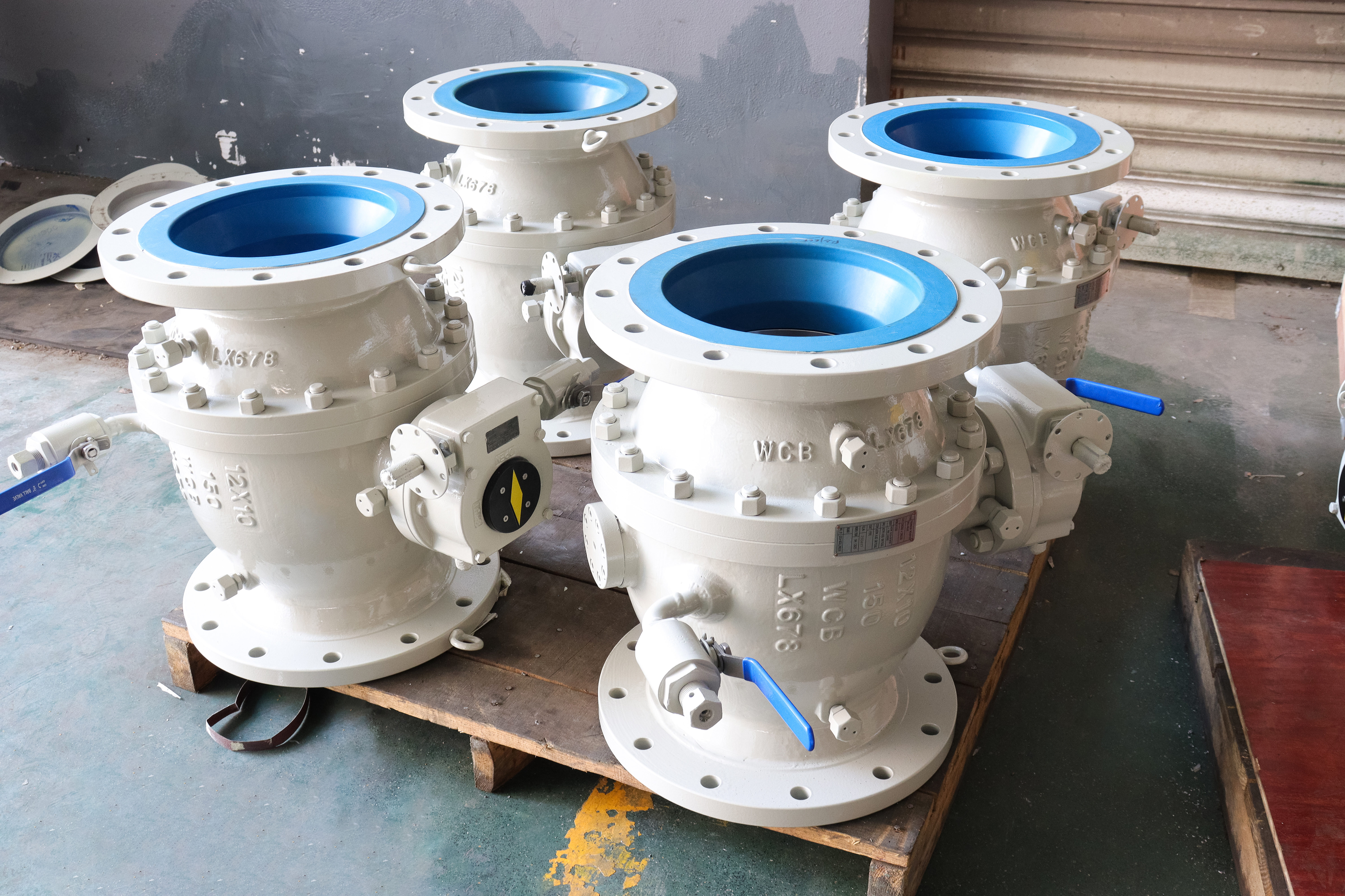
This is a three piece trunnion mounted ball valve with eight inch ends and a 150.0 mm port, a forged A105 body in Class 150, reinforced PTFE seats and raised face flanges. Two numbers describe it and they disagree on purpose. The ends are eight inch and the port is six, so everything that touches the pipe belongs to the larger valve while everything the medium touches belongs to the smaller one. The flanges, the face to face, the two joint rings and the weight are those of an NPS 8 valve. The ball, both seats, the seat pockets, the cavity and the bore are those of an NPS 6 valve. That split is the whole design, and it is why this size is bought at all.
Class 150 is the one class where the body is never the constraint. A forged A105 body at this size, asked to hold 19.6 bar at ambient temperature, is not being asked a hard question, and no wall thickness on the drawing is going to be the reason a valve fails here. What decides whether the valve is still tight in five years sits somewhere else: in the polymer seat, in the two body joints, on the two gasket faces, and in what is left standing in the cavity. Those four items are the subject of this page, and they are the four items that a data sheet written around the pressure class never mentions.
The service this valve belongs in is the ordinary one: utility and cooling water headers, plant air, tank farm and pump suction isolation, low pressure process lines, and the block valve on a branch that will be operated a few times a year. It is not a pipeline valve in the sense that term is used in API 6D, because the moment a line is pigged, swept or gauged, a six inch port in an eight inch body disqualifies the valve. That single limitation decides more enquiries than any other, and it is cheaper to say it on the first screen than to find it out at the drawing stage.
Design and Construction
The body is three pieces: a centre section and two end caps, closed by two rings of studs. The centre section carries the ball, both seat rings, the upper and lower trunnions and the stem, and the end caps carry one seat each and close the flow path. Photographs of this pattern show studs with a nut at each end rather than cap screws, which is the right choice on a joint that is expected to be opened more than once, because a stud that has been stretched stays a stud while a cap screw's thread in a forged body wears every time it is turned.
Each of the two joints is a gasketed pressure boundary, and both faces are machined as a pair while the halves are bolted together. That is what makes them match, and it is also what makes them not interchangeable with the joint of another valve of the same size. Gaskets are consumables, the studs are not, and neither joint may be opened until the line is isolated and the cavity drained. Three piece construction buys access without cutting or springing the pipe: the end caps stay on the line flanges and the centre section comes out complete with its seats and stem. It does not buy maintenance under pressure, and no configuration of this valve does.
The ball runs on two trunnions in bearings that are carried by the body, so the thrust from the line pressure goes into the body instead of into the seat, and the stem turns the ball without carrying any of that side load. At this size the arrangement earns its cost twice. First, the seat is not asked to hold the weight of the ball: on a floating design the ball rests on the downstream seat ring, and a heavy ball pressing on a polymer ring for years is one of the ways a large soft seated valve loses its low pressure tightness. Second, the breakaway torque stays low enough that a small actuator can operate the valve, which is the reason the pad on top matters more than the gear ratio.
The top works in the photographs is a worm gearbox whose input side is a machined, drilled pad concentric with a bare square drive. No handwheel is fitted on the unit photographed, so the first line of any order is whether the handwheel ships with the valve or whether the pad is there for an actuator to be fitted later, and at what F size and drive dimension. This is not a detail to be settled after the order: the pad and the drive belong to the valve, and the coupling that joins them to somebody else's actuator has to be made to match both.
Two small ball valves are piped off the body, one near the high point and one at the low point, each ending in a plug with spanner holes. These are the cavity vent and the cavity drain, and the fact that each has its own quarter turn isolation valve changes the way the valve is proved. With the main ball closed, the cavity is sealed between the two seats. Open the drain, let whatever is in the cavity out, and watch: if the cavity refills and the drain keeps running, the upstream seat is passing, and if the flow stops the upstream seat is holding. That is a double block and bleed check done at the valve, with two small handles, without breaking a single flanged joint and without a wrench.
The bore and the raised face in the photographs are blue while the rest of the body is light grey, and the body line on the plate carries a coating alongside A105. A coated bore on a carbon steel valve is a decision, not a finish, and three things follow from it. The coating has to be named in the order, because an un-named coating cannot be inspected. It has to be checked for thickness and for holidays, because a coated bore is bought to keep the medium off the steel and a pinhole defeats the purchase. And it has to be off the gasket face: a raised face is a machined sealing surface, and a gasket compressed onto paint relaxes as the paint creeps, which arrives at the flange as a torque loss nobody can explain three weeks later.

Material Options
The body is ASTM A105, forged and normalized. A105 and A216 WCB sit in the same ASME B16.34 material group, group 1.1, so the pressure temperature rating on the plate is the same for a forging and a casting and nothing about the class changes when the body is forged. What the forging buys here is a barrel machined from solid with two joint faces and two seat pockets cut into it, and a certificate that describes a forging. What it does not buy is a higher rating, and any quotation that offers forged construction as a way of reaching a higher class is describing something the standard does not contain.
Normalizing is a heat treatment condition and it is either on the certificate or it is not. A data sheet that says normalized, and an inspection certificate that states no heat treatment, describe two different objects, and the discrepancy is worth raising before the valve is painted because after painting there is nothing left to inspect. The same applies to impact testing: neither A105 nor A216 lists charpy testing as a routine acceptance item, so a minimum temperature on the plate means the rating curve has a defined value there, not that the steel was tested at that temperature.
The plate itself lists alternatives rather than a material. It gives the body as A105, the ball as A105 or F304, and the stem as A182 or F304. That is normal for a plate that covers a family, and it has one practical consequence: the plate cannot be used as an inspection criterion for the trim. What identifies the ball and the stem of a particular valve is the certificate, and if the order does not pin the trim down, the valve is compliant with its own plate whichever combination arrives. A buyer who needs to know should write the ball and stem grades on the order and check the heat numbers on the certificate against the ones stamped on the body.
| Component | Standard Material | Optional Upgrade | Service Notes |
|---|---|---|---|
| Body and end caps | ASTM A105 forging, normalized | A350 LF2 for low temperature | Same B16.34 group as A216 WCB, the rating does not change |
| Ball | A105 with hard chrome, or F304 | F316, or F304 with hard chrome | The plate offers a choice, the certificate decides |
| Stem | A182 F304 or F316 | 17-4PH where strength governs | Antistatic path runs through the stem |
| Seat rings | Reinforced PTFE as stamped | PTFE, or PPL for higher temperature | The governing temperature of the whole valve |
| Seat insert | Polymer with a metal shoulder behind it | Metal seat for abrasive duty | The shoulder is the fire safe backup path |
| Body joint gasket | Spiral wound, graphite filler | Graphite sheet for severe cycling | Only one gasket type belongs on this joint |
| Stem packing | Flexible graphite | Graphite with a lantern ring | Adjustable, replaceable only when isolated |
| Trunnion bearings | Stainless with PTFE or graphite liner | Bronze backed bearing | Carry the thrust, not the stem |
| Antistatic device | Spring loaded plunger, ball to body | None needed | Measured, not assumed, on a polymer seat |
| Bolting | ASTM A193 B7 with A194 2H nuts | B8M for wet or coastal sites | Joint studs are not pipe flange bolts |
| Internal coating | Named coating on the bore | Coating free bore on request | Thickness, holidays and masking all matter |
| External finish | Paint system to the agreed specification | Colour to the client's standard | Carbon steel is painted, that is correct here |
Technical Specifications
| Item | Value |
|---|---|
| Product type | Three piece trunnion mounted ball valve, reduced bore, flanged |
| Nominal size | 8 x 6 inch, DN200 ends by DN150 port as stamped on the plate |
| Port diameter | 150.0 mm, the API 6D minimum for an 8 x 6 valve in Class 150 to 600 |
| Full bore reference | 201.0 mm, the API 6D minimum for a full bore NPS 8 in the same classes |
| Pressure class | Class 150, recorded as PN 20 in API 6D clause 7.2 |
| Rating | 19.6 bar at 38 C, 285 psi at 100 F, ASME B16.34 group 1.1 |
| Body material | ASTM A105 forged carbon steel, normalized |
| Seat material | Reinforced PTFE as stamped on the plate |
| Temperature, body | -29 to +425 C, the group 1.1 span |
| Temperature, valve | Set by the seat, not by the body |
| End connection | Raised face flange, ASME B16.5 Class 150, NPS 8 |
| Flange outside diameter | 342.9 mm |
| Bolt circle | 298.4 mm, eight bolts of three quarter inch |
| Raised face diameter | 269.7 mm |
| Face to face | 457 mm, the NPS 8 Class 150 value, not the NPS 6 value of 394 mm |
| Body joints | Two gasketed joints, faces machined as a pair |
| Cavity ports | Vent at the high point and drain at the low point, each with an isolation valve |
| Operation | Worm gearbox with a drilled actuator pad, handwheel by agreement |
| Design standard | ASME B16.34 with API 6D |
| Test standard | API 598 and API 6D, shell at 1.5 times and seat at 1.1 times the rating |
| Documentation | EN 10204 3.1 certificate, test records, signed GA drawing |
Standards and Compliance
| Requirement | Standard | What J-VALVES Supplies |
|---|---|---|
| Shell design and wall thickness | ASME B16.34 | Calculated to the group 1.1 table for NPS 8 Class 150 |
| Product standard | API 6D | Trunnion mounted construction, cavity vent and drain, DBB check |
| Pressure temperature rating | ASME B16.34 table 2-1.1 | The rating curve for the material group, not a single number |
| Flange dimensions | ASME B16.5 Class 150 | Eight bolt NPS 8 pattern, raised face |
| Face to face | ASME B16.10 and API 6D | The NPS 8 Class 150 value confirmed on the GA drawing |
| Bore | API 6D table 1 | 150.0 mm, the reduced bore figure for 8 x 6 |
| Shell and seat test | API 598 and API 6D | 1.5 times and 1.1 times the rating, records issued |
| Fire safe | API 607 with ISO 10497 | Certificate by type test, covering this size and class |
| Antistatic | API 6D and API 608 | Device fitted and measured across ball, stem and body |
| Marking | API 6D | Plate with size, class, body, trim and heat number |
| Material certificate | EN 10204 3.1 | Heat numbers matching the stamps on the body |
Three things are worth separating, because a data sheet that lists standards in one line makes them look interchangeable. ASME B16.34 gives the wall and the rating curve. API 6D gives the product requirements, including the cavity vent, the drain and the double block and bleed provision that the two small valves on the body exist to serve. API 598 gives the test pressures and the acceptance. None of the three says anything about the seat material, which is why the temperature on the plate is a body statement and the temperature in the order book is a seat statement.
API 608 does not belong on this sheet. It is a product standard for metal ball valves with flanged, threaded and welding ends, and it accepts a seat test done one side at a time, which is a different acceptance from the cavity pressurisation that API 6D uses to prove both seats in one operation. Listing the two side by side is a habit copied from catalogue pages, and it leaves the reader unable to say which test the valve was actually accepted against. A trunnion mounted valve with a cavity vent and a drain is an API 6D object, and this page says so.
PN 20 is a designation and not a flange. API 6D clause 7.2 records Class 150 as PN 20, so the number belongs on the plate and in a European enquiry, but EN 1092-1 has no PN 20 grade at all, and a European buyer who orders on the strength of that number will be offered a PN 16 flange, which is a different part with a different bolt circle and a metric thread. The rating behind the designation is the B16.34 table value, so 19.6 bar at 38 C and less as the temperature rises, and no reading of the letters changes that.
Manufacturing Process
The body starts as a forging, is normalized, and is then machined in two stages. The first stage cuts the bore, the flange faces and the outside form. The second stage cuts the seat pockets and the two joint faces, and it is done with the halves bolted together so that the joint is machined as an assembly rather than as two parts that are expected to meet. That order of operations is the reason a joint can be reopened several times without the faces losing their match, and it is also the reason a replacement end cap is not a stock item.
The seat pockets are the second place where clearance matters more than it looks. A polymer seat ring is held in a pocket and pushed against the ball; the gap between the ring and the pocket wall is what allows the polymer to be squeezed without being extruded, and at Class 150 the pressure is not what threatens it. What threatens it is the pocket being cut generous because a generous pocket is easier to assemble. A seat that has room to move has room to lose contact, and the loss shows up at low pressure first.
Coating comes after machining and before assembly, and the masking is the step to watch. The bore is coated because the medium is meant to see coating and not steel. The raised faces on both ends are not coated, because a gasket has to seat on metal. The threaded cavity ports are masked or plugged, because a coated thread strips its coating on the first assembly and leaves flakes in the cavity. Any of these three done in the wrong order is invisible in a photograph and expensive in service.
Assembly is followed by the shell test, the seat test and a function check, in that order, because a seat result is meaningless if the shell has not held. Then the cavity is drained and the ports are plugged, the plate is fixed, and the ends are capped. A valve of this size leaves the works painted, and the paint is not cosmetics: on a carbon steel body in a plant atmosphere it is the corrosion allowance.

Quality Control and Testing
| Step | What Is Checked | Standard or Acceptance |
|---|---|---|
| 1 Material | Certificate against the stamps, heat numbers on body and caps | EN 10204 3.1, A105 normalized stated |
| 2 Trim identity | Ball and stem grade recorded, not inferred from the plate | Certificate, because the plate lists alternatives |
| 3 Port | Gauge through the port with the ball open | 150.0 mm, the 8 x 6 figure, written into the test record |
| 4 Joint faces | Flatness and finish of both faces, with the halves bolted | Machined as a pair, no coating, no damage at the gasket land |
| 5 Cavity ports | Thread condition, plug and small valve fitted and free | Vent and drain each operable by hand |
| 6 Shell test | Body and both joints under pressure | API 598 and API 6D, 1.5 times the rating, no leakage |
| 7 Seat test | Each seat, cavity pressure method | API 598 and API 6D, 1.1 times the rating |
| 8 Cavity check | Drain opened with the ball closed, both seats proved | Double block and bleed, result recorded |
| 9 Coating | Dry film thickness and holiday test on the bore | Agreed specification, gasket faces verified bare |
| 10 Function | Open and close, torque recorded at the gearbox input | Within the declared operating torque |
| 11 Marking | Plate content against the order and the certificate | API 6D marking, heat number legible |
| 12 Packing | Ends capped, cavity drained, plate protected | Flange faces protected, no desiccant contact with the bore |
Step three is the one that gets argued about and it costs nothing. An eight inch valve and an eight by six valve look the same from the end of a pipe, because the flange, the bolt pattern and the face to face are identical. The only thing that separates them is the port, and the only way to prove the port at goods inwards is to open the valve and put a gauge through it. A test record that says 150.0 mm is worth more than a photograph of the plate, because the plate does not carry the port.
Step nine is the one that gets skipped. Coating thickness is measured with a gauge on a coated bore and the result means nothing without a holiday test, since a coat of the right thickness with a pinhole in it is a corrosion cell with a large cathode. The gasket faces are checked in the same step, from the other direction: they must be bare, and the inspection is by eye and by solvent, not by drawing.

Applications and Industry Service
The valve suits water, cooling water, plant and instrument air, non aggressive process lines, tank farm manifolds and pump suction and discharge isolation where the duty is blocking rather than control. It is also the ordinary choice where an eight inch line needs a block valve and the budget has to be spent on the flange size rather than on the bore, because the six inch port costs less in ball, seats and cavity than a full bore eight inch while the pipework stays eight inch.
It does not suit four situations, and saying so is more useful than a list of applications. It does not suit a line that will ever be pigged, swept or gauged, because the port is smaller than the pipe and the tool will not pass. It does not suit a line where pressure drop matters, because a 150.0 mm port in a 201.0 mm bore line is a permanent restriction and the loss grows with the square of the flow. It does not suit a duty that needs two independent barriers proved in both directions, because the standard seat is single piston effect and relieves the cavity upstream, which is a feature and not a fault but is not a positive double barrier. And it does not suit a medium above the seat's temperature or one that attacks carbon steel, because the body is A105 and the seat is a polymer, and neither is a corrosion resistant choice.
On water service there is one more question, and it belongs to the coating rather than to the valve. A coated bore in a potable water line is a material in contact with drinking water, and the coating has to be declared with its approval, not just its colour. On cooling water the same coating is a straightforward corrosion measure and the question is thinner. Either way the answer comes from the coating specification, not from the fact that the bore is blue in the photograph.
Installation, Operation and Maintenance
Before the valve is bolted in, look at the two raised faces. They should be bare machined metal. If they carry the same coating as the bore, take it off, because a gasket on paint is a joint that will relax. The same applies to the pipe flange faces, and the check is worth doing on the ground rather than at height with the valve on the bolts.
The line bolts are not the joint studs. An NPS 8 Class 150 flange takes eight bolts of three quarter inch, and the studs that close the two body joints are a different set with a different length, ordered against the drawing. Keeping a spare set of joint studs and a spare pair of joint gaskets is sensible on a valve that will be opened for seats; expecting the pipe flange bolts to serve both is how a joint ends up half threaded.
Mount the valve with the gearbox up and the drain at the lowest point of the cavity. The vent belongs where a person can reach it without dismantling anything, because the cavity check is a routine action and an inaccessible vent turns a two minute job into a shutdown. On a line that is drained for winter, open the drain and let the cavity empty: a closed valve full of water is a small vessel with no expansion space, and the drain exists for exactly that.
To prove the seats, close the valve fully, open the drain, and watch what comes out and whether it stops. Then open the vent and repeat. Between the two ports, a person can tell which seat is holding without breaking a joint, and the result is worth writing down, because the same test after a year tells you whether the seat is losing its memory or whether the medium has damaged it.
Do not put a bar on the handwheel and do not force the valve against its stop. The gearbox is the weakest link between a hand and a ball, and a valve that will not turn at this class is usually holding trapped liquid rather than suffering from a tight seat, so the first action is to vent the cavity rather than to increase the lever. The packing can be adjusted with the line under pressure; the joints cannot be touched, and neither can the seats.
How to Specify and Order
Write the size as 8 x 6, not as eight inch. The ends and the port are two different numbers and the only place they are both recorded is the order and the plate. If a full bore eight inch is what the line needs, say so at the enquiry, because the two valves share a flange and a face to face and cannot be told apart from the outside.
Pin the trim. The plate offers a choice of ball and stem, so the order has to name the grade, and the certificate has to carry the heat numbers that match the stamps. State the seat material and the temperature it has to survive together, because a seat chosen for temperature alone may be the wrong seat for a medium that leaves deposits.
State the ends, the operation and the coating. Raised face flanges per B16.5 are standard here and a ring joint face is a different body. Say whether the gearbox ships with a handwheel or as a bare pad, and at what F size and drive dimension if an actuator is intended. Name the internal coating, its thickness and whether it is required on the bore only or nowhere, and ask for the holiday test result with the test records.
Ask for the GA drawing before the order is placed. Three items live on it and nowhere else: the face to face as built, the joint stud size and length, and the drain and vent positions. On a three piece valve the drawing is also the only document that says which of the two joints is which, which matters the first time a seat has to be changed with the valve in the line.
FAQ
Q: Can this valve be pigged or swept?
A: No, and the answer comes from the port rather than from the class. The ends are eight inch but the bore is 150.0 mm, which is the API 6D minimum for an eight by six valve and is exactly the minimum for a full bore six inch valve. An eight inch tool cannot pass it, and a six inch tool has no reason to be in an eight inch line. If the line will ever be pigged, swept or gauged, order full bore, which carries 201.0 mm at this class, and accept the larger ball, seats and cavity that come with it.
Q: The plate says the ball is A105 or F304. Which one is in my valve?
A: The plate cannot tell you, because it covers a family and lists the alternatives. What identifies the trim of a particular valve is the EN 10204 3.1 certificate and the heat numbers stamped on the body. Two practical consequences follow. Write the ball and stem grades on the order so that the certificate has something to be checked against, and do not use the plate as an inspection criterion at goods inwards, because a valve with a carbon steel ball and a valve with a stainless ball carry the same plate.
Q: The raised face is painted in the photographs. Is that a problem?
A: It is a problem if it is still there when the valve is bolted. A raised face is a machined sealing surface and a gasket has to seat on metal. Paint under a gasket creeps, the joint relaxes, and the flange arrives at a torque check three weeks later reading low for no visible reason. The bore coating is a different matter and may be a legitimate specification item, so ask what it is, how thick, and whether it was holiday tested, then take it off the two faces and leave it in the bore.
Q: Why does a Class 150 valve at this size have a gearbox?
A: Not for torque. At this class and with a 150.0 mm port the operating torque is small, and the reason the top works is a gearbox is that the valve is usually bought as an actuated package: the photographs show a machined, drilled pad concentric with a bare square drive and no handwheel. So the question to settle on the order is whether the handwheel ships with the valve or whether the pad is there for somebody else's actuator, and if so at what F size and drive dimension.


Hot Products


News
Ball Valves in A Kraft Pulp Mill: Black Liquor, Green Liquor And The Cost of Choosing The Alloy by Habit
White liquor at pH 14 cracks carbon steel welds, black liquor sets solid below 100 C, green liquor dregs grind seats: alloy choice and torque in a kraft mill.
Read More
Slug Flow And Ball Valves: What Actually Arrives At The Seat
A slug is liquid mass with momentum, not a pressure spike. What changes at the seat, in the cavity and at the actuator when liquid reaches a ball valve.
Read More
Ball Valves in Direct Lithium Extraction: PH 1 Eluate, Gypsum Scale And 438,000 Cycles in Twenty-Five Years
Direct lithium extraction swings valves from pH 1 eluate to pH 12 caustic, 48 column switches a day and gypsum scale. Materials, seats and torque.
Read More
Ball Valves in Geothermal Brine: Silica Scale, Chloride Cracking And The Cooling Trap
Why geothermal brine destroys ball valves: retrograde silica scale, calcite at the flash point, chloride cracking above 60 C and the 250 C seat limit.
Read More