


CHINA J-VALVES Offers Various High-quality I ndustrial Ball Valves
J-VALVES, a distinguished professional ball valve manufacturer rooted in China, takes pride in its extensive product portfolio. Our offerings span a wide range, including trunnion-mounted ball valves, floating ball valves, high-temperature ball valves, high-pressure ball valves, metal-sealed ball valves, ultra-low temperature ball valves, DBB ball valves, Three-way And Four-way Ball Valve, and fully welded ball valves. Each product is a testament to our commitment to precision engineering and reliable performance. Meticulously crafted, they are designed to not only meet but exceed the most stringent industrial demands, ensuring stable operation even under extreme conditions. This enables us to provide our clients with high-value services and makes our valves widely sought-after in industries.
Product Category
Contact Us


-
J-VALVES-Q47F
-
J-VALVES
Overview of the J-VALVES 6 x 4 Inch Class 2500 F316 Three-Piece Trunnion Ball Valve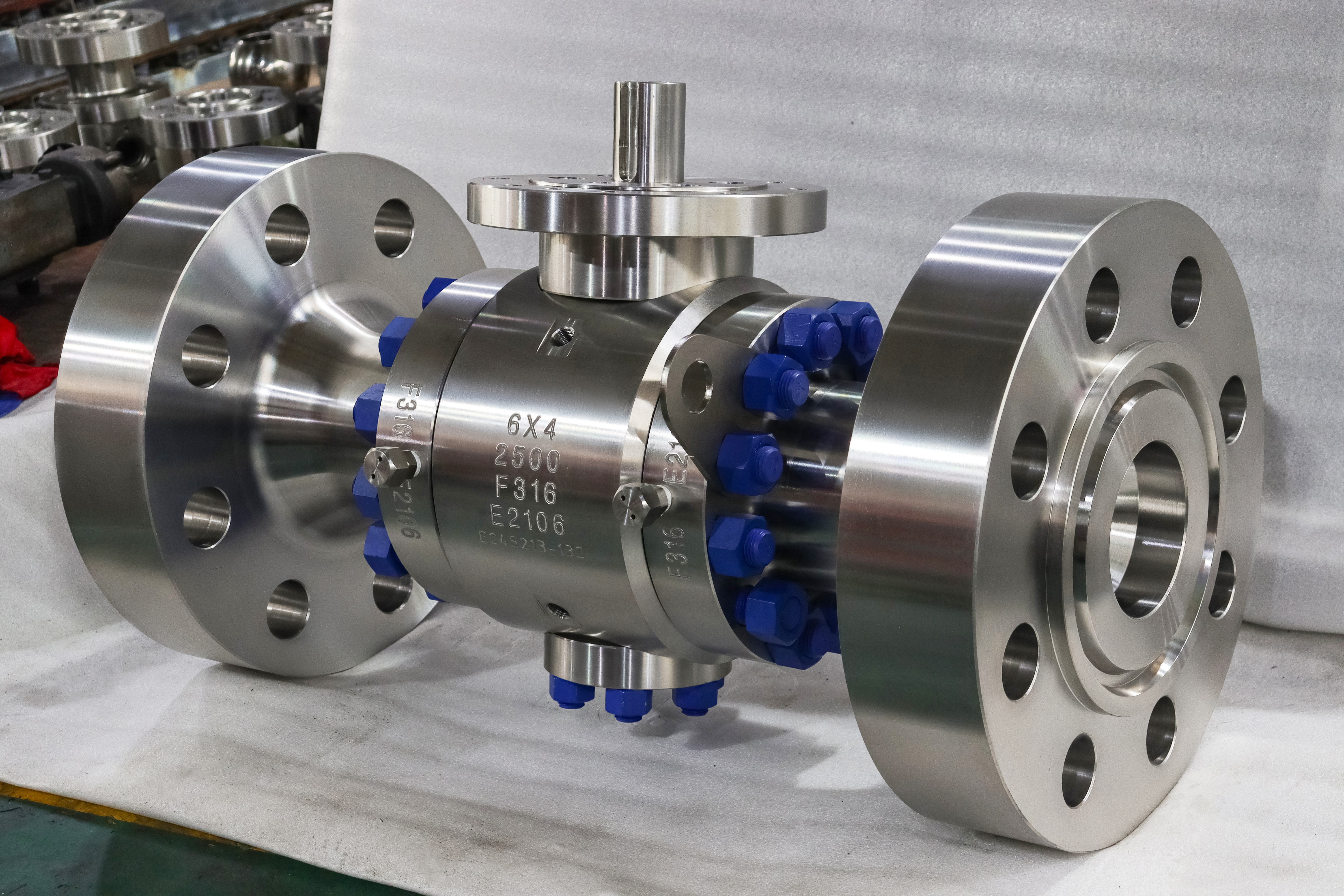
This is a six inch Class 2500 trunnion mounted ball valve with a four inch port: forged A182 F316, three piece side entry, ring joint flanges, metal seated. The body carries four lines of marking, and two of them describe different bores. The six is the pipe size, the flange and the pressure boundary. The four is the flow passage. Almost everything worth knowing about this valve follows from that pair, and almost nothing about it can be read off the outside.
The obvious alternative is a four inch valve with a reducer at each end, and it is worth counting what that costs. Two reducers on a line at this class are two more welds or two more flanged joints, two more pressure boundaries to certify, and extra length in a spool that then has to be re-made, because the face to face dimension of a four inch valve is not the dimension of the six inch valve it replaces. A 6 x 4 is one body, with the flange and the face to face of the six inch valve, so it drops into the space and the only thing that changes is the flow area.
What that costs is not in the body, it is in the flow. The shell is sized for six inches and the port is 100 mm, so the same volume passes through a smaller area and moves faster than it would in the pipe. At the same time the thrust that reaches the seats and the trunnions scales with the port, not with the pipe, so the bearings, the seat springs and the operator all get an easier job than they would on a full bore valve of the same size and class. Load down, velocity up. Those two effects point in opposite directions, and an order written with only one of them in mind is how a 6 x 4 ends up either overbuilt at the operator or underbuilt at the trim.
Design and Construction
Three pieces means a centre section carrying the ball cavity, the two seat pockets and both trunnion bores, with a cap bolted to each end. The caps carry the flange, the ring groove and one seat pocket each; the centre carries everything that has to line up with the ball. Two bolted joints sit on the pressure boundary, which is the price of being able to lift the centre out without cutting the pipe. That argument belongs to every three piece valve and is not what makes this one different.
What makes it different is that the ball is not a four inch ball. It has to be large enough to be carried by the two trunnions and to hold the seat rings, so its outside diameter follows the six inch body, and only the through hole is 100 mm. The seat rings, the trunnion spacing and the cavity around the ball are therefore six inch parts. A 6 x 4 is a six inch valve with a smaller hole in it, not a four inch valve in a larger body, and it is priced, weighed and lifted as the former.
The passage is stepped. Inside the ring groove the flange bore is NPS 6; it steps down to the port before the upstream seat, runs through the ball, and steps back up on the downstream side. Those two steps are where the flow changes speed and direction, so they are the first places to look for erosion in dirty service and for deposits in service that carries solids or scales. Whether the step is a square shoulder or a cone is a machining decision that shows on the drawing, and it is worth asking about rather than assuming.
The cavity deserves its own paragraph, because it is the part of this valve that is most often reasoned about from the wrong number. The volume between the two seats, around the ball, is the volume of a six inch body, not of a four inch one, so a 6 x 4 traps more liquid when it is closed than its bore suggests. That liquid expands when the line warms up, and what happens next is decided by the seat effect rather than by the port: a single piston effect seat discharges the cavity to the low pressure side, a double piston effect seat does not and needs an external relief. Sizing the relief from the bore is a mistake that only shows up on a hot line.
The ball is held between an upper and a lower trunnion running in bearing blocks carried by the centre section, so it does not travel axially and the seats are never asked to hold the line thrust. The stem transmits torque and nothing else. In the photograph the stem carries a keyed drive and a machined mounting pad with no operator fitted, which is the honest way to photograph it: on a valve at this class the operator is chosen against measured torque, not against the size of the valve.

Material Options
The body, the caps and the centre section are forged A182 F316, and F316 is stamped on the body beside the size and the class, so a buyer can read the grade off the valve and check it against the certificate without translating a house code. Molybdenum at two to three percent is what the grade buys, and it is bought for chlorides and acidic condensate rather than for strength.
The material decision that actually matters on this valve is not the body. Because the port is smaller than the pipe, the trim works harder than the shell: the highest velocity in the whole assembly is at the seat contact band and at the edge of the ball port, and that is where erosion and cavitation damage begin. So the choices worth spending on are the ball surface and the seat facing, and the right question is what the medium carries, not what class the valve is.
The seat is metal as the primary seal, an F316 ring with a cobalt alloy facing lapped against the ball, with a polymer insert behind it that does work only at low differential. The insert is also the temperature ceiling of the whole valve: RPTFE near 200 C, PEEK near 260 C, and above that the insert is gone and the valve is metal seated, still sealing but at the acceptance rate a metal seat is allowed. A data sheet that offers a polymer seat and the full body temperature range in the same line is offering two valves.
The stem is 17-4PH for torque and bending rather than for corrosion, and on a sour line the acceptance is a condition on hardness rather than a grade name, so sour service has to be declared at inquiry. The trunnions run in 440C bearings with a self-lubricating liner, with Inconel available where the medium rules the bearing out. Bolting is A193 B7 with A194 2H as the default and B8M where the specification asks for stainless throughout.
| Component | Standard Material | Optional Upgrade | Service Notes |
|---|---|---|---|
| Body, caps and centre section | Forged ASTM A182 F316 | Other austenitic grades on request | Grade, size, class and heat number stamped on the body |
| Ball | F316, hard chrome plated or nitrided | F316L, tungsten carbide or cobalt alloy overlay | Coating follows solids and velocity, not class |
| Seat ring | F316 with cobalt alloy facing, metal to metal | Soft insert as secondary seal | Metal is the primary seal at this class |
| Seat insert | RPTFE | PEEK, nylon | Governs the temperature ceiling of the valve |
| Stem | 17-4PH | F316 with ENP, Inconel 718 | Hardness limited on sour service |
| Trunnion and bearings | Hardened F316 or 17-4PH, 440C bearings | Inconel bushings | Bearing blocks carried in the centre section |
| Body joint gasket | Spiral wound, graphite filler | Ring joint at the pipe flange | One per joint, renewed at every break |
| Packing | Flexible graphite | Low emission set to ISO 15848 | Two O-rings and graphite above the shoulder |
| Body studs | A193 B7 with A194 2H | A193 B8M with A194 8M | Torque figures travel with the drawing |
| Operator | Selected against measured torque | Gear, pneumatic, electric or gas over oil | Mounting pad to ISO 5211 |
Technical Specifications
The table separates what a standard fixes from what the order fixes. The bore is the one dimension that is also on the nameplate and in a standard table; the rest follows the pattern and the trim, and is confirmed on the signed drawing rather than published as a catalogue number that may belong to another build.
| Item | Value |
|---|---|
| Nominal size | 6 x 4 inch, DN150 x DN100 |
| Bore | 100.0 mm minimum, the reduced bore value of API 6D table 1 for NPS 6 |
| Pressure class | Class 2500, recorded as PN420 in API 6D clause 7.2 |
| Body material | Forged ASTM A182 F316, stamped on the body |
| Body style | Three piece, centre section between two bolted end caps |
| Ball support | Upper and lower trunnion in bearing blocks |
| Seat | Metal primary with a polymer insert as secondary seal |
| End connection | RTJ flange to ASME B16.5 Class 2500, eight stud holes |
| Face to face | ASME B16.10 value for NPS 6 Class 2500, confirmed on the GA drawing |
| Body temperature | Minus 29 to 425 C |
| Seat temperature | RPTFE near 200 C, PEEK near 260 C, metal above that |
| Governing limit | The lower of the body and the seat, not the higher |
| Stem sealing | Two O-rings plus graphite, anti blowout shoulder |
| Design standard | ASME B16.34 and API 6D |
| Test standard | API 598, shell at 1.5 times rating, seat at 1.1 times |
| Fire test | API 607, equivalent to ISO 10497 |
| Operation | Operator on an ISO 5211 pad, selected against measured torque |
Standards and Compliance
The 6 x 4 designation comes out of a table rather than out of a catalogue. API 6D table 1 lists a minimum bore for each size and class, and for NPS 6 the reduced bore figure is 100.0 mm, which is what the shorthand means. A buyer who would rather not use the shorthand can write NPS 6 reduced bore to API 6D table 1 and get the same valve, and a buyer who wants something between the table value and full bore is asking for a special bore, which is available but is a drawing item rather than a stock one.
The flange is a straight ASME B16.5 NPS 6 Class 2500 ring joint flange with eight stud holes, and it is the same flange whether the valve behind it is full bore or 6 x 4. The face to face dimension comes from ASME B16.10, keyed to size and class, so the reduced bore does not shorten the valve either. That is the mechanism behind the argument in the overview: everything the pipe touches is six inch, and the only place the four inch bore appears is inside, behind the ring groove, where nobody looks during installation.
API 6D governs the design as a pipeline valve, and it is the document this valve is built and marked against. API 598 sets the test pressures and leaves acceptance to the seat type, which matters here because a metal seat is not held to zero visible leakage; a specification asking for a metal seat and zero leakage is asking for two different valves. Fire testing is API 607 with ISO 10497 as the equivalent, and the certificate covers a size and class range rather than a single valve, so the range is what should be checked. Anti static continuity, the cavity relief provision and the anti blowout stem are construction requirements of API 6D rather than test results, and ISO 5211 fixes the operator mounting.
| Requirement | Standard | What J-VALVES Supplies |
|---|---|---|
| Pressure boundary design | ASME B16.34 | Wall thickness and rating for the austenitic group at Class 2500 |
| Product standard | API 6D | Bore to table 1, cavity relief, marking, nameplate with both designations |
| Flanges | ASME B16.5 Class 2500 | RTJ facing, ring groove to B16.20, eight stud holes |
| Face to face | ASME B16.10 | Dimension for NPS 6 Class 2500 confirmed on the GA drawing |
| Shell and seat test | API 598 | 1.5 times rating shell, 1.1 times seat, both directions, recorded |
| Fire test | API 607 and ISO 10497 | Certificate stating the size and class range it covers |
| Sour service | NACE MR0175 and ISO 15156 | Hardness controlled parts, declared at inquiry |
| Material certificate | EN 10204 3.1 | Heat numbers agreeing with the body stamp |
Manufacturing Process
The centre section carries the work. The two seat pockets, the two trunnion bores and the port are machined in one part in a sequence that keeps them on a common axis, because the port has to be concentric with both seat pockets and the trunnions have to be square to that axis before the caps are fitted. The step from the NPS 6 flange bore down to the port is cut after the port, so the transition is a machined feature rather than whatever is left at the end of a bore.
The ball is plated after the port is finished, and the lapping that follows is restricted to the seat band. Doing it the other way round, plating a finished ball and then grinding the seat band, leaves the coating intact where it is least needed and thin where the velocity is highest, at the port edge.
The caps are not shared with the full bore valve of the same size. The flange and the stud pattern are the same, which is what makes the two valves interchangeable in a pipe, but the seat pocket and the ring land are cut for a different ball, so a cap from a full bore 6 inch valve will bolt onto this body and will not seal against this seat. Spares have to be ordered against the bore, and the same applies to seat kits and to balls.

Quality Control and Testing
One check exists on this valve that does not exist on a full bore one, and it is the one most likely to be skipped: bore verification. Nothing outside the valve distinguishes a 6 x 4 from a full bore 6 inch valve. The flange is the same, the face to face is the same, the studs are the same, and the marking is a line of characters on a machined surface. A go and no go gauge through the port, with the result written on the test sheet against the table value, is the only proof that the valve in the crate is the valve on the order.
Material identification is the second. The heat number on the body is checked against the 3.1 certificate, and the grade is confirmed on the body itself. Forging quality is a separate question: A182 asks for chemistry and tensile properties, and ultrasonic examination of the forging is a supplementary requirement ordered to the practice in ASTM A388, so a standard 3.1 file does not contain an examination result. Where the shell is thick or the service is sour, that requirement belongs on the purchase order, not in an assumption.
| Step | What Is Checked | Standard or Acceptance |
|---|---|---|
| 1 | Incoming forging, heat number and certificate | EN 10204 3.1, chemistry and mechanicals to A182 F316 |
| 2 | Ultrasonic examination where ordered | ASTM A388 practice, report against the order |
| 3 | Port and step machining | Bore gauge against API 6D table 1 and the GA drawing |
| 4 | Seat pocket, trunnion bores and ring groove | Position and profile to the GA drawing |
| 5 | Hardfacing and lapping | Facing thickness, bond, contact band on the ball fitted |
| 6 | Shell test | API 598, 1.5 times rating, no leakage |
| 7 | Seat test in both directions | API 598, 1.1 times rating, each seat separately |
| 8 | Cavity, drain and vent | Function proven with the ball closed |
| 9 | Torque and operation | Full travel, torque recorded against the order value |
| 10 | Marking and paperwork | 6X4, 2500, F316 and heat number, with the 3.1 file |

Applications and Industry Service
The natural home for a reduced bore valve at this class is a line whose size is set by the network rather than by the flow. Injection headers, letdown stations, metering runs, test benches and high pressure chemical plant all share the shape: the header is six inch because everything else on it is six inch, and the flow through this particular valve is what a four inch line would carry. Putting a 6 x 4 in that seat keeps one pipe size, one flange standard and one spool length across the station.
Pressure letdown is the clearest case. The valve isolates around a control valve, sees full differential closed and almost none open, and the reduced port means the drop across the valve is bought once instead of being paid for on every hour of operation. Test benches and hydrostatic stands use the same valve for the opposite reason: at this class the trim has to survive repeated cycling at full differential, and a smaller port is a smaller seat to hold.
Three duties belong elsewhere. A line that is or may become piggable cannot use a reduced bore, because a pig sized for six inches will not pass a four inch port and the restriction cannot be removed later. A line carrying solids should think about velocity before it thinks about the valve, since the port already runs faster than the pipe. And a line that expects to need full flow after a debottleneck should buy full bore now, because the difference is a body, not a trim.
Installation, Operation and Maintenance
The valve hangs from a lug on the body, visible in the photograph beside the flange, and that is where a sling goes. Slings around the stem, the mounting pad or the studs load parts that were not designed for it, and on a forging of this mass the damage is done before anyone notices. The pipe should not be asked to carry the valve either; supports under the body take the weight and keep the bending out of the two joints.
The ring is a single use item. It deforms to fit the groove, so it is replaced at every break, and the groove is covered until the joint is closed because a scored groove passes a visual check and leaks afterwards. Bolts are lubricated and tightened in a crossing pattern in stages to the figure on the drawing, with the faces brought up parallel, since a cocked flange loads one side of the ring and the leak appears at the first thermal cycle.
Operation is a quarter turn, and the operator is sized against the measured torque rather than chosen from a table by size; that is why the pad is on the valve and the gear or actuator is a separate line on the quotation. On this valve the reduced port is what makes a smaller operator possible, so an operator chosen for a full bore valve of the same size is oversized and will overload the stem on the closed stop.
Maintenance splits where the pressure boundary splits. With the valve closed and the cavity vented, the packing and the upper stem seals can be renewed with the line live, which is the only work this valve allows under pressure. Seats and ball need the line isolated and a body joint opened, and at this size that is a planned lift of the centre section rather than a hand job. Seat kits and caps are specific to the 6 x 4 build, not to the size and class.
How to Specify and Order
Six answers make the quotation exact. The bore, stated as 6 x 4 or as NPS 6 reduced bore to API 6D table 1, because the two are the same valve and the shorthand is what appears on the nameplate. The seat effect, single or double piston, because that decides whether the cavity relieves itself or needs an external device and on a valve with this much trapped volume it is not a detail. The ring material and the facing, since the ring is bought separately and is not part of the valve. The operator, with its mounting pattern and the torque requirement, and whether it is to be supplied at all. The medium, with its solids content and its chloride level, because that is what selects the ball coating and the seat facing rather than the class. And whether the line will ever be pigged, now or after a future debottleneck.
Three documents close the gap between what is ordered and what arrives. The general arrangement drawing, which fixes the face to face, the ring groove, the support positions and the withdrawal clearance for the centre section. The 3.1 certificate with heat numbers for body, ball and stem, checked against the stamp on the body. And the test records, shell and seat, with the bore verification written on them, because that line is the only evidence that the valve in the crate has the port that was ordered.
FAQ
Q: Can a 6 x 4 valve be converted to full bore later?
A: No, and the reason is that only the shell is shared. The ball, both seat rings, the seat pockets and the ports through the caps are cut for a 100 mm passage, so opening the valve to full bore means replacing every internal part and both caps, which is a new valve. The honest way to decide is at the order: if the line may be pigged, or may need full flow after a debottleneck, buy full bore now. The cost of changing the decision afterwards is the cost of a second valve, not of a trim kit.
Q: Why use a reduced bore at Class 2500 at all?
A: Because two things get easier and one gets harder, and the trade is worth making on the right line. The thrust that reaches the seats, the trunnions and the operator scales with the port rather than with the pipe, so a smaller port lets a smaller operator and lighter bearings do the same isolation duty at the same rating. The shell, the flanges and the face to face stay at six inch, so nothing in the pipe changes. What gets harder is the flow: the same volume through a smaller port moves faster, so the seat and the ball port edge see more velocity than a full bore valve would give them, and the pressure drop is bought for the life of the line.
Q: The flange is the same as a full bore valve, so how do I know what was delivered?
A: By gauging the port, because nothing outside the valve will tell you. A 6 x 4 and a full bore 6 inch valve of the same class share the flange, the stud pattern, the face to face and the ring groove, and the difference is a line of characters stamped on the body plus the hole behind the groove. That is why the inspection sheet for this valve carries a go and no go gauge result against the API 6D table 1 value, and why the reading should be on the test record rather than in a verbal assurance.
Q: Can this valve be repaired with the line still in service?
A: Only the stem seals. With the valve closed and the cavity vented, the packing and the upper stem O-rings can be renewed while the line stays at pressure, because the stem is retained by the body and cannot be blown out. Everything else, including both seats and the body joints, needs the line isolated and drained first, since every one of those operations opens the pressure boundary. A quotation that offers in-line seat replacement without isolation is describing a different product.


Hot Products


News
Ball Valves in A Kraft Pulp Mill: Black Liquor, Green Liquor And The Cost of Choosing The Alloy by Habit
White liquor at pH 14 cracks carbon steel welds, black liquor sets solid below 100 C, green liquor dregs grind seats: alloy choice and torque in a kraft mill.
Read More
Slug Flow And Ball Valves: What Actually Arrives At The Seat
A slug is liquid mass with momentum, not a pressure spike. What changes at the seat, in the cavity and at the actuator when liquid reaches a ball valve.
Read More
Ball Valves in Direct Lithium Extraction: PH 1 Eluate, Gypsum Scale And 438,000 Cycles in Twenty-Five Years
Direct lithium extraction swings valves from pH 1 eluate to pH 12 caustic, 48 column switches a day and gypsum scale. Materials, seats and torque.
Read More
Ball Valves in Geothermal Brine: Silica Scale, Chloride Cracking And The Cooling Trap
Why geothermal brine destroys ball valves: retrograde silica scale, calcite at the flash point, chloride cracking above 60 C and the 250 C seat limit.
Read More