


CHINA J-VALVES Offers Various High-quality I ndustrial Ball Valves
J-VALVES, a distinguished professional ball valve manufacturer rooted in China, takes pride in its extensive product portfolio. Our offerings span a wide range, including trunnion-mounted ball valves, floating ball valves, high-temperature ball valves, high-pressure ball valves, metal-sealed ball valves, ultra-low temperature ball valves, DBB ball valves, Three-way And Four-way Ball Valve, and fully welded ball valves. Each product is a testament to our commitment to precision engineering and reliable performance. Meticulously crafted, they are designed to not only meet but exceed the most stringent industrial demands, ensuring stable operation even under extreme conditions. This enables us to provide our clients with high-value services and makes our valves widely sought-after in industries.
Product Category
Contact Us


-
J-VALVES-Q647F
-
J-VALVES
Overview of the J-VALVES Pneumatic Three-Piece Forged Steel Trunnion Ball Valve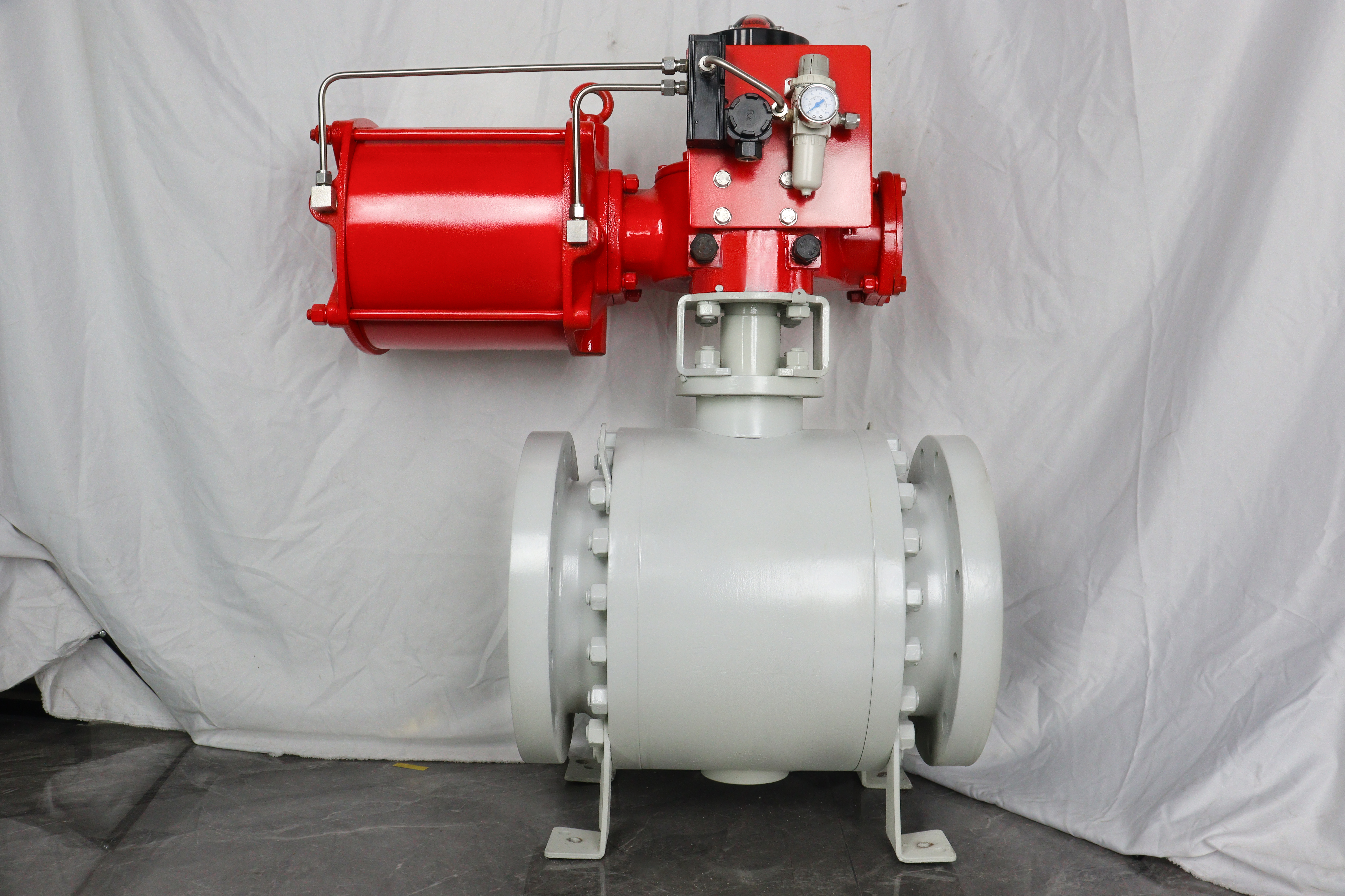
This is a quarter-turn isolation valve that arrives with its operator already on it. The body is forged steel, split into a centre section and two bolted end caps; the ball runs on an upper and a lower trunnion rather than resting on its seats; the ends are flanged to ASME or EN; and a pneumatic actuator on the top flange turns the stem through ninety degrees on plant air. What makes it one product rather than a valve with a box bolted on is that body and actuator are matched before either is machined.
The pairing matters because of where the load goes. Pressure on the closed ball is carried by the two trunnions into the body, so the stem sees torsion and not bending, and breakaway torque stays low enough for a spring-return actuator of sensible frame size. That is why this construction is chosen toward the top of the size range: a floating ball on the same duty would need a larger actuator, a heavier bracket and a bigger air supply, and every one of those is a new way for the package to fail.
Typical work is isolation that has to happen with nobody at the handwheel: emergency shutdown on a gas lateral, a meter and regulating station, a compressor header, a tank farm manifold, a remote block valve at an unmanned site. In those places the actuator is not a convenience, it is the part that decides whether the valve moves when the signal is lost. Which way it moves is a process decision, and it has to be taken before the spring is chosen.
Design and Construction
Start with the trunnion, because everything else follows from it. The ball is held by a shaft above and a shaft below, each running in a bearing, and the pressure load passes through those shafts into the body rather than into the seats. At the small end both trunnions are housed in the primary body; from the middle of the range upward they run in two separately bored bearing blocks machined as a pair, so the two axes stay common for the life of the valve.
The three-piece body is what makes an actuated package serviceable. The stem, the bracket and the actuator all sit on the centre section, so when the two body joints are opened the whole assembly - ball, seats, stem, bracket and actuator - lifts out as one piece, and the end caps stay bolted to the pipe. Nothing has to be re-aligned on site, because the alignment never left the centre section. The price is two pressure joints, each with its own gasket and ring of studs.
The actuator interface is where datasheets most often go wrong. A ball valve is a part-turn machine, so its mounting is ISO 5211, which fixes the flange code, the bolt circle and the square or keyed drive bore. ISO 5210 is the multi-turn interface written for gate and globe valves and will not fit. Accessories mount on the NAMUR pattern of VDI/VDE 3845, which exists so that a pilot valve can sit directly on the actuator instead of on a bracket with two more tubing runs to leak.
Seat type decides what the actuator has to hold. With single piston effect seats, upstream pressure pushes the seat onto the ball and downstream pressure pulls it away, so a cavity overpressure from trapped liquid vents into the line and nothing has to be added to the body. With double piston effect seats both sides push the seat toward the ball, which gives a barrier each way but leaves the cavity with no relief path, so an external relief device is required - one more opening in the pressure boundary.

Material Options
A105 is the default forging and the right starting point. It sits in Group 1.1 of ASME B16.34, its allowable pressures are the tabulated carbon steel values, and no extra wall thickness changes them; what forging buys over casting is soundness, not class. A350 LF2 is the low temperature answer and carries its own impact test. A182 F304 and F316 answer chlorides and process corrosion. A182 F51 and F53, the duplex grades, answer chloride stress cracking where 316 is not enough.
The grade ladder is a temperature ladder, and a range sheet hides that. A duplex body cannot use the whole of the minus 29 to plus 425 C window printed on the data sheet: 2205 is good for continuous service to about 300 C, with an ASME ceiling of 315 C, and above that the ferrite phase embrittles. Super duplex does not raise the ceiling, it raises corrosion resistance. So a hot line and a chloride line pull the body grade in opposite directions.
| Component | Standard Material | Optional Upgrade | Service Notes |
|---|---|---|---|
| Body and end caps | ASTM A105 forged | A350 LF2; A182 F304 or F316 | Forging buys soundness, not a higher class |
| Ball | A105 with ENP, or the body grade | Hard chrome; stainless | A coating, not a material grade |
| Trunnions | 17-4PH or the body grade | Surface hardened | Carry the thrust, so the stem sees torsion |
| Stem | 17-4PH | A182 F316; F51 for sour duty | Inside the NACE hardness limit |
| Seats and springs | PTFE on a metal shoulder, stainless springs | RPTFE, PEEK, PPL; metal with a Stellite face | The seat sets the temperature; the shoulder is the fire path |
| Stem sealing | Two O-rings and a graphite gasket | ISO 15848 low emission | The upper O-ring is the only part changeable live |
| Body joint gaskets | Spiral wound, graphite filler | 316L winding | Has to survive the fire test |
| Bearings | Metal backed, self-lubricating | 440C with a liner | Two blocks bored as a pair |
| Bolting | A193 B7 with A194 2H | B8 or B8M | B7 is the weak point on a stainless valve |
| Actuator and seals | Rack and pinion, nitrile seals | Scotch yoke; Viton seals | ISO 5211 mounting, VDI/VDE 3845 accessories |
Technical Specifications
The table below describes the range, not one valve. Every row carrying a number is a limit of the construction; the figures for a particular valve are on the general arrangement drawing signed with the order. Face to face, actuator frame size and bracket height are drawing items rather than catalogue ones, because all three change with the size and with the accessories that have to fit around the valve and still leave room to swing a handwheel.
| Item | Value |
|---|---|
| Nominal size | 2 to 56 inch, DN50 to DN1400, trunnion construction |
| Pressure class | 150 to 2500LB |
| Rating source | ASME B16.34 group 1.1; Class 2500 is 6170 psi at 100 F, falling with temperature |
| Temperature, shell | Minus 29 to plus 425 C, carbon steel body |
| Governing limit | The lower of body grade and seat material |
| Body material | ASTM A105 forged, options above |
| Ball and bore | Trunnion mounted, full or reduced bore per API 6D Table 1, fixed at order |
| Seat | PTFE standard, metal on request |
| Seat design | Single piston effect standard, double on request |
| End connection | Flanged, raised face or ring joint facing |
| Flange standard | ASME B16.5 to NPS 24; ASME B16.47 Series A or B above |
| Face to face | Per the signed general arrangement drawing |
| Operator | Pneumatic, double acting or spring return |
| Air supply | 0.4 to 0.7 MPa, dry and filtered |
| Mounting | ISO 5211; accessories to VDI/VDE 3845 |
| Product standard | API 6D with ASME B16.34 |
| Test standard | API 598 and API 6D |
| Fire test | API 607 and ISO 10497 |
Standards and Compliance
One thing a range page cannot say is flanged to ASME B16.5, full stop. B16.5 stops at NPS 24. Above that the flanges are ASME B16.47, which exists in two dimensional series, A from MSS SP-44 and B from API 605, and the two do not interchange: the same size in the same class can differ in outside diameter, bolt circle, bolt count and bolt size. An order above NPS 24 has to name the series.
Fire qualification is a type test, and the certificate states the sizes and classes it covers. For a soft-seated quarter-turn valve the reference is API 607, technically aligned with ISO 10497. API 6FA was written for API 6A and API 6D valves and has since been withdrawn into API 607, so a sheet listing 607, 6FA and ISO 10497 together is describing one test up to three times. Check the certificate range against the line items.
| Requirement | Standard | What J-VALVES Supplies |
|---|---|---|
| Design and pressure rating | ASME B16.34 | Wall and allowable from the group table for the body grade |
| Pipeline valve design | API 6D | Trunnion construction, cavity relief, DBB and DIB stated per seat type |
| Pressure testing | API 598 and API 6D | Shell at 1.5 times, seat at 1.1 times, every valve |
| Fire qualification | API 607 and ISO 10497 | Type test certificate stating the range it covers |
| Flanges to NPS 24 | ASME B16.5 | Raised face or ring joint, drilling per class |
| Flanges above NPS 24 | ASME B16.47 Series A or B | Series named in the order |
| Actuator mounting | ISO 5211 | Flange code and drive bore on the drawing |
| Anti-static | API 6D | Ball to stem to body continuity, measured |
| Traceability | EN 10204 3.1 | Heat number from forging to certificate |
Manufacturing Process
The body starts as a forged billet, is normalised, hardness checked and traced by heat number. Centre section and both end caps are match marked before machining, and the joint faces with both bearing bores are cut with the parts bolted together, so the faces come out flat against each other and the two trunnion axes come out common. That single set-up is what the actuator depends on later: a bracket on a face that is not square to the stem axis side-loads the packing on every stroke.
The bracket is machined rather than shimmed, and its pilot diameter fits the actuator spigot so the two centres coincide. The actuator is stroked against the assembled valve and the mechanical stops are set so the ball lands on its seat without being driven past it, because over-travel marks a seat and then looks like a leak that appeared by itself. Open and closed are then set on the switch box and the indicator, and the package is cycled before it is packed.

Quality Control and Testing
Testing runs in two stages, and the order is deliberate. The valve is proved as a pressure vessel first, shell at one and a half times the rated pressure and seat at one and one tenth to API 598 and API 6D, with no actuator fitted, because a failure there is a body problem and should not be mistaken for a control problem. Only then does the actuator go on and the package get cycled on air at the lowest supply pressure the plant will guarantee.
| Step | What Is Checked | Standard or Acceptance |
|---|---|---|
| 1 | Forging and chemistry | Heat number, certificate, hardness after normalising |
| 2 | Machined geometry | Joint face flatness, flange facing, both trunnion bores in line |
| 3 | Ball and seat | Sphericity, finish, seat ring flatness, spring free length |
| 4 | Assembly | Seat squeeze, gland load, ball free by hand before the actuator |
| 5 | Shell test | 1.5 times rated, no leakage, no permanent distortion |
| 6 | Seat test | 1.1 times rated, each seat, acceptance per seat type |
| 7 | Actuator function | Cycle on air at the minimum guaranteed supply |
| 8 | Final | Torque record, anti-static reading, markings, documents |

Applications and Industry Service
The natural duty is gas: transmission laterals, meter and regulating stations, compressor headers, pig trap isolation, tank farm manifolds, and the block valves either side of a control valve that has to be isolated without stopping the line. Liquids follow the same logic wherever the valve is remote. In each case the reason for air rather than a handwheel is that the valve has to move on a signal; the reason for a trunnion is that the bore is large.
It is worth saying where this package is the wrong answer. A site without instrument air should have an electric actuator, not a pneumatic one with an air receiver, because the receiver is a single point of failure that nobody tests. Modulating duty needs a positioner and a seat that tolerates partial travel, which is a different valve. Sour service needs bolting and a stem inside the hardness limit of NACE MR0175, stated at enquiry rather than discovered at commissioning.
Installation, Operation and Maintenance
Installation is a piping job with an air and signal interface attached. Support the body where the line is not otherwise anchored, because a large actuated valve hangs a bracket, an actuator and its accessories off one flange. Bring the studs up in a cross pattern in several passes and use a gasket made for the raised face. Then the services: dry filtered air, the right thread form on the ports, and a solenoid that matches the actuator.
The fail position has to be agreed before the valve is built, because it sets the spring and the porting. A double-acting actuator has no fail position at all: on air failure it stays where it is, acceptable on a bypass and unacceptable on an emergency shutdown valve. A spring-return unit drives to its spring position when air is lost, and its spring is compressed in the running position, so the actuator holds stored energy throughout its service. The port count follows from the spring: a 3/2 solenoid for a spring-return unit, a 5/2 for a double-acting one.
Maintenance splits into two jobs usually run together in one sentence. The pressure boundary cannot be opened under pressure: both body joints are gaskets and studs like any other, and the line has to be isolated, drained and the cavity vented before either cap comes off. The one part that can be worked on with the line live is the upper stem seal, with the cavity vented and the stem still retained by the body. Everything on the actuator side is vented before a tool goes near it.
There is a second temperature to watch. Process temperature is inside the valve; what the actuator sees is ambient, and a standard nitrile seal kit is comfortable only from about minus 20 to plus 80 C. On a hot line the bracket is what keeps the actuator out of the radiant heat, so its height is an order item rather than something solved on site.
How to Specify and Order
Six answers settle the order: size and class; flange standard and, above NPS 24, the B16.47 series; the facing; the seat material against the real temperature rather than the range sheet; the body grade against the medium; and the fail position with the air supply the plant can actually guarantee. Two of them, the facing and the flange standard, have to be fixed before the body is machined. The accessories can follow the drawing, but the bracket has to know about them.
FAQ
Q: Can the valve be repaired without taking it out of the line?
A: The body can be opened without cutting pipe, and that is worth having, but it is not the same as working on a live line. Both body joints are pressure boundaries: the line has to be isolated, drained and the cavity vented before either end cap comes off. What the three-piece body saves is the pipe work - the end caps stay bolted to their flanges, no spool is cut and no flange is re-aligned - and the centre section leaves with the ball, both seats, the stem, the bracket and the actuator still on it. One part can be worked on with the line live, and only one: the upper stem seal, with the cavity vented and the stem still retained by the body.
Q: Do I need a spring-return actuator or a double-acting one?
A: That is a safety question before it is a price question. A double-acting actuator needs air to open and air to close, and if the supply fails it stays exactly where it is, so there is no fail position at all. On a bypass that is acceptable; on an emergency shutdown valve it is not, because the valve that was supposed to close is still open. A spring-return unit drives to its spring position when air is lost, and the spring has to be sized on its own stroke, because spring torque falls as the valve approaches that position. The air side is then sized at the lowest supply pressure the plant will guarantee, not at the compressor nominal figure.
Q: Rack and pinion or scotch yoke?
A: Look at the two torque curves. A quarter-turn valve needs most torque at the two ends of the stroke, breaking the ball off its seat and then pressing it back on, and very little in the middle. A rack and pinion produces close to the same torque all the way through, so it is sized on the breakaway figure and then wastes air through the middle of every stroke. A scotch yoke produces the U-shaped curve the valve actually asks for, which is why it is the choice at the high torque end of the range. A canted yoke pushes the peak further toward the breakaway end, which is what a spring-return unit needs, because the same air has to unseat the ball and compress the spring.
Q: Is the duplex body good for the full 425 C on the data sheet?
A: No, and this is where a range sheet misleads. Minus 29 to plus 425 C is the carbon steel figure. Duplex 2205 is good for continuous service to about 300 C, with an ASME ceiling of 315 C, because the ferrite phase embrittles above that; super duplex does not raise the ceiling, it raises corrosion resistance. So a chloride line takes duplex and a hot line takes 316, and the two requirements pull in opposite directions. The valve temperature is then the lower of body grade and seat, and PTFE, PPL and PEEK all sit below any of the body figures.


Hot Products


News
Ball Valves in A Kraft Pulp Mill: Black Liquor, Green Liquor And The Cost of Choosing The Alloy by Habit
White liquor at pH 14 cracks carbon steel welds, black liquor sets solid below 100 C, green liquor dregs grind seats: alloy choice and torque in a kraft mill.
Read More
Slug Flow And Ball Valves: What Actually Arrives At The Seat
A slug is liquid mass with momentum, not a pressure spike. What changes at the seat, in the cavity and at the actuator when liquid reaches a ball valve.
Read More
Ball Valves in Direct Lithium Extraction: PH 1 Eluate, Gypsum Scale And 438,000 Cycles in Twenty-Five Years
Direct lithium extraction swings valves from pH 1 eluate to pH 12 caustic, 48 column switches a day and gypsum scale. Materials, seats and torque.
Read More
Ball Valves in Geothermal Brine: Silica Scale, Chloride Cracking And The Cooling Trap
Why geothermal brine destroys ball valves: retrograde silica scale, calcite at the flash point, chloride cracking above 60 C and the 250 C seat limit.
Read More