


CHINA J-VALVES Offers Various High-quality I ndustrial Ball Valves
J-VALVES, a distinguished professional ball valve manufacturer rooted in China, takes pride in its extensive product portfolio. Our offerings span a wide range, including trunnion-mounted ball valves, floating ball valves, high-temperature ball valves, high-pressure ball valves, metal-sealed ball valves, ultra-low temperature ball valves, DBB ball valves, Three-way And Four-way Ball Valve, and fully welded ball valves. Each product is a testament to our commitment to precision engineering and reliable performance. Meticulously crafted, they are designed to not only meet but exceed the most stringent industrial demands, ensuring stable operation even under extreme conditions. This enables us to provide our clients with high-value services and makes our valves widely sought-after in industries.
Product Category
Contact Us


-
J-VALVES-Q41F
-
J-VALVES
Overview of the J-VALVES DN50 PN63 trunnion ball valve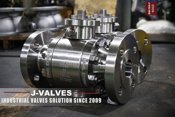
The J-VALVES DN50 PN63 trunnion ball valve is a two-piece forged stainless valve for European pipework: a 2 inch bore, EN 1092-1 PN63 flanges with a B2 raised face, an A182 F304L body split into a main body and one bolted end cap, and a ball carried between two trunnions instead of resting on its seats. Seats are soft, single piston effect is standard, and a drain plug lets the cavity be vented.
At two inches the trunnion is not there to carry load. A floating ball seals this size and class comfortably, because the force it hands to the seat is line pressure over a small bore. What a trunnion buys is different: the ball is supported, so torque stays low enough for a small actuator; the cavity can be vented to prove both seats in one operation; and the seats can be changed to double piston effect without touching the body. Specify it when the datasheet asks for one of those.
Most of these valves go onto European process pipework, where the flange on the pipe was ordered to EN dimensions and nothing else will bolt to it. One thing about the class first. PN63 is an EN 1092-1 step and it is not a step in API 6D, whose list runs PN 50, PN 64, PN 100. The two systems spell the nearest class with different digits, and that is where quotations go wrong.
Design and Construction
Two pieces, one joint. The main body carries both trunnions, both seat pockets and the stem; the end cap carries the second seat and closes the bore. That is the whole maintenance scope, and at DN50 the ball and both seats still come out through the cap. The arrow on the body shows which end it is. Put the cap downstream where the run allows, so with the valve closed the joint holds cavity pressure rather than line pressure.
Inside, both trunnions run in the main body. That is the arrangement up to and including four inch; from six inch the trunnions are carried in separate bearing blocks bored as a pair, because the ball outgrows what one body bore can hold accurately. At DN50 the simpler arrangement applies and it is the better one: upper and lower bores are machined in one set-up in one part, so stem axis and lower trunnion cannot disagree.
Seats are single piston effect as standard. Line pressure pushes the upstream seat onto the ball, the same pressure passes that seat into the cavity, and the cavity relieves back into the line, so nothing is trapped and thermal expansion between the seats cannot lock the valve. Double piston effect changes the boundary: both seats are pushed onto the ball, the cavity no longer relieves, and a relief device becomes part of the valve. Ask for it only when the datasheet specifies DIB-1.

Material Options
The specification is written in low-carbon austenitic grades throughout: A182 F304L for body and end cap, A351 CF3M for the ball, F304L for the stem, with F316L as the upgrade. That consistency is deliberate, and it is worth knowing what the L buys. F304 and F304L share a group in ASME B16.34, so they carry the same rating and the L grade does not raise the class. It lowers carbon, a welding argument, and lowers minimum yield, which the wall calculation pays for.
The ball is cast CF3M, the cast counterpart of 316L, so the wetted parts stay in one corrosion family. The seat is the real choice: RPTFE as standard, then PEEK, PPL, nylon and an F316L ring with a Stellite facing. The metal seat is the only route to the temperature the austenitic body allows; every polymer caps the valve below the body. One part is not austenitic, the 17-4PH stem, and in sour service its hardness is the question.
| Component | Standard Material | Optional Upgrade | Service Notes |
|---|---|---|---|
| Body and end cap | ASTM A182 F304L, forged | A182 F316L | Both halves from the same heat when the order allows |
| Ball | ASTM A351 CF3M with ENP | CF8M, hard chrome or Stellite overlay | Cast ball, L grade to match the body |
| Stem | ASTM A182 F304L | F316L, 17-4PH | 17-4PH is the one non-austenitic option; hardness limit applies in sour service |
| Seat rings | RPTFE | PEEK, PPL, nylon, F316L with Stellite facing | The seat sets the valve temperature, not the body |
| Body joint gasket | 316L spiral wound, flexible graphite filled | Flat gasket for water duty only | A ring joint is a flange facing, never a body joint gasket |
| Stem packing | PTFE V-ring set | Flexible graphite | Adjustable in service, not replaceable under pressure |
| Trunnion bearings | Metal-backed self-lubricating | Both trunnions housed in the main body at this size | |
| Bolting | A193 B8M with A194 8M nuts | B7 is offered where the piping class calls for carbon steel studs | |
| Anti-static device | Spring-loaded plunger, ball to stem to body | Resistance measured and recorded on every valve | |
| Cavity drain | NPT plug in the lower side of the body | Vent used to prove the seats | |
| Nameplate | Stainless steel | Size, class, material, heat number and serial |
Technical Specifications
Table 2 is the data sheet for this size and class. Every figure is either a tabulated standard value or a dimension taken from the signed general arrangement drawing, and where the drawing governs the table says so instead of quoting a number the drawing may contradict.
The bore is full port at 50 mm, which is the nominal size and not automatically the pipe bore: a DN50 pipe in a common wall is slightly larger inside, so a swab is sized to the valve bore, because the valve is the narrowest point in the run. Face to face follows EN 558, and when a valve is replaced it is the series rather than the size that matters, because another series moves the flange faces at the same DN.
| Item | Value |
|---|---|
| Nominal size | DN50 (NPS 2) |
| Pressure class | PN63 to EN 1092-1 |
| Body material | ASTM A182 F304L, forged |
| Ball | ASTM A351 CF3M with ENP |
| Seat | RPTFE |
| End connection | Flanged, EN 1092-1 Type 11 |
| Flange facing | Form B2 raised face, four bolt holes |
| Bore | Full port, 50 mm nominal |
| Face to face | EN 558, confirmed on the signed GA drawing |
| Design basis | API 6D and ASME B16.34 |
| Rating source | EN 1092-1 pressure-temperature table, body material group |
| Seat design | Single piston effect, self-relieving |
| Operator | Lever; worm gear or actuator mounting on request |
| Testing | Shell 1.5 times, seat 1.1 times, every valve |
| Temperature | The lower of body and seat, quoted with the seat |
Standards and Compliance
API 6D clause 7.2 lists the classes as PN 20, PN 50, PN 64, PN 100, PN 150, PN 250 and PN 420. There is no PN 63 in that list. EN 1092-1 runs 2.5, 6, 10, 16, 25, 40, 63, 100 and upward, and PN 63 is one of its steps. So this valve carries a European class that the American document does not name, and the nearest name it does have, PN 64, is a different class rather than a rounding of this one. Both statements are true at once, which is why they get treated as interchangeable.
Then look at the hardware. At DN50 the EN 1092-1 PN63 flange is 180 mm across on a 135 mm bolt circle, with four M20 holes and a 102 mm face. B16.5 at NPS 2 in Class 400 is 165.1 mm on a 127.0 mm circle with eight holes for 5/8 inch studs and a 91.9 mm face, and that class has no table of its own at this size: B16.5 uses the Class 600 figures up to NPS 3 1/2. The European flange is the larger of the two and carries half the bolts.
PN 63 is also where the raised face changes name. Table 2 of EN 1092-1 splits type B in two: B1 from PN 2.5 to PN 40, B2 from PN 63 to PN 100, with different roughness bands, Ra 3.2 to 12.5 against Ra 0.8 to 3.2. This valve is the first class at which B1 stops applying. A datasheet that says type B raised face without the digit is ambiguous at exactly this class, and a quotation priced from a PN16 drawing will have the wrong finish on it.
API 6D 7.2 also says where the numbers come from: a Class-rated valve takes its pressure-temperature values from ASME B16.34, a PN-rated valve from EN 1092-1, each for the material group of its parts. So this valve is read from the European tables although its design basis is the American document, and the 63 in the designation is a class, not an allowable at temperature. The austenitic group's flange-end ratings run to 1000 F; the minus 29 to plus 425 range in the header is the carbon steel envelope, not this valve's.
| Requirement | Standard | What J-VALVES Supplies |
|---|---|---|
| Pressure class | EN 1092-1 PN63 | Class marked on the nameplate and the drawing |
| Flange dimensions | EN 1092-1 Type 11, DN50 PN63 | 180 outside diameter, 135 bolt circle, four M20 holes, 102 face |
| Flange facing | EN 1092-1 Form B2 | Ra 0.8 to 3.2, the band that applies from PN 63 upward |
| Pressure-temperature rating | EN 1092-1, austenitic group | Read at design temperature, not at the class number |
| Body design | ASME B16.34 | Wall, trunnion supports, gland |
| Product standard | API 6D | Design, cavity relief, marking |
| Pressure testing | API 6D | Shell 1.5 times, seat 1.1 times by cavity pressurisation |
| Fire test | API 607 and ISO 10497 | Certificate issued with the serial |
| Anti-static | API 6D | Continuity measured on every valve |
| Marking | API 6D and EN 1092-1 | Nameplate cross-referenced to the test record |
| Certification | EN 10204 3.1 | Mill certificates, dimensional report, GA drawing |
Manufacturing Process
The body begins as a forging, and the two halves are cut from the same heat whenever the order allows, so the joint faces respond alike to machining and to temperature. They are match marked, then the faces are machined with the pair bolted together: flat against each other rather than each flat on its own, and the bolt holes drilled in line. That decision decides whether the valve still seals after it has been opened in the field.
The trunnion bores are the other critical pair. Upper and lower are machined in one set-up in the main body, so the stem axis and the lower trunnion share a reference that never crosses the body joint. The ball is lapped, the seat pockets cut to the ring that will sit in them, and the assembly cleaned and greased in a closed area before the cap goes on.

Quality Control and Testing
Eight checks stand between the forging and the crate. Three cannot be corrected afterwards: certificate and heat traceability, forging soundness by visual and ultrasonic examination, and the machined geometry of joint faces, trunnion bores and flanges. Three are assembly: seat squeeze, gland load and dry stem torque. The last two are the pressure tests and the marks, with the serial carried across the record, the certificate and the nameplate.
Pressure testing is to API 6D: shell at 1.5 times the rated pressure, seat at 1.1 times, and on a trunnion valve the seat test is run by pressurising the cavity, which proves both seats in one operation and is why double block and bleed is a procedure here rather than a feature somebody added. Soft seats are held to no visible leakage. Anti-static resistance is measured on every valve.
| Step | What Is Checked | Standard or Acceptance |
|---|---|---|
| 1 | Material certificate and heat traceability | EN 10204 3.1, against the grade on the drawing |
| 2 | Forging soundness | Visual and ultrasonic, no relevant indications |
| 3 | Joint faces, pair match marked | Flatness and finish, checked as a pair |
| 4 | Trunnion bore alignment, upper to lower | Bored in one set-up, verified on the assembly |
| 5 | Ball roundness and surface finish | Against the drawing before plating |
| 6 | Seat squeeze and spring load | Set to the seat drawing for the size |
| 7 | Gland load and dry stem torque | Recorded on the test sheet |
| 8 | Shell test | 1.5 times rated pressure, API 6D |
| 9 | Seat test by cavity pressurisation | 1.1 times, both seats in one operation |
| 10 | Anti-static continuity | Measured and recorded on every valve |
| 11 | Marking and documentation | Serial carried across record, certificate and nameplate |

Applications and Industry Service
The natural home is European process pipework at moderate pressure: chemical and dosing lines, solvent circuits, pharmaceutical and food-grade water in F304L, gas distribution upstream of a regulator, and OEM skids drawn to EN flanges. In those lines the valve is cycled occasionally, the medium is clean, and what matters is a flange that bolts up, a seat that does not weep after a year, and a cavity that can be vented.
It is worth being clear about where this valve is the wrong choice. A line cycled several times a day wears a soft seat and should have a metal one. A buried or subsea line should not have a body joint at all. Sour service needs NACE bolting and a stem inside the hardness limit, which 17-4PH may not meet. A line that will be pigged needs the bore checked against the tool, not the pipe.
Installation, Operation and Maintenance
Fit it with the arrow downstream and the cap end on the low-pressure side where the run allows. Use a gasket made for the B2 face: the American raised face stands 6.4 mm proud at Class 400 and 600, while the B2 face is a shallower step, so a gasket ordered for one will not seat in the other. Bring the studs up in a cross pattern in three passes and check the faces are parallel first.
Nothing on a trunnion valve can be replaced under pressure except one part. The stem is retained by the body, so with the cavity vented the packing can be adjusted and the upper stem O-ring changed while the line stays live; that is the single item, and the clear advantage this design has over a floating valve. The body joint is a boundary: isolate, depressurise and drain before the cap comes off.
How to Specify and Order
Six answers settle the order: size and class, the facing form, which should be written as B2 rather than type B, seat material against the actual temperature, single or double piston effect, the operator and its mounting interface, and the test and certification package. If the line is sour, or the valve will be automated, say so at enquiry: bolting grade and mounting flange are decided before the body is machined.
Ask for the documents with the quotation: EN 10204 3.1 certificates for body, ball and stem with heat numbers, the signed general arrangement drawing with the face-to-face dimension on it, the pressure test record by serial, the fire certificate and the anti-static readings. A PN63 valve bought without the facing form and the rating table is one that will be argued about at inspection.
FAQ
Q: Is PN63 the same as Class 400?
A: No, and the difference is in the number itself. API 6D clause 7.2 lists its classes as PN 20, PN 50, PN 64, PN 100, PN 150, PN 250 and PN 420, so PN 64 is the designation for Class 400 and PN 63 is not a class in that document at all. PN 63 is an EN 1092-1 step. At DN50 the European flange is 180 mm across on a 135 mm bolt circle with four M20 holes and a 102 mm face, while B16.5 at NPS 2 in Class 400 is 165.1 mm on a 127.0 mm circle with eight 5/8 inch holes and a 91.9 mm face, and at that size Class 400 has no table of its own because B16.5 uses the Class 600 figures up to NPS 3 1/2. Order by the flange that is on the pipe, not by the nearest number.
Q: Why fit a trunnion valve at two inches?
A: Not for load. The force a ball hands to its seat is line pressure over the bore area, and at DN50 that is small enough for a floating valve to seal comfortably. A trunnion is bought here for three other reasons: the ball is supported, so the torque stays low and a small actuator will cycle it; the cavity can be vented, which is how both seats are proved in one operation; and the seat design can be changed to double piston effect for DIB-1 without changing the body. If the datasheet asks for none of those, a floating valve does the same job with fewer parts.
Q: Can the upper stem seal be replaced with the line under pressure?
A: That one item, yes, and it is the clear advantage of a trunnion over a floating valve. The stem is retained by the body, so with the body cavity vented to atmosphere the packing can be adjusted and the upper stem O-ring changed while the line stays live. It does not extend to the body joint: the joint between main body and end cap is a pressure boundary, so the line must be isolated, depressurised and drained before the studs come out. The valve can stay in the pipe; the pipe cannot stay under pressure.
Q: Which raised face applies at PN63, B1 or B2?
A: B2. Table 2 of EN 1092-1 splits the type B raised face in two: B1 is used from PN 2.5 to PN 40, B2 from PN 63 to PN 100, and they carry different roughness bands, Ra 3.2 to 12.5 for B1 against Ra 0.8 to 3.2 for B2. PN 63 is the first class at which B1 no longer applies, so a datasheet that says type B raised face without the digit is ambiguous at exactly this class. A quotation priced from a PN16 drawing will carry the wrong finish, and the face is machined before anyone notices.


Hot Products


News
Ball Valves in A Kraft Pulp Mill: Black Liquor, Green Liquor And The Cost of Choosing The Alloy by Habit
White liquor at pH 14 cracks carbon steel welds, black liquor sets solid below 100 C, green liquor dregs grind seats: alloy choice and torque in a kraft mill.
Read More
Slug Flow And Ball Valves: What Actually Arrives At The Seat
A slug is liquid mass with momentum, not a pressure spike. What changes at the seat, in the cavity and at the actuator when liquid reaches a ball valve.
Read More
Ball Valves in Direct Lithium Extraction: PH 1 Eluate, Gypsum Scale And 438,000 Cycles in Twenty-Five Years
Direct lithium extraction swings valves from pH 1 eluate to pH 12 caustic, 48 column switches a day and gypsum scale. Materials, seats and torque.
Read More
Ball Valves in Geothermal Brine: Silica Scale, Chloride Cracking And The Cooling Trap
Why geothermal brine destroys ball valves: retrograde silica scale, calcite at the flash point, chloride cracking above 60 C and the 250 C seat limit.
Read More