


CHINA J-VALVES Offers Various High-quality I ndustrial Ball Valves
J-VALVES, a distinguished professional ball valve manufacturer rooted in China, takes pride in its extensive product portfolio. Our offerings span a wide range, including trunnion-mounted ball valves, floating ball valves, high-temperature ball valves, high-pressure ball valves, metal-sealed ball valves, ultra-low temperature ball valves, DBB ball valves, Three-way And Four-way Ball Valve, and fully welded ball valves. Each product is a testament to our commitment to precision engineering and reliable performance. Meticulously crafted, they are designed to not only meet but exceed the most stringent industrial demands, ensuring stable operation even under extreme conditions. This enables us to provide our clients with high-value services and makes our valves widely sought-after in industries.
Product Category
Contact Us


-
J-VALVES-H44W
-
J-VALVES
Overview of the J-VALVES 10 Inch Class 300 Top Entry Trunnion Ball Valve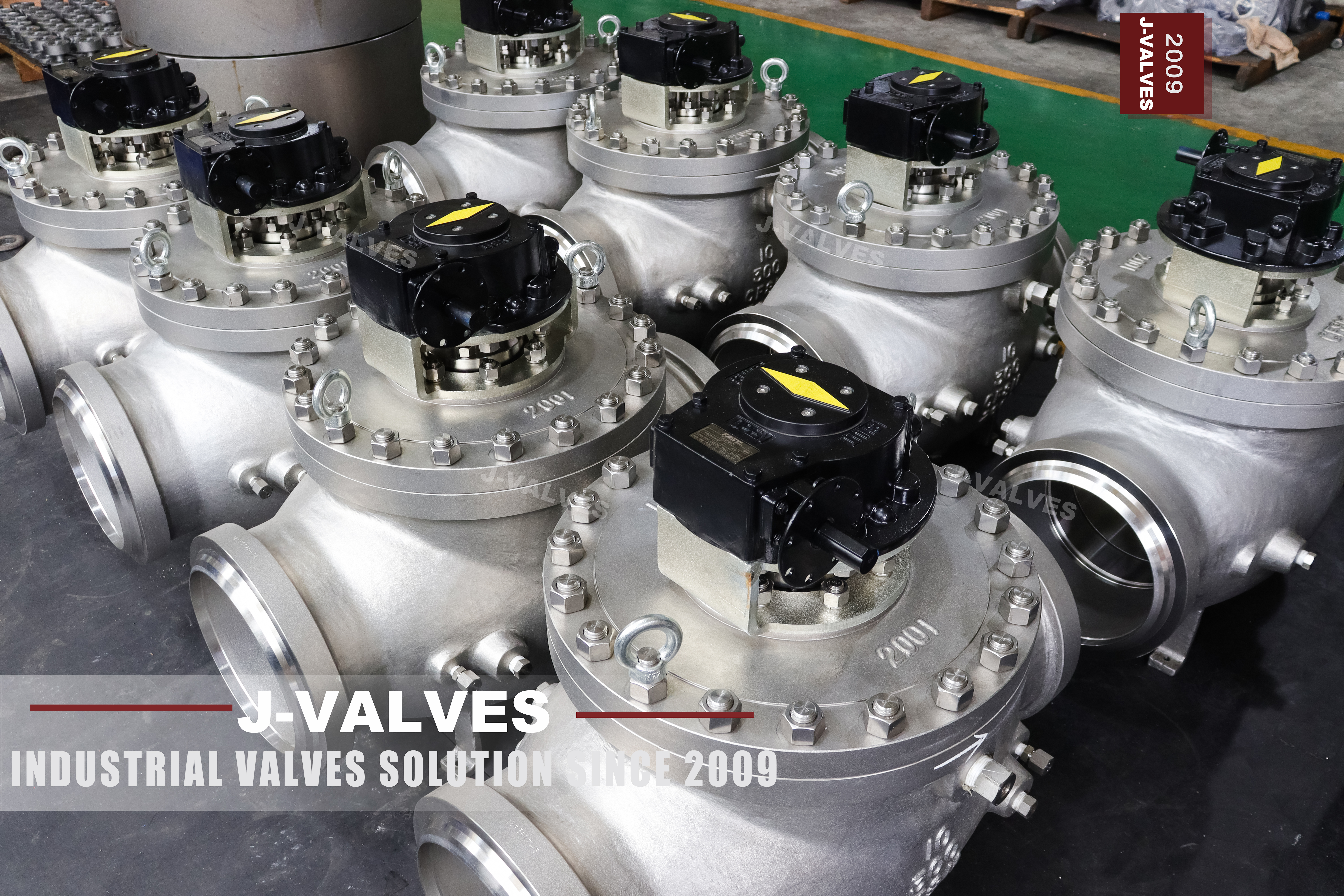
The J-VALVES 10 inch top entry trunnion ball valve is a DN250, ASME Class 300 isolation valve on a one-piece body with a bolted bonnet on top. API 6D records Class 300 as PN50, so a project may order it either way. The body is ASTM A351 CF8M, the ball runs on two trunnions in machined bearing blocks, the seats are spring loaded, and the ends are raised face or ring joint flanges to ASME B16.5.
At DN250 a side entry body needs either two body joints or one joint plus room to swing the ball and seats sideways, and either way the pipe must be broken to reach a seat. The top entry body is a single casting, so the through passage has no bolted seam at all. The one pressure joint left is the bonnet, and it sits outside the flow path.
Ten inch Class 300 lines are usually headers, terminal manifolds, tank farm piping, chemical transfer and produced water. In those systems the valve is a block valve, open or closed, few cycles, and the reason for paying for top entry is that the line cannot be drained and opened whenever a seat needs looking at.
Design and Construction
The bonnet opening has to pass the ball, so it is wider than the bore. That explains most of the arrangement: the gasket at the top becomes the largest diameter seal on the valve, and the stud ring around it becomes the most heavily loaded bolting on the unit. What the arrangement buys is a joint above the pipe centre line, where a fitter can reach it.
From 6 inch upward the ball is held by an upper and a lower trunnion, and both run in bearing blocks machined as a pair rather than as separate parts. On a top entry valve the lower block sits in the body and the upper block is carried by the bonnet. The bonnet therefore locates the upper bearing and, with it, the stem axis.
The stem is separate from the ball and is not loaded by the side thrust that line pressure puts on the ball, because the trunnions carry that load. On this design the stem is retained by the bonnet, so the bonnet studs hold both the pressure boundary and the stem. The anti-blowout feature depends on that joint staying made.
Both seat rings are spring loaded against the ball and pressure assisted: line pressure behind a ring adds to the spring load and pushes the ring onto the ball. Single piston effect is standard, and its defining behaviour is that cavity pressure pushes the upstream ring away from the ball, so an overpressure escapes into the line. Double piston effect is the option, giving two barriers and no way out of the cavity.

Material Options
CF8M is chosen for the fluid, not for the rating. ASME B16.34 puts A351 CF8M in material group 2.2 and A216 WCB in group 1.1, and at Class 300 the two tables do not rank the way buyers expect: at 38 C the group 2.2 figure is 720 psi and the carbon steel figure is 740 psi. The stainless body is rated marginally lower, and what it buys is corrosion resistance.
| Component | Standard Material | Optional Upgrade | Service Notes |
|---|---|---|---|
| Body | ASTM A351 CF8M | A182 F316 forged, CF3M | One-piece top entry casting, bonnet flange cored in |
| Bonnet | ASTM A351 CF8M | A182 F316 | Carries the upper trunnion bearing block |
| Ball | A182 F316 with ENP | Hard chrome, tungsten carbide HVOF | Trunnion mounted, two bearing blocks at this size |
| Stem | 17-4PH | A182 F316 | Separate from the ball, retained by the bonnet |
| Trunnion | 17-4PH | A182 F316 with hardfacing | Runs in metal backed self-lubricating bearings |
| Seat ring | A182 F316 | Weld overlay on the seating face | Spring loaded, free to move along the valve axis |
| Soft seat insert | PTFE | RPTFE, PPL, PEEK | Sets the top temperature of the standard build |
| Bonnet gasket | 316L spiral wound, graphite filler | Metal ring joint facing | Largest diameter seal on the valve |
| Stem packing | Flexible graphite, Inconel wire | Live loaded gland | Graphite stack holds after soft packing burns |
| Bonnet bolting | A193 B8M with A194 8M nuts | B7 for moderate non-sour duty | Holds the pressure boundary and the stem |
Temperature is two limits and not one. The body figure is the range number, minus 29 to plus 425 C. The seat is the lower of the two and it governs the valve as sold: PTFE and RPTFE are listed to 180 C, PPL to 280 C, PEEK to 260 C, and a metal seat with a graphite insert is the only way to reach the body limit. Cold duty is a separate specification.
Where the design temperature runs toward the top of the range, the stem grade deserves a question, because 17-4PH is chosen for strength at moderate temperature and its allowable stress falls away well before the body limit does. In sour service the same part is hardness controlled to NACE MR0175 or replaced with Inconel 718.
Technical Specifications
The table states the anchor of this page, one size and one class, taken from the customer datasheet rather than picked out of the series range. Anything that depends on the bore, the facing or the operator belongs on the signed general arrangement drawing.
| Item | Value |
|---|---|
| Size | 10 inch (DN250) |
| Pressure class | ASME Class 300, recorded as PN50 under API 6D clause 7.2 |
| Body style | One-piece body, top entry, bolted bonnet |
| Body material | ASTM A351 CF8M |
| Ball and trunnion | A182 F316 with ENP, two machined bearing blocks |
| Seat | Spring loaded, single piston effect standard, double on request |
| Bore | Full bore or reduced bore, per API 6D Table 1 |
| End connection | Flanged RF or RTJ to ASME B16.5, butt weld to B16.25 on request |
| Flange drilling | B16.5 Class 300 NPS 10: 444.5 mm outside diameter, 387.4 mm bolt circle, 16 bolts of 1 inch, raised face 323.9 mm |
| Face to face | Per API 6D and ASME B16.10, confirmed on the signed drawing |
| Operation | Worm gear standard at this bore, pneumatic, electric or hydraulic on request |
| Temperature | Minus 29 to plus 425 C, limited by the seat supplied |
Standards and Compliance
The governing document is API 6D, published as ISO 14313. It covers pipeline valves from NPS 2 upward at Class 150 to 2500, and it is the reason a valve at this bore is trunnion mounted at all: with the ball supported top and bottom, the stem carries torque rather than thrust. The 2014 edition added quality levels, QSL-1 to QSL-4, raising examination and documentation.
PN50 needs its own paragraph, because it is where metric and inch projects part company. API 6D clause 7.2 records Class 300 as PN50, so PN50 on a nameplate is correct. EN 1092-1, however, steps from PN40 to PN63 and has no PN50 seat, so a PN50 flange does not exist. At DN250 the nearest two are almost the same size and still will not mate: the EN PN40 part is 450 mm outside diameter on a 385 mm bolt circle with 12 M30 bolts, the ASME Class 300 part is 444.5 mm on 387.4 mm with 16 bolts of 1 inch. A flange is identified by its drilling, not its diameter.
Testing follows the same logic. The shell test runs at 1.5 times the rated pressure, and the seat test pressurizes the body cavity rather than filling one side of the line, which proves both seats in a single pass and doubles as the double block and bleed check. Fire performance is certified to API 607, API 6FA and ISO 10497.
One standard should not be named beside API 6D here, and that is API 608. The two are separate documents and neither contains the other. API 608 is a product standard for metal ball valves in general process service, and naming both leaves the test regime ambiguous, because they prescribe different seat test methods and different documentation. For a trunnion valve at DN250 the answer is API 6D alone.
| Requirement | Standard | What J-VALVES Supplies |
|---|---|---|
| Design and manufacture | API 6D / ISO 14313 | Compliance statement with the edition quoted |
| Pressure temperature rating | ASME B16.34, group 2.2 | Rating read at design temperature, not at ambient |
| Flange dimensions | ASME B16.5, NPS 10 Class 300 | 444.5 mm, bolt circle 387.4 mm, 16 bolts of 1 inch |
| Pressure test | API 6D, API 598 on request | Shell at 1.5 times rating, seat by cavity pressurization |
| Fire test | API 607, API 6FA, ISO 10497 | Certificate carrying the valve serial number |
| Fugitive emissions | ISO 15848-1 | Graphite packing stack, report on request |
| Sour service | NACE MR0175 / ISO 15156 | Hardness controlled trim, Inconel 718 where needed |
| Material certification | EN 10204 3.1 | Heat number traced to each pressure retaining part |
Manufacturing Process
The body starts as a CF8M casting poured from a pattern in which the bonnet flange and the seat pockets are cored rather than drilled. After solution annealing every heat is checked by positive material identification before release to machining, because a mixed 316 and 316L heat is the one error no later inspection will catch. The bonnet flange and the body face are machined in one set-up.
The ball is ground, then coated. ENP goes on after grinding and the thickness is checked on the sealing band rather than the bore, because that is where seat contact happens. Seat rings are lapped against their own ball rather than a master, so the pair stays matched. Where duty calls for it, the seat pockets and stem sealing area can be weld overlaid with a nickel alloy.
Assembly is done with the body upside down, ball and seats lowered in, then the bonnet set down over the upper bearing block and the studs brought up in a cross pattern in at least three passes. The gear operator is mounted last, and the open and closed stops are set on the gearbox rather than on the valve.

Quality Control and Testing
Eight checks stand between the casting and the crate. The first three concern what cannot be corrected later: casting soundness, the flatness of the bonnet joint, and the roundness and finish of the ball. The middle three are the fits: seat squeeze, bearing clearance on both blocks, and stem torque dry. The last two are the pressure tests and the final marks.
| Step | What Is Checked | Standard or Acceptance |
|---|---|---|
| 1 | Heat chemistry and material identification | A351 CF8M, every pressure part traced to its heat |
| 2 | Casting soundness at bonnet flange and seat pockets | Radiography or ultrasonic, dye penetrant on machined faces |
| 3 | Bonnet joint flatness and finish | Checked on a surface plate before assembly |
| 4 | Ball roundness, coating thickness, finish | Measured on the sealing band, not on the bore |
| 5 | Seat squeeze and spring load | Ring free to move, spring load within the drawing |
| 6 | Bearing clearance in both trunnion blocks | Upper and lower blocks matched to their own bores |
| 7 | Stem torque, dry | Recorded per serial number, supplied with the report |
| 8 | Shell and seat pressure test | Shell 1.5 times rating, seat by cavity to API 6D |
The records are the part buyers underestimate. Every valve leaves with a shell and seat report carrying its serial number, a material certificate to EN 10204 3.1, and a torque figure for that individual unit rather than a catalogue value. This matters more here than on a side entry valve, because the bonnet joint is the single seam that has to hold.

Applications and Industry Service
The natural home is a ten inch header that cannot be opened on demand: tank farm and terminal manifolds, transfer lines between storage and process, produced water headers, and chemical lines that will not tolerate a carbon steel body. In all of these the valve sits closed for long periods, opens for a transfer, and the maintenance question is whether the line can be taken out of service.
Class 300 at DN250 is a moderate pressure duty. It is high enough that a floating ball would be carrying a load the seats should not take, and low enough that the body wall and flange ring are not the constraint. CF8M adds the chloride and dilute acid resistance that brackish cooling water and produced water need. Where the medium carries abrasive solids, the metal seat is the specification.
There are duties where this valve is the wrong answer, and saying so is part of the specification. Buried service is one: the bonnet has to face up and the cartridge has to be lifted out, so a buried line needs an extended stem and a valve chamber. Subsea, fast cycling actuator duty, and lines where a fully welded body is mandated all point elsewhere.
Installation, Operation and Maintenance
Install with the bonnet up and the stem within the angle the manufacturer allows, because the cartridge is lifted vertically out of the body. On a ten inch valve that lift needs headroom and a crane, and the rigging plan belongs in the installation method statement rather than the maintenance procedure. Support the valve on its own saddles so the bonnet studs carry no pipe load.
The double block and bleed procedure is worth understanding rather than copying. Close the valve, open the cavity drain and watch. With single piston effect seats, venting the cavity unloads the downstream seat, so the vent proves the upstream seat; repeat with the pressure on the other side. What single piston effect cannot give is double isolation in service; that is DIB-1, and it needs double piston effect seats, which have no self relief and need an external cavity relief device.
What can be done with the line live is narrow and should be stated narrowly. With the cavity vented, the gland can be adjusted and the upper stem O-ring replaced, because the stem is retained by the bonnet. Nothing else is online work. The bonnet joint is a pressure boundary, so opening it means isolating, depressurizing, draining and purging first, then fitting a new gasket.
How to Specify and Order
Six questions decide the valve, and each changes something that cannot be changed after casting. Size and class, and whether the nameplate reads Class 300 or PN50. Full bore or reduced bore, since a reduced bore changes the ball, the seats and the cavity but not the flange. Single or double piston effect seats, and if double, whether a cavity relief device is fitted. Body and trim material, and whether sour service applies. End connection and facing. Operator.
Then the documents. Ask for the general arrangement drawing with the face to face dimension and the flange drilling marked on it, the material certificate to EN 10204 3.1, the shell and seat report with the serial number, the fire certificate, and the individual torque record. On a top entry valve, add the bonnet bolting procedure and the gasket part number. Those two are what a maintenance team needs five years from now.
FAQ
Q: Can a top entry ball valve be serviced while the line is under pressure?
A: No, and this is the single most repeated error in top entry marketing. What the design gives you is access without disturbing the pipe flanges: the bonnet comes off the top and the ball cartridge lifts out upward, so the pipe is never cut, spread or re-gasketed. The bonnet joint is still a pressure boundary. It has to be isolated, depressurized, drained and purged before a single stud is released. The one exception is narrow and worth knowing: with the body cavity vented to atmosphere, the gland can be adjusted and the upper stem O-ring replaced, because the stem is retained by the bonnet and stays captured. Nothing else on this valve is live work.
Q: Is PN50 the same as Class 300?
A: Yes as a valve designation, no as a flange. API 6D clause 7.2 records Class 300 as PN50, so a nameplate or datasheet carrying PN50 is correct and can be quoted. EN 1092-1 does not have a PN50 step at all: the ratings run PN25, PN40, PN63, and a PN50 seat does not exist. At DN250 the mistake is easy to make because the nearest metric flange sits right next to the inch one on paper. The EN PN40 part is 450 mm outside diameter on a 385 mm bolt circle with 12 M30 bolts; the ASME Class 300 part is 444.5 mm outside diameter on a 387.4 mm bolt circle with 16 bolts of 1 inch. A flange is identified by its drilling, not by its diameter.
Q: Does a stainless body give a higher pressure rating?
A: No, it is marginally lower at this class, and that surprises buyers who treat CF8M as an upgrade across the board. ASME B16.34 puts A351 CF8M in material group 2.2 and carbon steel in group 1.1, and at Class 300 the group 2.2 value at 38 C is 720 psi against 740 psi for the carbon steel group. Stainless is bought for the fluid, not for the class: chloride resistance, dilute acids, product purity, and a wetted side that needs no coating. What actually changes the usable range is a different material group, low temperature steel at the cold end or an alloy grade above the carbon steel ceiling, not a switch from carbon to 316.
Q: What is the difference between double block and bleed and double isolation?
A: One is a procedure, the other is a built-in capability, and the original page ran them together. Double block and bleed is a test: close the valve, open the cavity drain, and see which seat holds. With single piston effect seats, venting the cavity unloads the downstream seat, so the vent proves the upstream seat only; repeat with the pressure on the other side and the second seat is proven. That is a valid DBB test. Double isolation, DIB-1, is different: both seats hold at once with the cavity vented, and that requires double piston effect seats. DPE seats have no self relief, so the cavity then needs an external relief device, which is a pressure boundary connection that must be specified rather than assumed.


Hot Products


News
Ball Valves in A Kraft Pulp Mill: Black Liquor, Green Liquor And The Cost of Choosing The Alloy by Habit
White liquor at pH 14 cracks carbon steel welds, black liquor sets solid below 100 C, green liquor dregs grind seats: alloy choice and torque in a kraft mill.
Read More
Slug Flow And Ball Valves: What Actually Arrives At The Seat
A slug is liquid mass with momentum, not a pressure spike. What changes at the seat, in the cavity and at the actuator when liquid reaches a ball valve.
Read More
Ball Valves in Direct Lithium Extraction: PH 1 Eluate, Gypsum Scale And 438,000 Cycles in Twenty-Five Years
Direct lithium extraction swings valves from pH 1 eluate to pH 12 caustic, 48 column switches a day and gypsum scale. Materials, seats and torque.
Read More
Ball Valves in Geothermal Brine: Silica Scale, Chloride Cracking And The Cooling Trap
Why geothermal brine destroys ball valves: retrograde silica scale, calcite at the flash point, chloride cracking above 60 C and the 250 C seat limit.
Read More