
CHINA J-VALVES Offers Various High-quality I ndustrial Ball Valves
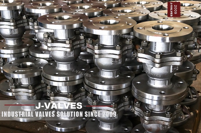
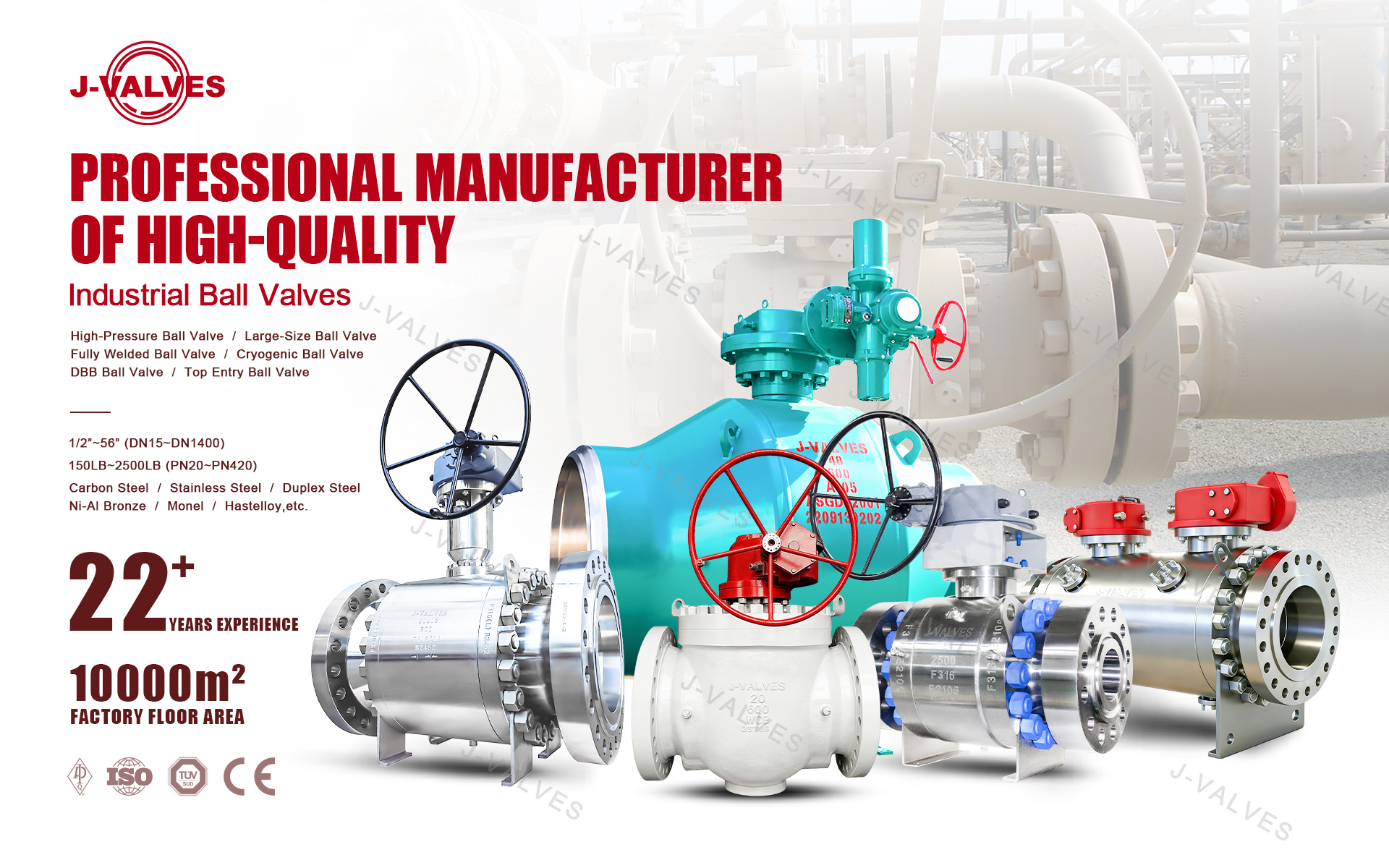
J-VALVES, a distinguished professional ball valve manufacturer rooted in China, takes pride in its extensive product portfolio. Our offerings span a wide range, including trunnion-mounted ball valves, floating ball valves, high-temperature ball valves, high-pressure ball valves, metal-sealed ball valves, ultra-low temperature ball valves, DBB ball valves, Three-way And Four-way Ball Valve, and fully welded ball valves. Each product is a testament to our commitment to precision engineering and reliable performance. Meticulously crafted, they are designed to not only meet but exceed the most stringent industrial demands, ensuring stable operation even under extreme conditions. This enables us to provide our clients with high-value services and makes our valves widely sought-after in industries.
Product Category
Contact Us


Pressure Class: ASME Class 150 to 1500 / PN20 to PN250
Body Style: One piece body, bolted top entry bonnet
Body Material: WCB, LCC, CF8M, CF8, F51, F316
Ball: CF8M or F316, hard chrome or ENP plated
Seat :Cartridge type, PTFE / PEEK / Stellite, spring loaded
Seat Design: Double piston effect, or single piston self-relieving
Bonnet Gasket: 316L spiral wound graphite; ring joint above Class 900
Stem: F316 or 17-4PH, blow-out proof
Packing: Flexible graphite, live loaded option
End Connection: Flanged RF/RTJ, butt weld, socket weld
Design Standard: API 6D, API 608, ASME B16.34, ISO 15848-1
Test Standard: API 598, API 607, API 6FA
-
Q347F-300LB R
-
J-VALVES
A top entry ball valve is a quarter-turn isolation valve whose one-piece body carries a bolted bonnet directly above the ball, so the ball, both seat cartridges and every sealing part lift out through that opening while the valve stays bolted in the pipeline. Nothing is cut or re-welded, and the pipe supports are never touched. The repair is a bonnet job, not a piping job.
J-VALVES manufactures this style from 2 inch to 36 inch in ASME Class 150 to 1500 at its works in Wenzhou, Zhejiang, in WCB, LCC, CF8M, CF8, F51 and F316. Buyers are pipeline operators, slurry and catalyst plants, power station engineers and offshore packagers who have already paid once for a valve that could not be repaired where it stands.

What Top Entry Solves
The problem is not sealing but access. A side entry valve is built through the end of the body, so the ball travels in the same direction as the pipe, and the part that must come off to reach it is bolted to the line. Every seat change starts by breaking a joint designed to stay closed for twenty years.
A top entry ball valve inverts that geometry. The bonnet is a cover on a vertical opening sized to pass the ball and both cartridges, and the body never separates. On a 12 inch Class 600 valve the bonnet is 14 studs and a 180 kg cover: a morning with a chain block, not a pipe fitter's day with a welder on standby.
Construction | Typical size | Pipe work to change seats | Man-hours on site | Crane |
|---|---|---|---|---|
Three-piece side entry | 2-8 inch, Class 150-600 | Break both body joints, spread the line 10-15 mm | 6-10 | Not normally |
Two-piece side entry | 2-24 inch | Break one pipe flange, lift the end closure | 8-16 | Above 12 inch |
Top entry | 2-36 inch | None | 4-8 | Above 16 inch, bonnet only |
Fully welded | 8-48 inch | Cut out, re-weld, radiograph, purge, hydro | 40-72 | Yes |
The table assumes one valve, two fitters and a helper, and excludes isolation, which costs the same for all four. The saving is six to ten hours on the valve, plus no scaffolding, no insulation remade, no weld procedure and no radiography.
What it does not remove is the shutdown. The line still has to be isolated, drained, vented and proved gas-free, and on a single-stream plant that means a bypass or an outage. In-line maintainable means no pipe work, not a running pump.
One Piece Body and the Bonnet Joint
A top entry ball valve body is one piece from flange to flange. The only gasketed pressure joint is the bonnet, on a horizontal face above the bore where a fitter can reach it. Axial thrust, bending and vibration run through the body wall as a continuous ring and never cross that joint.
Type | Gasketed body joints | Stem seals | Pipe connections | Paths to atmosphere | Joint position |
|---|---|---|---|---|---|
Two-piece side entry | 1 | 1 | 2 flanges | 4 | Horizontal, in the line |
Three-piece side entry | 2 | 1 | 2 flanges | 5 | Horizontal, both in the line |
Top entry | 1 | 1 | 2 flanges | 4 | Horizontal, above the bore |
Fully welded | 0 | 1 | 2 welds | 3 | No gasketed body joint |
A gasketed joint is a maintained item and a weld is not. A three-piece body at 12 inch carries two large spiral wound gaskets in the pipe axis, where thermal movement works them in shear. The bonnet gasket sits perpendicular to that movement: it sees pressure and bolt load, not pipe strain.
The price is metal. The top opening must clear the ball, so the cavity is wider than the bore needs, and the bonnet flange holds full bore pressure across a diameter larger than the pipe. A 20 inch Class 600 body weighs about 1.9 t against 1.5 t side entry.
The Bonnet Gasket and Live Loading
The bonnet joint of a top entry ball valve is a bolted flange in a hot, cycling line, and it is where a repairable valve most often becomes a leaker. Gasket choice follows temperature and class.
Gasket | Construction | Class / temperature | Seating stress | Reuse after a break |
|---|---|---|---|---|
Spiral wound | 316L windings, graphite filler, inner and outer ring, 4.5 mm | 150-900, -29 to 450°C | 70-90 MPa | No, replace every time |
Ring joint | Octagonal soft iron or 316 ring in a machined groove | 900-1500, to 550°C | 120-160 MPa | No, groove finish 1.6 µm Ra |
Graphite laminate | Flexible graphite sheet or corrugated, 1.5-3 mm | 150-600, to 450°C | 40-60 MPa | Only if intact |
PTFE filled | PTFE with glass or carbon filler | 150-300, -29 to 120°C | 25-35 MPa | No |
Bolt preload is set, not guessed. For A193 B7 studs at 725 MPa yield, the target is 50 to 60 percent of yield, 380 to 420 MPa, which with molybdenum disulphide lubrication and a friction factor near 0.16 gives about 390 Nm for M20, 680 Nm for M24 and 1350 Nm for M30. A dry stud at the same torque gives 30 percent less clamp load, the usual reason a joint weeps at first heat-up.
Thermal cycling takes preload away. The flange, gasket and studs expand at different rates, and the gasket consolidates 0.05 to 0.15 mm in the first cycles. Disc springs, two or three in series per stud, store 8 to 12 kN each over 0.4 mm and hold gasket stress above 40 MPa. Without them a 350°C line loses about 15 percent of preload in ten cycles.
Leaks read by direction. A gasket failure wets the stud circle and runs down the bonnet; a packing failure runs down the stem and drips from the gland nut. Telling them apart saves a gasket set and a shift.
Seat Cartridge Design
The seat is not a ring pressed into a pocket but a cartridge: a metal carrier holding the insert, a spring pack behind it, a secondary seal on the outside diameter and an anti-extrusion ring, set to height before it goes in. It drops in from above, is held by a retainer and withdraws as one piece. The two cartridges also centre the ball, and above 12 inch a bottom trunnion pin carries its weight.
The spring pack gives 0.15 to 0.25 MPa of initial seat stress, enough for bubble-tight closure at low line pressure, and keeps the seat against the ball during pressure reversal and contraction. Coil springs in individual pockets are used above 8 inch, because a wave washer cannot spread stress evenly around a 300 mm seat.
Most top entry ball valves here use double piston effect seats: line pressure upstream and cavity pressure behind both push the seat toward the ball, so the valve seals either way and gives true double block and bleed. The trade is that a liquid-filled cavity which warms has nowhere to expand. Above about 40°C of expected swing we supply single piston seats with a self-relieving path, or a cavity relief valve, and mark it on the drawing.
The secondary seal is FKM or FFKM to 200°C and graphite above, with metal-to-metal backup for fire. It keeps the valve tight when grit scores the insert, and it is replaceable with the cartridge.
Disassembly and Reassembly Sequence
The sequence for a repairable ball valve, taken from the manual, assumes the line is isolated and the valve is at ambient.
Depressurise both sides, drain the cavity through the drain plug, vent and prove gas-free. Record zero pressure before touching a stud.
Remove the actuator or gearbox and the coupling, and support the stem so the thrust bearing is not loaded.
Mark bonnet to body orientation, and number the studs clockwise from a reference.
Crack the nuts in reverse order, one flat at a time, in three passes; never release one side fully while the other is tight.
Fit lifting eyes and take the weight on a chain block; a 24 inch Class 600 bonnet weighs 180 to 260 kg.
Lift vertically. If it resists, the spigot is dry or the gasket has bonded; use the jacking slots, never a chisel on the gasket face.
Withdraw the ball on a soft sling and inspect for scoring, ovality and chrome or ENP damage.
Pull both cartridges, note which side each came from, and check spring free length, insert height and O-ring condition against the drawing.
Clean the faces and pockets, fit new cartridges and a new gasket, and confirm the cartridge stand-out height.
Tighten in three stages, 30, 60 and 100 percent of torque, criss-cross: with 12 studs numbered clockwise the order is 1, 7, 4, 10, 2, 8, 5, 11, 3, 9, 6, 12. Operate twice, then repeat the seat and joint test.
Two details decide whether the job lasts: the gasket must be new, because a compressed spiral wound gasket has no recovery, and the studs must be lubricated and hand-tight before the wrench, or a cross-threaded stud strips at 680 Nm.
Side Entry, Top Entry or Fully Welded
The three do the same hydraulic job. The top entry trunnion ball valve is the one bought when the valve will be opened again.
Construction | Leak paths | In-line repair | Cost index | Largest size | Lead time | Typical duty |
|---|---|---|---|---|---|---|
Two-piece side entry | 4 | No, one pipe flange must break | 1.00 | 24 inch | 4-6 weeks | Clean fluid, low cycle count |
Three-piece side entry | 5 | Partly, line must spread | 1.05-1.20 | 8 inch | 4-6 weeks | Small bore, workshop service |
Top entry | 4, one accessible | Yes, bonnet only | 1.35-1.70 | 36 inch | 6-8 weeks | Slurry, catalyst, cycling |
Fully welded | 3 | No, cut and re-weld | 1.15-1.40 | 48 inch | 6-8 weeks | Buried or unapproachable |
Top entry, weld ends | 3 | Trim only | 1.45-1.80 | 36 inch | 7-8 weeks | Buried line needing trim access |
The index is relative to a two-piece side entry valve of the same size, class and material, and it narrows with size: the uplift reaches 70 percent at 6 inch and about 25 percent at 24 inch.
Fully welded wins where the valve cannot be reached, but its first seat failure is a cut-and-weld job with radiography and re-commissioning.
Where Top Entry Pays for Itself
Six duties justify the extra cost: each valve will be opened more than once.
Slurry and catalyst service comes first. Alumina digestion, tailings and FCC catalyst lines wear a soft seat in six to eighteen months, and a seat change on a side entry valve means a crane, a pipe break and a day of production. Plants on a fixed catalyst cycle buy a spare cartridge set and change it inside the turnaround.
Thermal cycling is second. A valve moving between 40°C and 350°C weekly relaxes its bonnet joint and takes a set out of a PTFE seat. Re-torquing the bonnet and swapping a cartridge without cutting the line turns an outage item into routine work, which is why coking and combined-cycle units specify this style.
Space is third and underrated. A valve between two anchors, inside a 100 mm insulated box or 600 mm from a wall cannot give a side entry closure room to travel. The bonnet needs vertical clearance only, which a pipe rack has.
The fourth is offshore and subsea, where a diver or ROV can turn a torque tool on a top flange but cannot cut and weld, and where every pressure joint is an inspection item.
The fifth is power generation: nuclear balance of plant, feedwater and cooling water. These valves open on a defined outage interval, and a body that stays in place keeps the seismic qualification and the pipe stress analysis valid, which carries more weight than the labour saving.
The sixth is large diameter. Above 20 inch a spare side entry valve is a capital item and a crane lift; a spare cartridge is a box on a pallet.

Materials, Sizes and Pressure Classes
A top entry ball valve is offered from 2 to 36 inch and Class 150 to 1500, and the construction changes across that range. Weights are bare valves with flanged ends and a gear operator, before actuation.
Size | Typical construction | Class | Body material | Bore | Approximate weight |
|---|---|---|---|---|---|
2-3 inch | Top entry, bolted bonnet, lever or gear | 150-1500 | WCB, CF8M, F316 | Full or reduced | 25-60 kg |
4-6 inch | Top entry, cartridge seats, gear | 150-1500 | WCB, LCC, CF8M | Full or reduced | 60-165 kg |
8-10 inch | Top entry, double piston seats | 150-900 | WCB, LCC, CF8M, F51 | Full or reduced | 180-420 kg |
12-14 inch | Top entry, spring loaded cartridges | 150-900 | WCB, LCC, CF8M | Full or reduced | 450-850 kg |
16-20 inch | Top entry, trunnion ball, gear | 150-600 | WCB, LCC, CF8M | Full or reduced | 900-1,900 kg |
24 inch | Top entry, cast or fabricated body | 150-600 | WCB, CF8M | Full or reduced | 1,600-3,200 kg |
30-36 inch | Top entry, cast or fabricated, gear or actuator | 150-300 | WCB, CF8M | Reduced usual | 3,500-7,000 kg |
WCB covers clean service to -29°C. LCC goes to about -46°C with Charpy records. CF8M and CF8 are the austenitic choices for corrosive duty, F51 duplex where chlorides would pit 316, and F316 forged bodies at Class 900 and above.
NACE MR0175 is available for sour service, with hardness capped at 22 HRC. Above Class 900 the bonnet joint moves to a ring joint gasket and the body to a forging, so a top entry trunnion ball valve at that rating is a forging, not a casting.
Testing, Including the Bonnet Joint
Test | Basis | Pressure | Duration | Acceptance |
|---|---|---|---|---|
Shell | API 598, API 6D | 1.5 times the 38°C rating | 15 s to 300 s by size | No leak, no deformation |
Seat, both directions | API 598, ISO 5208 | 1.1 times the 38°C rating | Per API 598 table | Rate A soft seat, Rate D metal |
Bonnet joint | API 598, helium probe | At seat test pressure | Hold 5 min | No bubble, no signal above background |
Thermal cycle | Project or API 6D | 5 cycles, -29 to 200°C | Soak 4 h per point | Seat and joint retested, unchanged |
Fire | API 607, API 6FA | 650-1000°C burn, then cool | 30 min burn | External leak within limit, seat re-seals |
Fugitive emission | ISO 15848-1 | Rated pressure, 20 and 200°C | Mechanical cycles | Class BH or CH by agreement |
The shell test, water at ambient, checks casting, bonnet flange and studs together. Because the bonnet is the only gasketed joint, it is the only place a shell test can show a slow weep that a seat test will not, so the joint is wiped dry and watched for five minutes.
The thermal cycle test matters more for a repairable valve than a welded one. Five cycles between -29°C and 200°C relax the joint, move the seat in its pocket and settle the gasket, and both tests are repeated afterwards. A valve that passes cold and fails after cycling has a preload problem, not a sealing problem.
After a field repair the factory criteria apply: shell at 1.5 times rating, seat at 1.1 times both ways, and a helium or soap check on the bonnet joint at full pressure. A valve signed off on a seat test alone has not tested the joint that was disturbed.

Spare Parts and Maintenance Kit
Buyers of a repairable ball valve usually order spares with the valve, because the second order arrives after the first failure.
Item | Recommended quantity | Material | Shelf life | Storage |
|---|---|---|---|---|
Seat cartridge set, both sides | 1 per size and class, plus 10 percent for critical duty | Carrier per body, insert PTFE, PEEK or Stellite | 5 years sealed | Flat, dark, below 30°C |
Bonnet gasket | 2 per valve | 316L spiral wound, graphite filler | Indefinite if dry | Flat, no load on the face |
Studs and nuts | 1 full set per valve | A193 B7 with A194 2H, or B8M | Indefinite | Coated, boxed by size |
Seat O-rings | 4 per valve | FKM to 200°C, FFKM above | 5 years | Dark bag, no ozone source |
Packing ring set | 2 sets per valve | Flexible graphite | Indefinite | Dry, original sleeve |
Ball | 1 per 10 valves in slurry | CF8M or F316, chrome or ENP | Indefinite | Wooden cradle, protected face |
Critical duty means a valve whose failure stops a train: one cartridge set per valve is defensible, and many plants keep one per size instead. Inserts have a shelf life, so a kit stored for eight years needs new elastomers before it is fitted.
Nine things turn an enquiry into a priced valve. Size and ASME class. Fluid, with solids content and particle size. Design temperature and cycles per year. End connection and face-to-face. Body and trim material, and whether NACE MR0175 applies. Seat type and leak rate. Actuation, torque margin and fail position. Test standard, certification and witness. Quantity and spare kit. Non-standard dimensions are approved on a drawing before machining; delivery is 4 to 8 weeks.
Top Entry Ball Valve FAQ
Why is a top entry ball valve more expensive than a side entry valve?
Mostly metal and machining. The top opening must pass the whole ball, so the cavity is larger than the bore needs, and the bonnet flange holds full pressure across a diameter bigger than the pipe. The casting is heavier and fewer are made. Expect 35 to 70 percent over a two-piece side entry valve at 6 inch, narrowing to 25 percent at 24 inch.
Can it really be repaired without stopping the line?
The valve can be repaired without cutting or welding the pipe, but the section still has to be isolated and depressurised. In-line maintainable means no pipe work, no weld procedure and no radiography, not that the plant keeps running. With a bypass, the rest of the line stays in service.
How does sealing reliability compare with a side entry valve?
It has one gasketed body joint instead of two, and that joint sits perpendicular to the pipe axis, so thermal movement does not work it in shear. That is a real advantage. The counterpoint is that the single joint carries full bore pressure, so gasket, bolt preload and spigot fit must be right. A good one is tighter; a poor one has no second joint to share the duty.
How often does the bonnet gasket need replacing?
Every time the bonnet is lifted. A spiral wound or ring joint gasket has no recovery after one compression, and reusing it is the commonest cause of a weep after repair. If the valve is never opened the gasket is not a scheduled item, but a thermal cycle above 200°C is a reason to check bolt preload instead.
What is the largest size available?
36 inch in Class 150 to 300, and 24 inch to Class 600 as a standard casting. Class 900 above 20 inch and Class 1500 above 16 inch are usually forgings or fabricated bodies, and above 36 inch a fully welded or side entry design is the practical route. Each case is reviewed with a drawing before quotation.
Does the valve need a pressure test after repair?
Yes. A repaired valve is tested to the same criteria as a new one: shell at 1.5 times the 38°C rating, seat at 1.1 times in both directions to API 598 and ISO 5208, and a leak check on the bonnet joint at full pressure. Testing the seat only leaves the joint that was just disturbed unproven.
Hot Products


News
Ball Valves in A Kraft Pulp Mill: Black Liquor, Green Liquor And The Cost of Choosing The Alloy by Habit
White liquor at pH 14 cracks carbon steel welds, black liquor sets solid below 100 C, green liquor dregs grind seats: alloy choice and torque in a kraft mill.
Read More
Slug Flow And Ball Valves: What Actually Arrives At The Seat
A slug is liquid mass with momentum, not a pressure spike. What changes at the seat, in the cavity and at the actuator when liquid reaches a ball valve.
Read More
Ball Valves in Direct Lithium Extraction: PH 1 Eluate, Gypsum Scale And 438,000 Cycles in Twenty-Five Years
Direct lithium extraction swings valves from pH 1 eluate to pH 12 caustic, 48 column switches a day and gypsum scale. Materials, seats and torque.
Read More
Ball Valves in Geothermal Brine: Silica Scale, Chloride Cracking And The Cooling Trap
Why geothermal brine destroys ball valves: retrograde silica scale, calcite at the flash point, chloride cracking above 60 C and the 250 C seat limit.
Read More