
CHINA J-VALVES Offers Various High-quality I ndustrial Ball Valves
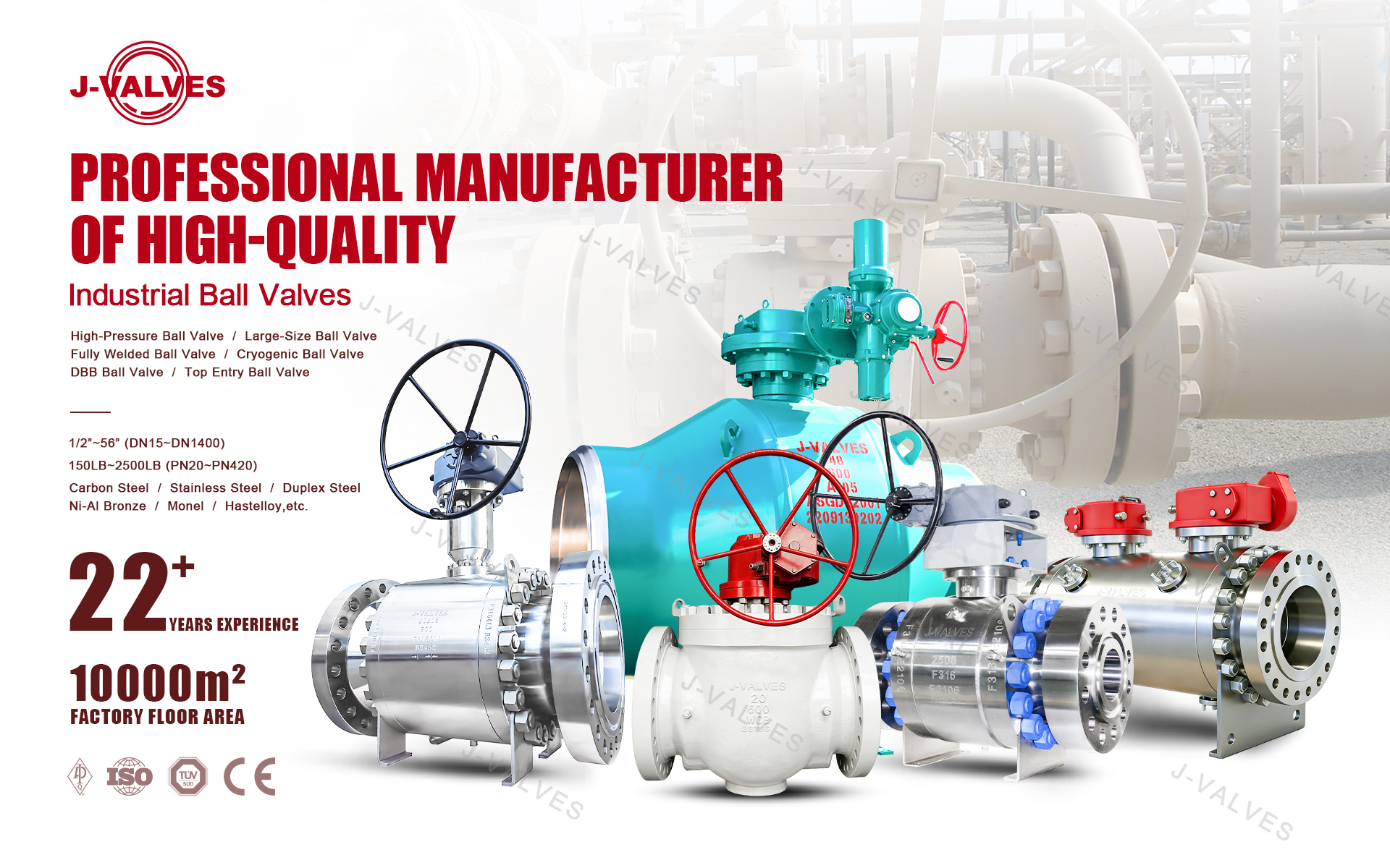
J-VALVES, a distinguished professional ball valve manufacturer rooted in China, takes pride in its extensive product portfolio. Our offerings span a wide range, including trunnion-mounted ball valves, floating ball valves, high-temperature ball valves, high-pressure ball valves, metal-sealed ball valves, ultra-low temperature ball valves, DBB ball valves, Three-way And Four-way Ball Valve, and fully welded ball valves. Each product is a testament to our commitment to precision engineering and reliable performance. Meticulously crafted, they are designed to not only meet but exceed the most stringent industrial demands, ensuring stable operation even under extreme conditions. This enables us to provide our clients with high-value services and makes our valves widely sought-after in industries.
Product Category
Contact Us


Pressure Class: ASME Class 150 / PN20, 19.6 bar at 38°C
Body Material: ASTM A351 CF8 (304), CF8M (316) optional
Ball: CF8, polished Ra 0.4 µm
Stem: SS316 or 17-4PH, blowout proof
Seat: PTFE, RPTFE, PPL, or Stellite faced metal
Packing: PTFE V-ring to 200°C, flexible graphite above
End Connection: Flanged RF to ASME B16.5
Face to Face: 127 mm, ASME B16.10 short pattern
Actuator Mounting: ISO 5211 F04 / F05
Air Supply: 0.4 to 0.7 MPa clean dry air
Design Standard: API 608, ASME B16.34
Test Standard: API 598, ISO 5208 rate A
Operation: Double acting or spring return pneumatic, manual override
-
Q641F
-
J-VALVES
A 1 inch pneumatic floating ball valve in Class 150 is a quarter-turn isolation valve with a DN25 bore, a ball that is free to move between two seat rings, ASME B16.5 raised-face flanged ends, and a pneumatic actuator mounted on an ISO 5211 pad. In a CF8 body the Class 150 rating is 19.6 bar at 38°C, line pressure pushes the ball into the downstream seat to make the seal, and the actuator only has to overcome friction and seat squeeze. That is why the body stays compact, the stem stays at 12 mm, and a small double-acting cylinder has torque to spare. It is the default answer for on-off isolation between 1/2 and 2 inch on water, air, steam and chemical lines that have to be operated by a signal rather than by hand.
J-VALVES manufactures this valve in CF8 and CF8M bodies with PTFE, RPTFE, PPL or Stellite-faced metal seats, and supplies it with double-acting or spring-return actuators, solenoid valves, limit switches, positioners, filter regulators and IP67 or IP68 protection. This page sets out the seat-load arithmetic that makes a floating ball correct at this size, the torque figures an actuator must be sized against, the temperature ladder behind the advertised -29°C to +425°C range, the flange and face-to-face dimensions, and the accessory set that turns a valve into a control element.

Why a Floating Ball Is Correct at 1 Inch and Wrong at 8 Inch
The choice between a floating and a trunnion mounted ball valve is not a preference, it is arithmetic. The force that seals a floating ball valve comes from line pressure acting on the projected area of the closed bore. The ball is pushed downstream into the seat ring, the seat ring is trapped in the body, and the contact stress between ball and seat does the sealing. The same force reaches the stem as a bending load, because the stem has to hold the ball against that push.
At 1 inch the bore is 25.4 mm, the projected area is 507 mm², and at the Class 150 rating of 1.96 MPa the thrust is 993 N, about one kilonewton. Over a stem length of roughly 60 mm that is a bending moment small enough for a 12 mm stem in 316 stainless to carry with a wide margin, and small enough that the seat does not need a spring to follow the ball. The design is simple, the torque is low, and there is nothing in it that can corrode out of adjustment.
At 8 inch the bore is 203 mm and the area is 32,429 mm². The same 1.96 MPa now gives 63.6 kN. No practical stem carries that as a bending load without deflecting enough to score the packing, and no polymer seat survives the resulting unit pressure. So the ball is held fixed on trunnions at top and bottom, the trunnions pass the thrust into bearings in the body, and the seat becomes a spring-loaded ring that floats towards the ball instead. That is the whole reason the industry splits at about 6 inch, and it is why a page selling a 1 inch valve has no business describing trunnion bearings.
Size | Bore | Projected area | Thrust at Class 150 | Normal construction |
|---|---|---|---|---|
1 inch | 25.4 mm | 507 mm² | 1.0 kN | Floating |
2 inch | 50.8 mm | 2,027 mm² | 4.0 kN | Floating |
3 inch | 76.2 mm | 4,560 mm² | 8.9 kN | Floating |
4 inch | 101.6 mm | 8,107 mm² | 15.9 kN | Floating |
6 inch | 152.4 mm | 18,246 mm² | 35.8 kN | Floating or trunnion |
8 inch | 203.2 mm | 32,429 mm² | 63.6 kN | Trunnion |
12 inch | 304.8 mm | 72,966 mm² | 143 kN | Trunnion |
Two practical consequences follow. First, a floating ball valve seals in both directions without a preferred flow arrow, because whichever side is pressurised pushes the ball into the opposite seat. Second, when the valve is closed and the trapped cavity heats up, the seat lifts off the ball and relieves the cavity into the line, so a floating valve does not normally need an external relief device at this size.
The Temperature Range, and the Seat That Actually Sets It
The catalogue line reads -29°C to +425°C, and that figure belongs to the metal parts, not to the valve as supplied. Body, ball and stem in CF8 hold their strength across the whole band. The seat is a polymer, and it sets the real limit. A buyer who orders a PTFE seat for a 300°C steam line has ordered a valve that will extrude its seat on the first heat-up and leak on the second.
Seat material | Service range | Behaviour that decides the choice |
|---|---|---|
Virgin PTFE | -29°C to +180°C | Best chemical resistance and lowest torque, but cold-flows under load above about 120°C and takes a permanent set |
RPTFE, 15% glass or carbon filled | -29°C to +200°C | Stiffer, less creep, about 20% higher torque; the standard seat for general chemical service |
PPL, polyphenylene | -29°C to +260°C | Holds shape under steam and hot oil; harder, so breakaway torque rises and the actuator must be sized for it |
PEEK | -60°C to +260°C | Highest strength of the polymers, used where cycling under load is frequent; abrasive to a soft ball coating |
Metal, Stellite faced | -29°C to +425°C | For steam above 260°C, abrasive slurries and fire survival. Not bubble tight; leak rate must be agreed to ISO 5208 |
CF8 is ASTM A351 grade 304 with 18% chromium and 8% nickel. It is the right body for water, steam, air, most organic acids, food contact and general chemical service, and it is cheaper than CF8M at every size. The boundary is chloride. Above roughly 200 ppm chloride with the fluid above 60°C, 304 begins to pit and to suffer crevice corrosion under gaskets and in the seat pocket. In that duty the body moves to CF8M, which is 316 with 2 to 3% molybdenum, and the price difference at 1 inch is small against the cost of a leaking isolation valve on a brine line.
Packing follows the seat. PTFE V-ring packing is standard up to 200°C at the gland. Above that, and for any steam service, the packing becomes flexible graphite, because PTFE at 250°C will extrude past the gland follower and the loss is not recoverable by tightening.
Torque, and Why the Actuator Is Deliberately Oversized
Actuator selection starts from a number, not from a size chart. For a 1 inch Class 150 floating ball valve the break-to-open torque at full differential pressure is typically 12 to 18 N·m when the valve is new, clean and at ambient temperature. Running torque is roughly half that. Both figures rise in service, and they rise predictably.
Condition | Break-to-open torque | What causes the increase |
|---|---|---|
New valve, ambient, dry | 12–18 N·m | Baseline seat squeeze and packing friction |
After 10 thermal cycles to 180°C | 20–30 N·m | Seat takes compression set, ball and seat pocket grow at different rates |
PPL seat at 260°C | 30–40 N·m | Harder seat material, reduced clearance, dried lubricant |
Process deposit on the ball | Add 50–100% | Scale, polymer or crystallised product bridging ball to seat |
Spring-return cylinder at 0.4 MPa minimum air | Multiply by 1.4 | The spring has to be compressed by the same air that produces the output torque |
A double-acting actuator is therefore sized at 1.3 to 1.5 times the worst-case break-to-open torque evaluated at minimum air pressure, not at nominal 0.6 MPa. A spring-return actuator is sized so that the spring alone can deliver the closing torque with the cylinder at minimum air and the seat at maximum temperature, which normally means one or two sizes larger than the double-acting unit on the same valve. Under-sizing does not produce a slow valve. It produces a valve that stalls part open and leaves the process in a state nobody can define.
Fail Safe, and What the Spring Actually Does
Spring return is usually specified as "fail closed", and that phrase is where most of the confusion sits. A spring-return actuator drives the valve to its spring position when air is lost. Whether that position closes or opens the process depends on how the valve was assembled, not on the spring. The same actuator body can be built air-to-open or air-to-close, and the two are not interchangeable in the field.
Three cases need separating. On loss of instrument air, a spring-return unit moves to the spring position and a double-acting unit stays where it is, which for a double-acting valve on a liquid line can be worse than either open or closed. On loss of electrical power, nothing moves unless the solenoid is normally closed and de-energises to exhaust, which is why the solenoid function and the actuator function have to be specified together. On loss of both, only the spring acts. A safety review that assumes "pneumatic valve equals fail safe" without checking those three cases is the most common error on small-bore isolation packages.
For a double-acting valve that must nevertheless close on air failure, the options are a spring-return actuator, an air receiver with a check valve sized for one full stroke, or an accumulator plus a solenoid that trips on low pressure. Each has a different cost and a different proof-test requirement, and the choice belongs in the datasheet rather than in the supplier's default.
Flanges, Face-to-Face and Installation
Dimension | 1 inch Class 150 to ASME B16.5 / B16.10 |
|---|---|
Flange outside diameter | 108 mm |
Bolt circle | 79.4 mm |
Bolting | 4 × 1/2 inch, ASME B18.2.1 |
Raised face height | 2 mm, RF finish 125 to 250 AARH |
Face-to-face, flanged short pattern | 127 mm |
Actuator mounting | ISO 5211 F04 or F05 pad, 9 or 11 mm star drive, confirm at order |
Preferred orientation | Stem vertical, actuator above the pipe |
Because the valve is bidirectional there is no flow arrow to respect, but orientation still matters for life. A stem pointing sideways puts the actuator weight as a bending load on the gland and shortens packing life. A stem pointing down collects condensate in the packing area on a cold line. Vertical up is the default and the only position that needs no justification.
Flange bolting is tightened in a cross pattern in three passes to the gasket manufacturer's torque, and the two flange faces must be parallel before tightening. Pulling a misaligned pipe into place with the valve bolts loads the body casting, and a cast CF8 body is far less tolerant of that than the steel pipe either side of it. On a 1 inch line the leverage available to a fitter is easily enough to crack a flange.

Testing, Certification and the Documents That Ship With the Valve
Every valve gets an API 598 shell test at 1.5 times the 38°C rating, which is 29.4 bar for Class 150, and a seat test at 1.1 times, which is 21.6 bar, with the leakage judged against ISO 5208 rate A for a soft-seated valve. The shell test is done with water and the seat test with air or nitrogen, and both results are recorded against the serial number.
The documentation set is the part buyers compare. J-VALVES issues an EN 10204 3.1 material certificate for body, ball and stem, a dimensional report for face-to-face and flange, the shell and seat test record, and a hydrostatic test certificate for the assembly. API 607 fire testing is available as an option on the same body, and ISO 15848-1 fugitive emission testing is available where the site has an LDAR programme. Actuator and solenoid documentation is supplied separately by the accessory manufacturer, including the ATEX certificate where the solenoid is installed in Zone 1 or Zone 2.

Where This Valve Earns Its Place
Application | Configuration that works | Reason |
|---|---|---|
Water treatment and RO skids | CF8, PTFE seat, double acting | Clean fluid, frequent cycling, lowest torque and cost |
Steam tracing and condensate | CF8, PPL seat, graphite packing, spring return closed | 180 to 220°C saturated steam destroys a PTFE seat; spring closes on air loss |
Chemical dosing and injection | CF8M, PTFE seat, positioner | Chloride and acid duty needs molybdenum; throttling needs a positioner |
Compressed and instrument air | CF8, PTFE, double acting, 24 V DC solenoid | Dry clean gas, high cycle count, low torque |
Food, beverage and CIP | CF8, PTFE, full bore, sanitary finish on request | Internal surface finish and drainability decide cleanability |
Tank farm and utility headers | CF8, RPTFE, spring return, limit switches | Remote indication of open or closed at the control room |
What to Put on the Enquiry
A quotation that comes back wrong is almost always a quotation that was asked for vaguely. The list that closes a 1 inch pneumatic floating ball valve in one exchange is: size and pressure class, body material, seat material, design temperature, fluid with concentration, end connection and face-to-face dimension, actuator type with fail action, minimum and normal air supply pressure, solenoid voltage and function, limit switch type, ingress protection, hazardous area classification, test standard and certification, marking and nameplate language, and quantity with required delivery.
Standard lead time is 3 to 5 weeks for CF8 with a PTFE seat and an aluminium actuator, and 6 to 8 weeks where the body is CF8M, the seat is PPL and the actuator carries a positioner and ATEX certification. Drawings are issued for approval before machining whenever the face-to-face dimension or the stem drive differs from the standard.
Pneumatic Floating Ball Valve FAQ
What is the difference between a floating ball valve and a trunnion ball valve?
In a floating ball valve the ball is held only by the two seat rings and moves downstream under line pressure, so the pressure itself creates the seal. In a trunnion ball valve the ball is fixed on bearings at top and bottom and the seats are spring loaded towards it. Floating is used up to about 6 inch and Class 300 because the thrust stays manageable; trunnion takes over above that, where the thrust at 8 inch Class 150 already reaches 63 kN.
What pressure does a 1 inch Class 150 ball valve hold?
19.6 bar at 38°C for a CF8 or CF8M body under ASME B16.34 group 2.2, which corresponds to PN20. The rating falls with temperature, and the seat material usually becomes the limiting item before the body does: a PTFE seat is practical to about 180°C and a PPL seat to about 260°C.
Should I choose double acting or spring return?
Double acting if the valve may stay in its last position on air failure and the process can tolerate it, because it is smaller, cheaper and uses less air. Spring return if the valve must move to a defined position when air is lost, which is the normal requirement for safety shut-off, steam isolation and any duty where a part-open valve is a hazard.
How much air does the actuator need?
A 1 inch Class 150 floating ball valve needs a cylinder in the 32 to 50 mm bore range for double acting service, consuming roughly 0.15 to 0.4 litre per stroke at 0.5 MPa. Supply pressure should be 0.4 to 0.7 MPa clean dry air, and the torque must be checked at 0.4 MPa rather than at the nominal figure, because that is the pressure the actuator will see when the compressor is struggling.
Can this valve be used for steam?
Yes, with the seat and packing changed. Saturated steam at 180°C needs a PPL seat and graphite packing; PTFE will extrude. Above 260°C the seat becomes metal, Stellite faced, and the leak rate has to be agreed to ISO 5208 because a metal seat is not bubble tight. The body stays CF8, since 425°C is within its rating.
Is a pneumatic ball valve fail safe?
Only if it is spring return and only for the failure mode the spring covers. A spring-return unit moves to its spring position on loss of air. A double-acting unit stays where it is. On loss of electrical power nothing moves unless the solenoid is normally closed. The three cases have to be checked separately against the process safety requirement.
Hot Products


News
Ball Valves in A Kraft Pulp Mill: Black Liquor, Green Liquor And The Cost of Choosing The Alloy by Habit
White liquor at pH 14 cracks carbon steel welds, black liquor sets solid below 100 C, green liquor dregs grind seats: alloy choice and torque in a kraft mill.
Read More
Slug Flow And Ball Valves: What Actually Arrives At The Seat
A slug is liquid mass with momentum, not a pressure spike. What changes at the seat, in the cavity and at the actuator when liquid reaches a ball valve.
Read More
Ball Valves in Direct Lithium Extraction: PH 1 Eluate, Gypsum Scale And 438,000 Cycles in Twenty-Five Years
Direct lithium extraction swings valves from pH 1 eluate to pH 12 caustic, 48 column switches a day and gypsum scale. Materials, seats and torque.
Read More
Ball Valves in Geothermal Brine: Silica Scale, Chloride Cracking And The Cooling Trap
Why geothermal brine destroys ball valves: retrograde silica scale, calcite at the flash point, chloride cracking above 60 C and the 250 C seat limit.
Read More