


CHINA J-VALVES Offers Various High-quality I ndustrial Ball Valves
J-VALVES, a distinguished professional ball valve manufacturer rooted in China, takes pride in its extensive product portfolio. Our offerings span a wide range, including trunnion-mounted ball valves, floating ball valves, high-temperature ball valves, high-pressure ball valves, metal-sealed ball valves, ultra-low temperature ball valves, DBB ball valves, Three-way And Four-way Ball Valve, and fully welded ball valves. Each product is a testament to our commitment to precision engineering and reliable performance. Meticulously crafted, they are designed to not only meet but exceed the most stringent industrial demands, ensuring stable operation even under extreme conditions. This enables us to provide our clients with high-value services and makes our valves widely sought-after in industries.
Product Category
Contact Us

Pressure Class: ASME Class 150, 300, 600, 900, 1500
Valve Type: Floating or trunnion mounted ball valve
Actuator Type: Rack and pinion or scotch yoke, double acting or spring return
Air Supply: 2 to 8 bar, sized at the plant minimum typically 4.5 bar
Safety Factor: 1.5 times the maximum break-to-open torque
Fail Position: Fail closed, fail open, or fail last with lock-up valve
Mounting: ISO 5211 flange and star drive
Accessories: Solenoid 5/2 or 3/2, limit switch, filter regulator, quick exhaust, positioner
Body Material: WCB, CF8M, CF8, A105, F316
Seat: PTFE, RPTFE, PEEK, metal seated
Stroke Time: 0.5 to 3 seconds typical
Design Standard: API 6D, API 608, ASME B16.34
-
Q641F
-
J-VALVES

A pneumatic ball valve is a quarter-turn ball valve fitted with an air powered actuator, so the valve opens or closes on a pneumatic signal instead of a hand lever. The valve itself is ordinary; what makes the assembly work or fail is the actuator sizing, the air supply and the answer to one question that must be settled before anything is ordered: when the air or the power fails, should this valve open, close, or stay where it is?
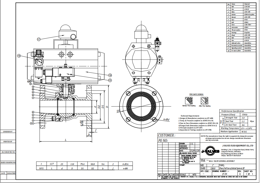
J-VALVES supplies pneumatic ball valves from 1/2 to 24 inch, in floating and trunnion designs, with double acting and spring return actuators, matched torque, ISO 5211 mounting, and the usual accessories: solenoid valve, limit switch box, air filter regulator, quick exhaust and lock-up valve. They are used on water, gas, steam, chemical and slurry lines where fast, remote or frequent operation is needed. This page covers actuator selection, the accessories that make the assembly complete, and the failure modes that show up in commissioning.
Double Acting or Spring Return
This is the first decision, and it is a safety decision rather than a technical one. Everything else follows from it.
Property | Double acting | Spring return (single acting) |
|---|---|---|
How it moves | Air opens, air closes | Air drives one way, springs drive the other |
On air failure | Stays in the last position | Returns to the spring position: fail closed or fail open |
Actuator size | Smaller, because both strokes are powered | Larger, because the springs must be overcome in one direction |
Air consumption | One cylinder volume per stroke | Same, but the spring side vents to atmosphere each stroke |
Cost | Lower | Higher at the same torque |
Use when | The valve can stay put on failure, or the process has its own interlock | Isolation must close on failure, or a vent path must open on failure |
Fail closed is the usual choice for isolation and for anything feeding a burner, a reactor or a loading arm. Fail open is used for vents, relief paths and cooling water where stopping flow is the hazard. Fail last is right for changeover valves and for lines where an unplanned movement is worse than an unplanned position, which is why duplex filter valves are often double acting with a lock-up valve.
Sizing the Actuator
Actuator sizing is arithmetic, and it is done wrong more often than any other part of the assembly. The valve's torque is not one number: it is a set of numbers that depend on pressure, temperature, medium and seat material, and the actuator must beat the worst of them.
Step | What to establish | Typical value |
|---|---|---|
1 | Maximum break-to-open torque of the valve at the worst condition | From the valve data or a bench measurement |
2 | Temperature multiplier | 1.3-1.6 above 200°C, more with metal seats |
3 | Medium multiplier | 1.1-1.3 for dry gas or slurry |
4 | Safety factor | 1.5 for pneumatic, applied to the maximum |
5 | Air supply at its minimum, not nominal | Often 4.5 bar where the plant claims 6 bar |
6 | Select actuator output torque at that minimum pressure | Output must exceed step 4 |
A worked example: a 6 inch Class 300 trunnion valve with a measured break-to-open torque of 420 N·m at ambient. At 180°C the multiplier is 1.4, giving 588 N·m; the safety factor of 1.5 gives 882 N·m. The actuator must therefore produce at least 882 N·m at 4.5 bar, not at 6 bar. An actuator rated 900 N·m at 6 bar will produce about 675 N·m at 4.5 bar and will stall.
Spring return actuators have a second number: the spring torque at the end of the stroke. The springs must still close the valve against the process, so the spring torque must exceed the valve's break-to-close torque at the worst condition, not the running torque. Catalogues list both air torque and spring torque for exactly this reason.
The Accessories That Make It Complete
An actuator alone is a device that can be told to move. The accessories are what turn it into a control element, and leaving one out is the most common cause of a commissioning delay.
Accessory | Function | Choose it when |
|---|---|---|
Solenoid valve, 5/2 | Directs air to both sides of a double acting actuator | Double acting, remote operation |
Solenoid valve, 3/2 | Supplies and exhausts one side of a spring return actuator | Spring return, fail safe |
Limit switch box | Confirms open and closed position to the control system | Always, if the DCS needs feedback |
Air filter regulator | Sets and holds the supply pressure, removes water and dirt | Always; unfiltered air is the main cause of actuator failure |
Quick exhaust | Vents the cylinder locally for a faster stroke | Fast closing required, or long air lines |
Lock-up valve | Holds the last position on air loss | Fail last required with a double acting actuator |
Positioner | Positions the ball proportionally to a signal | Modulating duty, not on-off |
Manual override | Handwheel or declutchable gear | Always worth specifying for critical isolation |
Two notes from the field. First, a solenoid valve is an electrical device: on a hazardous area installation the coil, the enclosure and the cable entry all carry a certification, and a general purpose solenoid on a Zone 1 skid is a finding at inspection. Second, the air supply quality matters more than the pressure: water and oil in the air destroy the actuator seals and the solenoid in months, and a filter regulator with a drain that nobody empties is not filtration.
Mounting, Interface and Stroke
Actuators and valves are joined through an ISO 5211 mounting flange and a female star or double-D drive. The standard defines flange size, bolt circle, bolt size and drive dimensions by torque range, which is why an actuator from one supplier can be fitted to a valve from another if both follow it.
Three details decide whether the assembly works. The drive engagement must be deep enough that the actuator cannot lift off under torque; the spool adaptor must match the valve stem exactly, because a loose fit becomes backlash and then a broken stem key; and the stroke stops must be set on the valve, not used to force the ball past its seat. On a spring return unit, the mechanical travel stop in the closing direction is set with the air off, because that is the position the springs will drive to.

Where Pneumatic Beats Electric
Pneumatic actuation wins on speed, on cost at large torque, and on safety in hazardous areas, and it loses wherever there is no reliable instrument air.
Factor | Pneumatic | Electric |
|---|---|---|
Stroke time | 0.5-3 seconds typical | 10-60 seconds typical |
Cost at high torque | Lower above about 1,000 N·m | Higher, gear motor and controls |
Fail safe | Spring return, no power needed | Battery or capacitor backup, or spring return motor |
Hazardous area | Simple, only the solenoid is electrical | Requires Ex rated motor and enclosure |
Modulating duty | Possible with a positioner, air hungry | Natural fit, 4-20 mA and feedback |
Dependency | Instrument air must be dry and available | Power must be available; no air needed |

Commissioning and Troubleshooting
Most pneumatic ball valve problems show up in the first week, and almost all of them fall into six patterns. Working from the symptom backwards is faster than re-reading the datasheet.
Symptom | Most likely cause | Check |
|---|---|---|
Valve does not move at all | No air, solenoid not energised, or actuator in manual | Pressure at the actuator port, solenoid coil voltage, override position |
Moves part way and stalls | Actuator undersized, or air supply below the sizing pressure | Supply pressure at the actuator under flow, not at the header |
Moves slowly | Blocked exhaust, undersized tubing, or clogged filter | Exhaust silencer, tube bore, filter element |
Will not hold closed position | Ball not travelling to the seat, or stroke stop set wrong | Closed stop setting with air applied, and the ball position at the seat |
Spring return does not return | Spring torque below the valve break-to-close torque, or a stuck spool | Spring torque figure against measured break-to-close, solenoid exhaust path |
Position feedback wrong | Limit switch cams set to the actuator stroke rather than the valve stroke | Set cams on the valve, then confirm the signal at the DCS |
Three habits prevent most of the list. Blow the air line through before connecting the actuator, because the debris in a new instrument air line is what destroys the first set of seals. Set the stroke stops against the valve, with the air on, and then confirm by hand that the ball is on the seat. And record the actual stroke time and supply pressure at commissioning; when the valve slows down a year later, that record is the only baseline anyone will have.

Pneumatic Ball Valve FAQ
What is the difference between double acting and spring return pneumatic ball valves?
A double acting actuator uses air to open and air to close, so on air failure the valve stays where it is. A spring return actuator uses air in one direction and springs in the other, so on air failure the valve goes to its spring position, normally closed or open. Spring return needs a larger actuator for the same valve torque and costs more.
How do I size a pneumatic actuator for a ball valve?
Take the valve's maximum break-to-open torque at the worst condition, apply the temperature and medium multipliers, multiply by 1.5, then select an actuator whose output at the minimum air supply pressure exceeds that figure. For spring return, also check that the spring torque exceeds the valve's break-to-close torque.
What air pressure does a pneumatic ball valve need?
Most rack and pinion actuators are rated for 2 to 8 bar and are sized at 5.5 bar nominal. The critical number is the minimum pressure the plant can actually guarantee, often 4 to 4.5 bar, and the actuator must be selected at that pressure, not at the nominal figure.
What happens to a pneumatic ball valve when the air fails?
With a spring return actuator it moves to the spring position, which is set at order as fail closed or fail open. With a double acting actuator it stays in the last position, unless a lock-up valve is fitted to hold it deliberately. If the requirement is "must not move", specify double acting plus lock-up rather than spring return.
Can a pneumatic ball valve be used for modulating control?
Yes, with a positioner instead of a solenoid valve, but it is an air-hungry solution. Pneumatic actuators are best at on-off duty; for continuous modulating service an electric actuator with 4-20 mA control is usually the better fit, and for fast modulating duty a pneumatic positioner with a volume booster is used.
What do you need to quote a pneumatic ball valve?
Valve size, class, body and seat material, design pressure and temperature, fluid, required break torque if known, double acting or spring return, fail position, air supply pressure available, solenoid voltage and hazardous area classification, limit switch requirement, accessories, and quantity.
Hot Products


News
Ball Valves in A Kraft Pulp Mill: Black Liquor, Green Liquor And The Cost of Choosing The Alloy by Habit
White liquor at pH 14 cracks carbon steel welds, black liquor sets solid below 100 C, green liquor dregs grind seats: alloy choice and torque in a kraft mill.
Read More
Slug Flow And Ball Valves: What Actually Arrives At The Seat
A slug is liquid mass with momentum, not a pressure spike. What changes at the seat, in the cavity and at the actuator when liquid reaches a ball valve.
Read More
Ball Valves in Direct Lithium Extraction: PH 1 Eluate, Gypsum Scale And 438,000 Cycles in Twenty-Five Years
Direct lithium extraction swings valves from pH 1 eluate to pH 12 caustic, 48 column switches a day and gypsum scale. Materials, seats and torque.
Read More
Ball Valves in Geothermal Brine: Silica Scale, Chloride Cracking And The Cooling Trap
Why geothermal brine destroys ball valves: retrograde silica scale, calcite at the flash point, chloride cracking above 60 C and the 250 C seat limit.
Read More