


CHINA J-VALVES Offers Various High-quality I ndustrial Ball Valves
J-VALVES, a distinguished professional ball valve manufacturer rooted in China, takes pride in its extensive product portfolio. Our offerings span a wide range, including trunnion-mounted ball valves, floating ball valves, high-temperature ball valves, high-pressure ball valves, metal-sealed ball valves, ultra-low temperature ball valves, DBB ball valves, Three-way And Four-way Ball Valve, and fully welded ball valves. Each product is a testament to our commitment to precision engineering and reliable performance. Meticulously crafted, they are designed to not only meet but exceed the most stringent industrial demands, ensuring stable operation even under extreme conditions. This enables us to provide our clients with high-value services and makes our valves widely sought-after in industries.
Product Category
Contact Us


-
J-VALVES-Q41F
-
J-VALVES
Overview of the J-VALVES DN80x50 1500LB F44 Two Piece Extended Stem Floating Ball Valve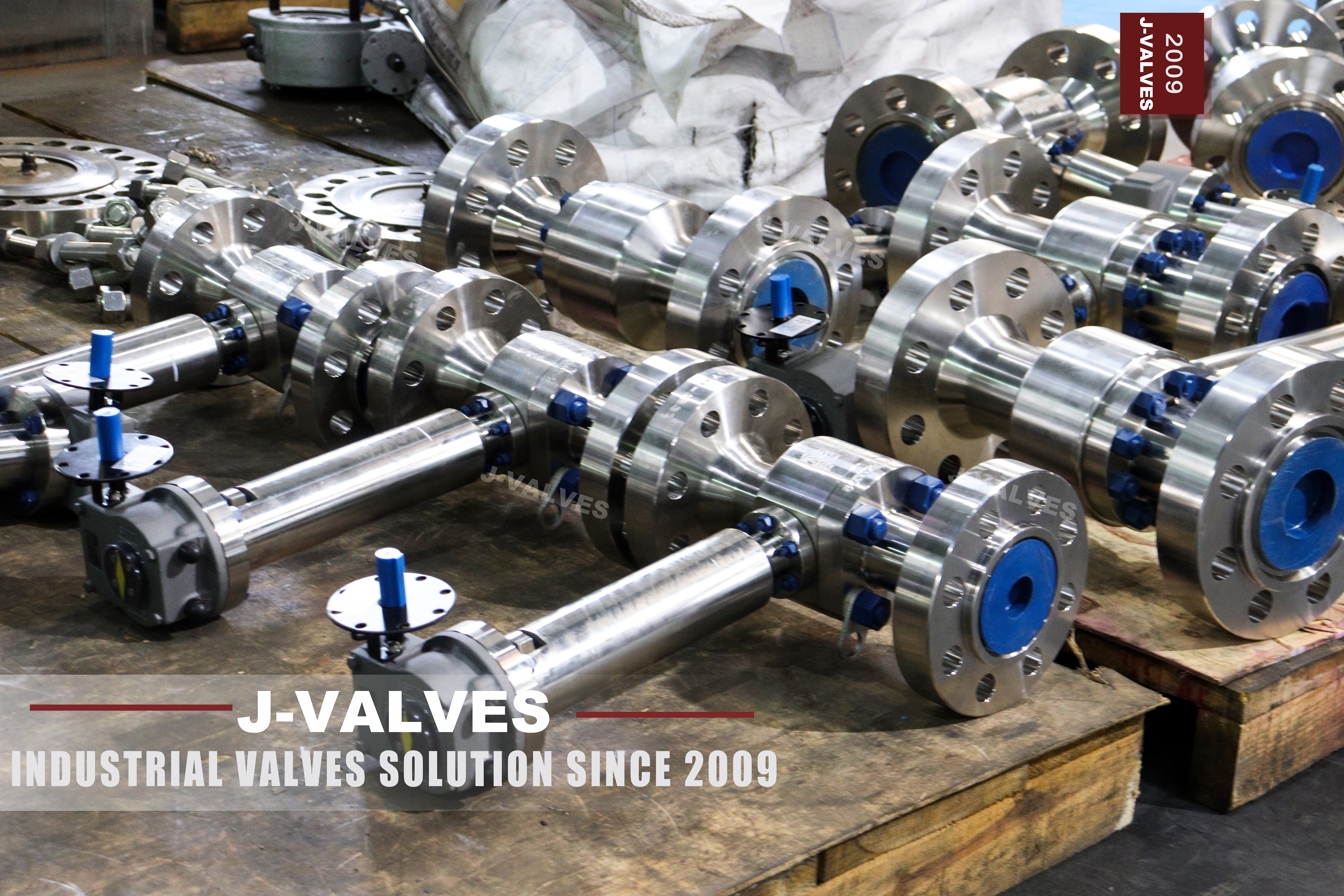
Two sizes appear on this valve and they do different jobs. The DN80 is the flange, so it is the pipe it bolts to and the pattern that sets the face to face and the bolt circle. The DN50 is the bore, so it is what the medium passes through and what the ball and the seats are sized by. A three inch line gets a valve that fits it and passes what a two inch line would pass, and that is a deliberate choice rather than a restriction.
The choice is what keeps the design simple. Seat load in a floating valve follows the bore area and the pressure, not the flange size. At Class 1500 with a two inch bore that load stays inside what a polymer or a metal seat can take, so the ball can float and no trunnion is needed. A full bore three inch valve at the same rating would be a much heavier proposition, and it is normally trunnion mounted for exactly that reason.
Design and Construction
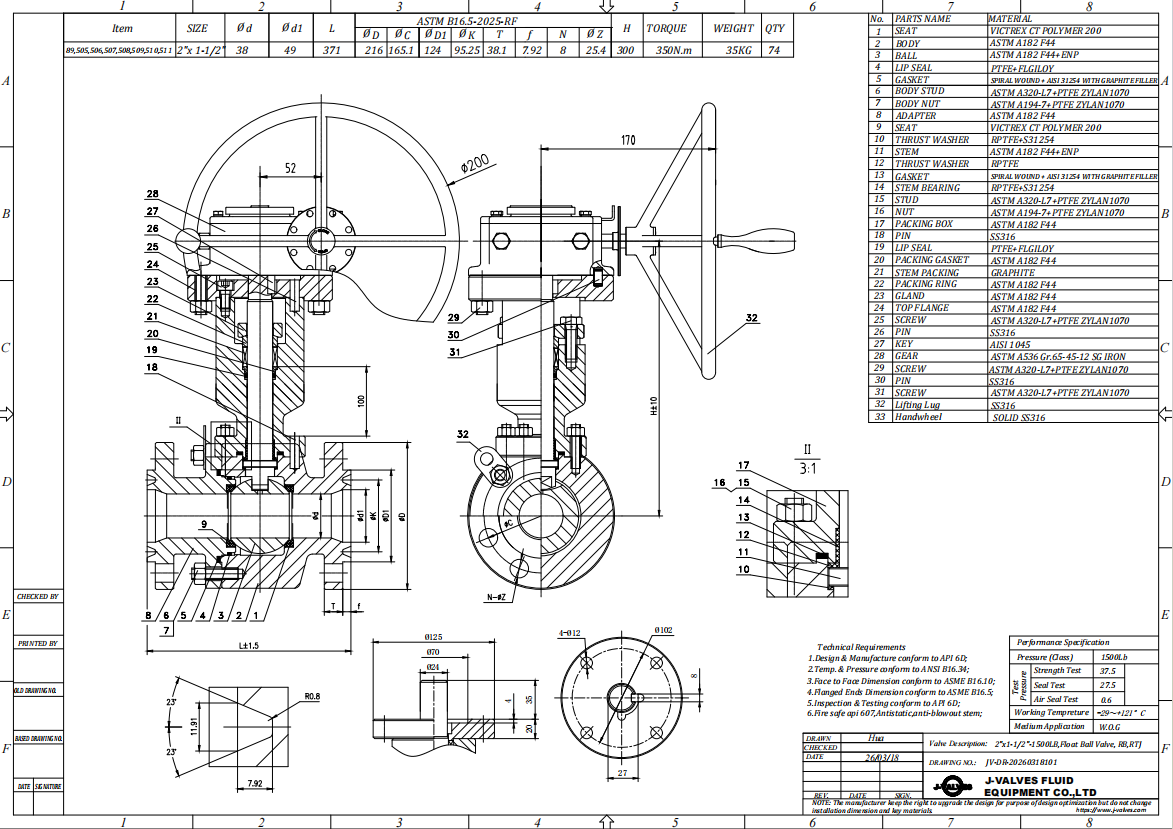
Two pieces, one bolted joint, a floating ball, ring joint ends and an extended stem. The body splits at the joint, the internals go in from that side, and the joint is the only pressure boundary that is not a weld or a flange. At Class 1500 that joint is the part of the design that needs the most care, because the studs have to hold a high pressure across a large gasket face while the two halves stay parallel.
The extended stem is a separate assembly from the pressure boundary. It carries the lever up through insulation or through a pit cover and couples to the stem that passes through the packing, which stays in the body where the pressure is. Nothing about the extension is rated; it is a mechanical part that has to transmit torque without play and without side load on the gland. Its length is set by the installation, not by the valve.
Material Options
F44 is a super austenitic stainless grade with a high molybdenum content, and it is bought for one property: resistance to chloride attack. In a medium where a standard austenitic grade would pit or crack, the higher alloy content keeps the passive film intact, which is why this valve turns up on seawater, brine and chloride bearing process lines. The grade is a catalogue code; the composition and the heat treatment behind it belong on the mill certificate, not on the product page.
That distinction matters at the order stage. The page names a forged grade and lists its alternatives, and a buyer is entitled to know which alloy family he is getting, but the specific grade and its heat treatment are certified per heat. Writing the code on the order and letting the 3.1 certificate carry the chemistry is the reliable route; converting the code into a standard designation on the strength of a catalogue line is not, and it is how grade errors get into purchase orders.
| Component | Standard Material | Optional Upgrade | Service Notes |
|---|---|---|---|
| Body and end pieces | forged F44 super austenitic stainless | as the certificate states | two pieces, one bolted joint |
| Ball | F44 with hard chrome or nitriding | as the seat arrangement requires | hardness difference needed for a metal seat |
| Stem | F44 or precipitation hardening stainless | as the order states | packing stays in the body |
| Seat | reinforced PTFE, PEEK or PPL | metal seat, leakage rate to the order | carries the full differential |
| Packing | high density flexible graphite | as the order states | gland adjustable |
| Extension | F44, 300 mm to 1500 mm typical | length to the drawing | not a pressure boundary |
| Bolting | high strength alloy steel named on the order | coating to the environment | not the body alloy at this class |
Technical Specifications
The size sheet gives two sets of numbers and they should not be mixed. The flange dimensions, the face to face and the bolt circle all follow the DN80 pattern at Class 1500, because that is the size that meets the pipe. The bore, the ball diameter and the seat size follow DN50. When a quotation is compared, the first question is which of the two numbers it was built around, because a price quoted on the bore is not a price for the flange.
Class 1500 is written as PN 250 in the pressure class notation used for pipeline valves, not as PN 260. The difference is not cosmetic: 250 is a listed designation and 260 is not, and a certificate that carries a designation nobody can look up is a certificate that will be queried at goods receipt. The end facing at this class is ring joint, which is a different product from a raised face valve of the same size and cannot be converted at site.
| Item | Value |
|---|---|
| Nominal size | DN80 x DN50 (three inch flange, two inch bore) |
| Pressure class | Class 1500, written as PN 250 |
| Body construction | two piece, forged, one bolted joint |
| Ball support | floating, no trunnion |
| Bore | reduced bore, DN50 |
| Body material | forged F44 super austenitic stainless, grade as stamped |
| Ball material | F44 with hard chrome or nitriding |
| Stem | F44 or precipitation hardening stainless |
| Seat | reinforced PTFE, PEEK or PPL; metal seat optional |
| Packing | high density flexible graphite |
| Extended stem length | 300 mm to 1500 mm typical, set by the installation |
| End connection | ring joint to ASME B16.5, Class 1500 |
| Face to face | to the DN80 pattern, dimension on the signed GA drawing |
| Design standard | ASME B16.34 and API 608 |
| Test standard | API 598 shell and seat test |
| Test pressure | shell 1.5 times and seat 1.1 times the class rating |
| Bolting | high strength alloy steel, grade named on the order |
| Temperature range | minus 29 to plus 425 Celsius, metal temperature, seat limited |
| Pressure class notation | PN 250, not PN 260 |
| Operation | lever, worm gear, pneumatic, electric or hydraulic |
| Marking | size, class, body code, heat number |
| Documentation | EN 10204 3.1 on request |
| Weight | quoted with the drawing for the size and trim ordered |
| Country of manufacture | China |
Standards and Compliance
ASME B16.34 sets the wall thickness and the pressure temperature rating at this class, and at Class 1500 both are substantial. API 608 covers the quarter turn requirements for a ball valve of this type. API 598 is the test standard, and its multipliers do not change with the class: one and a half times the rating for the shell and one and one tenth for the seat, which at this rating are high test pressures and a reason to check the test bench before the valve is on it.
Ring joint ends bring their own standard. The groove is cut into the flange face and the ring gasket sits in it, so the facing is part of the flange rather than something that can be changed later. The ring itself is a consumable and is replaced every time the joint is broken; reusing a ring that has been compressed once is the most common cause of a leak at a ring joint that was perfect when it was assembled.
| Requirement | Standard | What J-VALVES Supplies |
|---|---|---|
| Pressure boundary | ASME B16.34 | wall and rating table at Class 1500, written as PN 250 |
| Ball valve design | API 608 | quarter turn requirements |
| Shell and seat test | API 598 | 1.5 times the rating for the shell, 1.1 times for the seat |
| End facing | ASME B16.5 ring joint | groove cut in the flange, ring replaced at every opening |
| Pressure class notation | PN 250 | the listed designation, not PN 260 |
| Marking | API 608 and the order | size, class, body code, heat number |
| Documentation | EN 10204 3.1 | chemistry and heat treatment against the stamped code |
Manufacturing Process
Forging a super austenitic grade is harder than forging carbon steel because the alloy work hardens quickly, so the blank has to be worked hot and in stages. The body and the two end pieces are then machined in one setup where possible, with the bore, the seat pockets and the ring joint groove all referenced to each other. The groove in particular has to be cut to the standard profile, because a ring that does not seat properly will leak no matter how well the rest of the valve is made.
The ball is machined, then plated or nitrided depending on the seat arrangement; a metal seated valve needs a hardness difference between ball and seat to avoid galling. Seats are turned and lapped. Assembly is dry and clean, the body joint is drawn down to a controlled torque, and the extension is fitted and aligned so the stem turns freely. Every unit is then cycled and tested before marking.

Quality Control and Testing
Shell and seat tests follow API 598. At Class 1500 the shell test is a demanding one and the body joint is included in it, which is the point: the joint is the part most likely to leak, and a test that passes the body but skips the joint proves only half of what matters. The seat test is run in both directions at one and one tenth times the rating, and a metal seated valve is accepted on the leakage rate the order specifies rather than on zero leakage.
Material verification is separate from pressure testing. Positive material identification on the finished body and on the ball confirms the alloy that arrived, and it is the check that catches a grade substitution before the valve goes into a chloride service. Where the order asks for it, an intergranular corrosion test on a sample from the same heat is added. A hydrostatic test proves the valve holds; none of these prove what it is made of, and both questions have to be asked.
| Step | What Is Checked | Standard or Acceptance |
|---|---|---|
| Forging | grade, heat number, mechanical properties | 3.1 certificate against the stamped code |
| Machining | seat pocket coaxiality, ring groove profile | checked against the standard profile |
| Ball | roundness, plating or nitriding depth | sampled before assembly |
| Assembly | body joint torque, extension alignment | controlled torque, stem turns without side load |
| Shell test | no leakage through body or joint | API 598 at 1.5 times the rating |
| Seat test | both directions, metal seat by leakage rate | API 598 at 1.1 times the rating |
| Material identification | body and ball alloy | positive material identification where ordered |

Applications and Industry Service
This valve is for lines that combine three conditions: a chloride bearing medium, a high pressure class, and an operator who has to stand somewhere other than next to the pipe. That combination turns up on offshore water injection, on produced water and brine lines, on seawater systems where the pressure is high enough to need Class 1500, and on insulated process lines where the lever has to be outside the lagging.
It is not the answer for a line where the flow has to be full bore, because the reduced bore is a deliberate restriction and a pig will not pass. It is also wrong where the medium is clean water at low pressure, where a standard austenitic grade would do the same job for less, and where the extension is being used to solve a problem that is really about where the valve was installed. The alloy and the extension are both expensive answers to specific questions.

Installation, Operation and Maintenance
Ring joint joints are made up dry and clean, with a new ring every time, and the studs brought down in a cross pattern in stages. The faces have to be parallel before the studs are loaded, because a ring joint has almost no tolerance for a cocked flange and will leak at the point where the gap is widest. Support the valve and the extension: at this class the body is heavy and the extension is a lever arm that will load the gland if it is unsupported.
Maintenance is seat replacement through the body joint, with both seats changed as a pair and the ball inspected for plating or hardness loss at the same time. The ring gaskets are replaced at every joint that is opened. Packing is adjusted at the gland and replaced when the gland runs out of travel. The extension coupling should be checked for play whenever the gland is serviced, because play there shows up as a stem that turns but does not move the ball.
How to Specify and Order
The order should carry the flange size and the bore as two separate numbers, the class written as 1500 or as PN 250 but not both, the body grade, the seat material including whether it is metal seated, the facing as ring joint, the extension length with its datum, and the standards. The bolting deserves its own line: at this class the studs are normally a high strength alloy steel rather than the body alloy, and the grade and the coating belong on the order.
Before shipment, check the nameplate, the certificate and the drawing against each other, with the two sizes treated separately. The drawing should show DN80 flanges and a DN50 bore, and both should appear on the nameplate description. Where the facing is ring joint, the ring size and profile should be on the packing list so that the correct gaskets arrive with the valve rather than being sourced locally from a description.
FAQ
Q: Why is this valve DN80x50 rather than full bore?
A: Because the line is three inch and the flow only needs two. A reduced bore valve keeps the smaller ball, the smaller seats and the lower torque of the two inch size while presenting three inch flanges that match the pipe. The trade is a restriction in the line and a pig that will not pass. On a line where neither matters, the reduced bore is the cheaper and lighter way to isolate a three inch pipe.
Q: Why is a floating ball used at Class 1500?
A: Because the bore is two inch. Seat load in a floating valve follows the bore area and the pressure, so a two inch ball at Class 1500 produces a manageable load, whereas a three inch full bore ball at the same rating would not. That is the connection between the two numbers in the name: the reduction is what allows the simpler design, and a full bore three inch valve at this class is normally trunnion mounted.
Q: Is this valve 1500LB or PN250?
A: They are the same rating written in two systems, and the listed designation in the pipeline pressure class notation is PN 250. PN 260 appears on some catalogue pages and does not correspond to a listed designation in either the ASME or the European flange standard, so it should not be used on a nameplate or a purchase order. The order should carry one designation, and the certificate should use the same one.
Q: What is the extended stem for?
A: To put the operator where a person can reach it. The extension lifts the lever above insulation, above a pit cover or clear of a cold box wall, while the packing stays in the body where the pressure is. It is a mechanical part, not a pressure boundary, and its length is set by the installation and must be written on the order with the datum it is measured from.
Q: What is F44?
A: A catalogue code for a super austenitic stainless grade with a high molybdenum content, chosen for chloride resistance. On a purchase order the code should be written as it will be stamped on the valve, with the grade and the heat treatment confirmed by the mill certificate behind the 3.1 documentation. Converting the code into a standard designation on the strength of a catalogue line is how grade errors get into orders.
Q: Can the seat be replaced without removing the valve?
A: No. The body joint has to come apart and the valve has to be out of the line, because the seats are retained inside the body on both sides of the ball. That is the difference between this and a three piece design, where the centre section comes out with the seats in it. On a line where seat changes are expected to be frequent, the three piece body is worth the extra joints.


Hot Products


News
Ball Valves in A Kraft Pulp Mill: Black Liquor, Green Liquor And The Cost of Choosing The Alloy by Habit
White liquor at pH 14 cracks carbon steel welds, black liquor sets solid below 100 C, green liquor dregs grind seats: alloy choice and torque in a kraft mill.
Read More
Slug Flow And Ball Valves: What Actually Arrives At The Seat
A slug is liquid mass with momentum, not a pressure spike. What changes at the seat, in the cavity and at the actuator when liquid reaches a ball valve.
Read More
Ball Valves in Direct Lithium Extraction: PH 1 Eluate, Gypsum Scale And 438,000 Cycles in Twenty-Five Years
Direct lithium extraction swings valves from pH 1 eluate to pH 12 caustic, 48 column switches a day and gypsum scale. Materials, seats and torque.
Read More
Ball Valves in Geothermal Brine: Silica Scale, Chloride Cracking And The Cooling Trap
Why geothermal brine destroys ball valves: retrograde silica scale, calcite at the flash point, chloride cracking above 60 C and the 250 C seat limit.
Read More