

CHINA J-VALVES Offers Various High-quality I ndustrial Ball Valves
J-VALVES, a distinguished professional ball valve manufacturer rooted in China, takes pride in its extensive product portfolio. Our offerings span a wide range, including trunnion-mounted ball valves, floating ball valves, high-temperature ball valves, high-pressure ball valves, metal-sealed ball valves, ultra-low temperature ball valves, DBB ball valves, Three-way And Four-way Ball Valve, and fully welded ball valves. Each product is a testament to our commitment to precision engineering and reliable performance. Meticulously crafted, they are designed to not only meet but exceed the most stringent industrial demands, ensuring stable operation even under extreme conditions. This enables us to provide our clients with high-value services and makes our valves widely sought-after in industries.
Product Category
Contact Us


-
J-VALVES-Q41F
-
J-VALVES
Overview of the J-VALVES JIS 150A 10K CF8 floating ball valve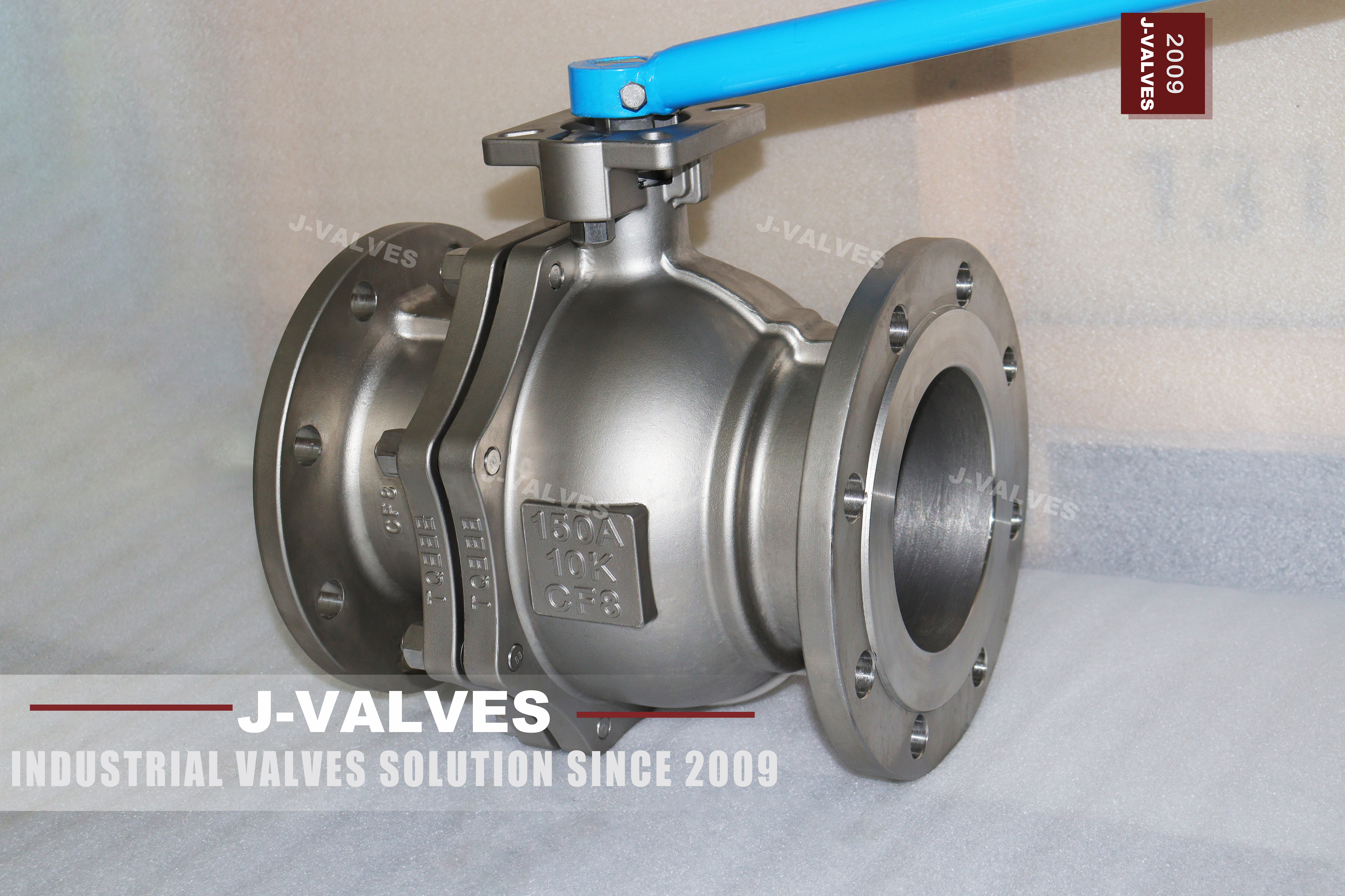
Two numbers on this page are not the same kind of number, and confusing them is the most common mistake made about JIS valves. 150A is a nominal bore size, roughly six inch in the imperial system. 10K is a pressure rating, one megapascal. A valve is 150A in size and 10K in rating, and neither of those figures can be read as the other, which is why the title of this page carries both.
The valve itself is a two piece cast stainless floating ball valve with flanges drilled to JIS B2220, built to JIS B2071 and tested to JIS B2003. That is a complete Japanese specification set, and it is what a buyer in Indonesia, Japan, Korea or a shipyard asks for when the piping class is written in the JIS system rather than the ASME one. It is the only page in this catalogue that works that way.
The point that matters commercially is the one that is usually left out: a JIS 10K flange and an ASME Class 150 flange are not interchangeable, even at the same nominal size. The bolt circle, the bolt count and the facing are different, so a 10K valve will not bolt into an ASME line and a Class 150 valve will not bolt into a JIS one. The two systems also rate the same nominal size differently, and the difference is larger than most buyers expect.
Design and Construction
Two castings make the body: a main body and a single end cap, held on one gasket face by a ring of studs. That single joint is the whole maintenance story. Take the cap off and the ball and both seats come out; leave it on and nothing inside is accessible. On a two piece body the joint is also a pressure boundary that sees full line pressure, so it cannot be opened until the line is isolated and the body is vented.
The ball floats between two seats and is pushed into the downstream seat by the pressure it is holding. At DN150 and 10K the force on the ball is modest, which is why a floating design is the right one at this size and this rating: the seat can carry the load, the torque stays low, and the lever is a lever rather than a gearbox.
The stem is a plain shaft with a shoulder under the gland, retained by the body so that pressure cannot blow it out. The lever has a locking hole so that the position can be pinned, and on a valve that is used as a block valve in a plant that is a small feature with a real purpose: a valve that drifts open on a header is a hazard nobody notices until something downstream is opened.
The flange facing is the detail that decides whether the joint works. JIS B2220 offers a flat face and a raised face, and the two are not interchangeable in a joint: a flat face flange mates with a flat face flange, and a raised face mates with a raised face. Mixing them is the second most common installation error on a JIS valve, after bolting it to an ASME flange and wondering why the holes do not line up.

Material Options
CF8 is the JIS cast stainless grade, equivalent to ASTM A351 CF8 and to 304 in wrought terms. It has no molybdenum, so it is the general purpose grade: water, steam condensate, most food and beverage service, and mildly aggressive chemicals. On a 10K valve that is usually enough, because the pressure is low and the medium is the only thing that decides the grade.
CF8M is the molybdenum bearing equivalent of 316 and is the option to take where there are chlorides, which in practice means seawater, brine, and the chemical and coastal services where 304 pits. CF3M is the low carbon version of CF8M, and its advantage is weldability rather than corrosion resistance: it is the grade to specify when the body will be welded, which on a flanged valve is not often.
| Component | Standard Material | Optional Upgrade | Service Notes |
|---|---|---|---|
| Body | JIS G5121 CF8 casting | CF8M for chlorides; CF3M for welded fabrication | Equivalent to ASTM A351 CF8 |
| Ball | CF8 or CF8M, integral | CF8 with hard chrome; electroless nickel plating | Lapped to its own seat |
| Stem | CF8 or CF8M | SUS304; SUS316; 2Cr13 for wear resistance | Blowout proof, shoulder under the gland |
| Seat | PTFE | Reinforced PTFE; PPL | The seat sets the working temperature |
| Packing | PTFE V rings | Flexible graphite | Graphite for the higher temperature end |
| Body joint gasket | Flexible graphite spiral wound | Rubber gasket for low temperature water service | One joint, one gasket |
| Bolting | SUS304 or SUS316 | Galvanised A193 B7 | Stainless bolting on a stainless body |
| Flange | JIS B2220 10K, flat face or raised face | — | Drilling is JIS, not ASME |
Technical Specifications
The table is short and the two numbers at the top are the reason the page exists. Everything below them is either a standard reference or a material choice, and none of it is a dimension that belongs to a drawing.
| Item | Value |
|---|---|
| Size | 150A, approximately DN150 or six inch |
| Pressure rating | 10K, one megapascal maximum working pressure, in the JIS system |
| Body style | Two piece cast body, floating ball, side entry |
| Body material | JIS G5121 CF8, equivalent to ASTM A351 CF8 |
| Body options | CF8M for chlorides; CF3M for welded fabrication |
| Ball | Integral CF8 or CF8M, lapped to its seat |
| Stem | CF8, CF8M, SUS304 or SUS316 |
| Seat | PTFE as standard; reinforced PTFE or PPL on request |
| Flange | JIS B2220 10K, flat face or raised face |
| Face to face | Confirmed on the signed GA drawing for the JIS size and rating |
| Temperature | Minus 29 to plus 425 C published for the body; the seat sets the working limit |
| Operator | Lever with a locking hole; worm gear, pneumatic or electric on request |
| Design standard | JIS B2071 |
| Test standard | JIS B2003 |
The temperature line needs the same reading as everywhere else in this catalogue. The body range is published as minus 29 to plus 425 C, and the seats offered are PTFE to 150 C, reinforced PTFE to 180 C and PPL to 280 C. A valve is a PTFE valve or a PPL valve; it is not a 425 C valve, and the number on the order should be the one the seat can hold.
Standards and Compliance
JIS B2071 is the design standard for this valve and JIS B2003 is the pressure test standard, and together they are the Japanese equivalent of the ASME plus API pair used elsewhere in the catalogue. A buyer who specifies JIS is not asking for a cheaper ASME valve; they are asking for a valve designed, tested and marked to a different document set, and the paperwork that comes with it is that set.
The rating comparison is where the two systems part company, and it is worth stating plainly because the source page gets it wrong. Ten K is one megapascal. Class 150 in ASME B16.34 is rated at 19.6 bar at 38 C for a carbon steel body and slightly less for an austenitic one, which is roughly twice the pressure. A 10K valve is therefore not equivalent to a Class 150 valve and must not be offered as one, even though both are the lowest rating in their own system.
The flanges are a separate incompatibility. JIS B2220 10K and ASME B16.5 Class 150 flanges at the same nominal size have different bolt circles, different bolt counts and different facings, and they do not mate. A project that mixes the two systems needs adaptors or spool pieces, and the place to find that out is the piping class rather than the site.
| Requirement | Standard | What J-VALVES Supplies |
|---|---|---|
| Design | JIS B2071 | Body, trim and marking to the Japanese standard |
| Pressure testing | JIS B2003 | Shell and seat test records to the JIS procedure |
| Flange dimensions | JIS B2220 10K | Flat face or raised face, drilled to the JIS bolt circle |
| Rating | 10K, one megapascal | Not interchangeable with ASME Class 150 |
| Material | JIS G5121 CF8 | Equivalent to ASTM A351 CF8, declared on the certificate |
| Fire test | API 607 or ISO 10497, on request | Type test certificate with a scope |
| Material certificate | EN 10204 3.1 | Body, ball and stem, heat number matched |
| Marking | JIS size and rating, with the grade | Cast or stamped as the standard requires |
Manufacturing Process
The body is cast in CF8 and then machined, and on a two piece body the machining has one critical relationship: the seat pocket in the main body and the seat pocket in the end cap have to be coaxial, because the ball sits between them and a floating ball cannot correct a misalignment. That is the operation that decides whether the valve seals, and it is not visible after assembly.
The ball is machined and lapped, the stem bore is drilled and reamed square to the seat axis, and the flange faces are cut with the bolt circle to the JIS drilling. The order of those operations matters: a flange face cut after the seat pockets have been established keeps the face square to the bore, and a face cut before can leave the valve sitting crooked in the line.
One step happens before any of that machining and it is invisible afterwards. An austenitic stainless casting has to be solution annealed after it is poured, because casting and cooling leave carbides at the grain boundaries and those carbides are exactly what intergranular corrosion attacks. A foundry that skips or shortens the anneal still produces a body that machines and tests perfectly, and that body will fail in service on a chloride line two years later. The anneal is recorded on the mill certificate, which is one more reason to read the certificate rather than the test report alone.
Assembly is by hand at this size: seats into both halves, ball between them, cap landed, studs brought up in a cross pattern, gland packed, lever fitted. Then the valve is tested, drained, dried, masked and packed. The masking step is the one that decides whether the flange leaks at commissioning, because paint on a flat face is a leak path that no amount of bolt torque will close.

Quality Control and Testing
Every valve is pressure tested to JIS B2003 and dimensionally checked, and on a JIS valve the dimensional check has one item that an ASME valve does not: the flange drilling has to be verified against JIS B2220 rather than against a table that looks similar.
| Step | What Is Checked | Standard or Acceptance |
|---|---|---|
| 1 Material | Chemistry and mechanical properties of the CF8 casting | JIS G5121, EN 10204 3.1 |
| 2 Casting | Visual and, when ordered, radiographic examination | Report with the certificate |
| 3 Flange | Bolt circle, bolt count, facing type and surface finish | JIS B2220 10K |
| 4 Dimensional | Bore, face to face, stem height, lever clearance | Drawing |
| 5 Shell test | Body and body joint at the JIS test pressure | JIS B2003, no leakage |
| 6 Seat test | Each seat, both directions | JIS B2003, zero visible leakage |
| 7 Function | Quarter turn, lever stop, locking hole alignment | Works standard |
| 8 Final | Drained, dried, faces masked, marked, packed | Works standard |
The seat test is the one that finds a bad lap, and it is run in both directions because a floating ball seals on the downstream seat whichever side the pressure comes from. A valve that holds one way and weeps the other has a seat or a ball problem, and neither is fixed by tightening the gland.

Applications and Industry Service
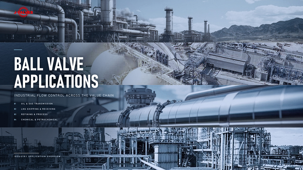
The homes for a 10K CF8 valve are the plants built to Japanese piping classes: water and waste water treatment, HVAC and chilled water, food and beverage processing, pharmaceutical utilities, and shipboard systems where the JIS flange is the yard standard. In all of those the pressure is low, the medium is the deciding factor, and the flange drilling is what has to match the pipe.
It is also the valve that gets specified when a project is built to a Japanese or Korean standard and the buyer wants a stainless body without moving to the ASME system. That is a legitimate reason and it is the reason this page exists, but it comes with the flange caveat: the moment the line is ASME, this valve is the wrong one and the answer is a Class 150 valve with B16.5 flanges.
The valve is not for high pressure, not for large size, and not for a duty that needs two independent barriers. Ten K is a low rating, a floating ball has one barrier, and a two piece body has one joint that cannot be opened under pressure. Those are not limitations to be worked around; they are the design, and a buyer who needs more should be moved to a trunnion valve rather than sold a bigger version of this one.
Installation, Operation and Maintenance
The first installation question is whether the mating flange is JIS 10K. If it is, the joint is straightforward: the gasket goes in, the faces are brought together, and the studs are tensioned in a cross pattern. If the mating flange is ASME Class 150, the valve does not fit and no gasket will help, because the bolt holes do not line up.
The facing has to match as well. A flat face valve goes against a flat face flange with a full face gasket, and a raised face valve goes against a raised face flange with a gasket inside the bolt circle. Mixing the two puts the load in the wrong place and produces a joint that leaks at the first thermal cycle.
The gasket follows the facing. On a flat face joint a full face gasket is used and the bolts pass through it, so the gasket is located by the bolts rather than by the bore; on a raised face joint a gasket that sits inside the bolt circle is correct. For water service at ambient a rubber gasket will do, and for anything above the low temperature band a spiral wound gasket with a graphite filler is the safer default, because it does not take a set and it does not creep.
Operation is a quarter turn, and the locking hole in the lever is there to pin the position. The gland can be adjusted with the valve under pressure because the stem is retained by the body. Anything beyond the gland means taking the single body joint apart, which means isolation, venting and draining first, and a new gasket afterwards.
How to Specify and Order
Five things decide the valve: the size written as 150A, the rating written as 10K, the body grade, the facing, and the seat. The facing is the one most often omitted, and on a JIS valve it is the one that decides whether the joint can be made at all, because flat face and raised face are both common in the same plant.
Three more questions are about the line: the medium, the temperature and the mating flange standard. The medium decides between CF8 and CF8M, the temperature decides between PTFE, reinforced PTFE and PPL, and the mating flange standard decides whether this valve can be used at all.
Documents should be named: EN 10204 3.1 for body, ball and stem, the JIS B2003 test records, the dimensional report with the flange drilling, and the fire test certificate if fire safe is being claimed. On a JIS valve the marking matters as much as the paper, because the size and rating are cast or stamped on the body and that is what the inspector reads first.
FAQ
Q: Is 150A the pressure rating or the size?
A: The size. In the JIS system 150A is a nominal bore of about 150 millimetres, which corresponds roughly to six inch in the imperial system. The pressure rating on this valve is 10K, which is a separate number and a separate unit. A valve is described by both, which is why the page title carries 150A and 10K together.
Q: Is 10K the same as ASME Class 150?
A: No, and the difference is large. Ten K is one megapascal. ASME Class 150 is rated at 19.6 bar at 38 C for a carbon steel body and slightly less for an austenitic one, so Class 150 is close to twice the pressure of 10K. The two ratings are the lowest in their own systems, which is why they get treated as equivalent, but a 10K valve must not be offered as a Class 150 valve.
Q: Will a JIS 10K valve bolt to an ASME Class 150 flange?
A: No. At the same nominal size the two flanges have different bolt circles, different bolt counts and different facing dimensions. A JIS valve needs a JIS flange, and a project that mixes the systems needs an adaptor or a spool piece. This is a piping class question rather than a valve question, and it is cheaper to answer before the valve is ordered.
Q: CF8 or CF8M for this valve?
A: CF8 for water, steam condensate and general service without chlorides. CF8M when there are chlorides, which in practice means seawater, brine and coastal or chemical service. CF3M is the low carbon version of CF8M and is chosen for weldability rather than for corrosion resistance, which matters on a welded body and rarely on a flanged one.
Q: What does a two piece body mean for maintenance?
A: That there is one joint to open and one gasket to replace. The cap comes off and the ball and both seats come out, with the pipe left in place. What it also means is that the joint sees full line pressure, so the valve cannot be opened until the line is isolated and the body is vented and drained.


Hot Products


News
Stainless Steel Ball Valve Grades: 304, 316 And 316L, And What Actually Decides
Molybdenum is the difference that decides the duty, carbon is the difference that gets missed, and the chloride in the line matters more than the price.
Read More
Ball Valve Spare Parts for Overseas Projects: The Wear Part List, The Quantity Math, And Four Traps
Why isolation valves fail on calendar time, not cycles. Wear part lists, Poisson stock maths, seat kit traps and the clauses that decide year six.
Read More
Ball Valves On A Bottom Loading Gantry: Creep, Dry Break And The Test That Proves Neither
A loading gantry cycles a ball valve far more than it is designed for and still cannot prove shut-off. Where creep starts, and what to specify.
Read More
Lined Ball Valves in Acid Service: The Liner Does Not Fail, The Steel Behind It Does
The valve came out of the line looking better than most valves that come out of a hydrochloric acid line. Three inch, PFA lined, cast body, Class 150, fourteen months in service on a 32 percent acid transfer duty at 55 to 60 degrees C, about forty open and close cycles a week. The paint was intact.
Read More