

CHINA J-VALVES Offers Various High-quality I ndustrial Ball Valves
J-VALVES, a distinguished professional ball valve manufacturer rooted in China, takes pride in its extensive product portfolio. Our offerings span a wide range, including trunnion-mounted ball valves, floating ball valves, high-temperature ball valves, high-pressure ball valves, metal-sealed ball valves, ultra-low temperature ball valves, DBB ball valves, Three-way And Four-way Ball Valve, and fully welded ball valves. Each product is a testament to our commitment to precision engineering and reliable performance. Meticulously crafted, they are designed to not only meet but exceed the most stringent industrial demands, ensuring stable operation even under extreme conditions. This enables us to provide our clients with high-value services and makes our valves widely sought-after in industries.
Product Category
Contact Us


-
J-VALVES-Q41F
-
J-VALVES
Overview of the J-VALVES DN100 PN16 CF8M Two Piece Floating Ball Valve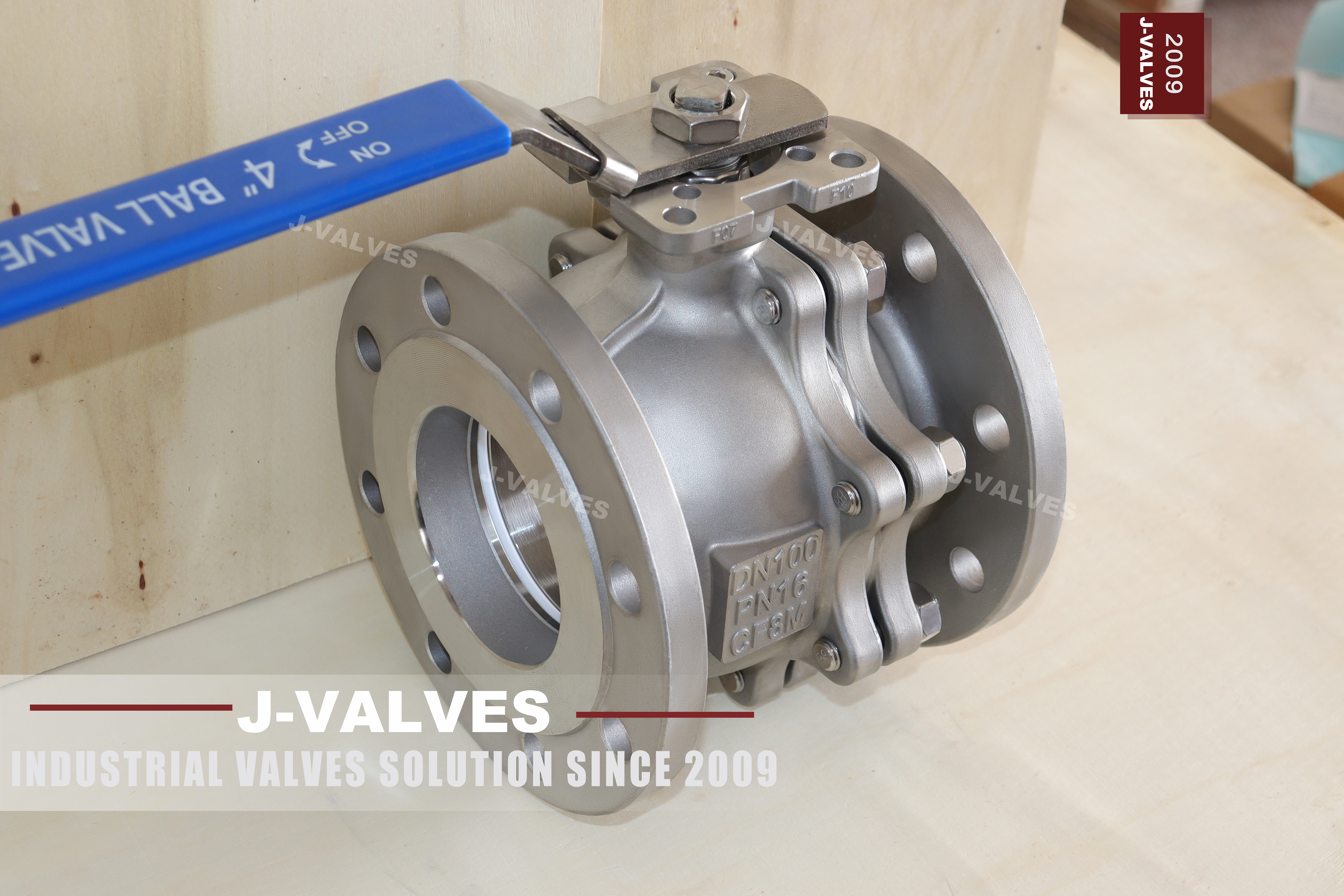
The pressure line on this page reads PN 16 with a note saying equivalent to 10K, and that note is where the trouble starts. The two numbers are not one number written twice. They belong to different flange standards, and at DN100 the two flanges do not share a bolt circle, an outside diameter or a hole size, so a counter flange ordered against one will not fit a valve built to the other. Equal pressure is not equal drilling.
The rest of the specification block makes the same point from the other side. The design code is Japanese, the face to face dimension is Japanese, and the test standard is Japanese, while the flange line offers either a Japanese 10K or a Chinese PN16 drilling. So the valve is built inside one system and labelled with a number from another, and the buyer is left to work out which one the delivery will follow.
This page separates the two. It treats the rating and the flange system as two decisions, says which documents this valve is actually built to, and sets out what a purchase order has to name so that the counter flange and the face to face length both land on the first attempt. No figure here is calculated; the only numbers are the ones the standards print.
Design and Construction
The body is two pieces: a main body and one end cap on a bolted joint, with the joint gasket between them. The ball floats, which means it is not carried on trunnions but held between two seat rings and pushed downstream by line pressure, so the seal is loaded by the medium rather than by a spring set. That is what makes a floating valve simple and what limits it: as the bore grows, the load the ball puts on the downstream seat grows with it, which is why this layout is offered at four inch and not at twenty four.
Each seat ring sits in a pocket cut into the body on one side and the end cap on the other. The ball is in the middle, and when the valve is closed the upstream pressure pushes the ball into the downstream seat while the upstream seat is pushed back by the same pressure. The cavity between the two seats is therefore at line pressure on one side when the valve is closed, and the seat arrangement has to be able to relieve that, or the cavity has to be vented.
The stem comes through the body, is held by the gland, and is squared or keyed to the ball so that turning the lever turns the ball. On this valve the lever has a locking hole, which is a small feature that matters in practice: it allows the valve to be pinned open or closed, so a line that must not be moved by hand can be secured without adding an actuator.

Material Options
The body is cast austenitic stainless, CF8M as standard, with CF3M and CF8 offered as alternatives. The three codes are three different castings rather than three prices: CF8M is the molybdenum bearing grade, CF3M is its low carbon version, and CF8 has no molybdenum. The plate carries one of them and the certificate follows the plate. Where a medium needs something the plate does not name, that is a question for the certificate and the order, not for the product title.
The ball is CF8M, either solid or with a nickel or chrome surface, and the stem is CF8M, a 316 wrought grade, or a precipitation hardening grade where the torque calls for it. The seat list runs PTFE, reinforced PTFE and PPL, and the three set three different temperature ceilings, all of them below the one printed for the body. The packing is PTFE V rings or graphite, and the joint gasket is a spiral wound or a PTFE envelope, chosen with the medium rather than with the pressure.
The bolting is stainless, either a 316 wrought grade or a B8M stud with an 8M nut, which matters on a cast stainless valve because the bolts are the one part that is not the body material and the one part that will show corrosion first on a wet site. On a valve that is washed down or installed outdoors, the bolting is worth naming on the order instead of accepting whatever comes with the standard build.
| Component | Standard Material | Optional Upgrade | Service Notes |
|---|---|---|---|
| Body | CF8M cast austenitic stainless | CF3M or CF8 | code on the plate |
| End cap joint | one bolted joint with a gasket | spiral wound or PTFE envelope | renewed at every break |
| Ball | CF8M, solid | nickel or chrome surface | floats between two seats |
| Stem | CF8M | 316 wrought or a precipitation hardening grade | packing adjustable at the gland |
| Seat | PTFE | reinforced PTFE or PPL | sets the temperature ceiling |
| Packing | PTFE V rings | graphite | adjustable without opening the body |
| Bolting | 316 wrought grade | B8M studs with 8M nuts | the part that corrodes first |
| Flange | raised face | 10K or PN16 drilling, named on the order | drilling decides the counter flange |
| Operator | lever with a locking hole | gearbox, pneumatic or electric | locking hole secures the position |
Technical Specifications
The valve is DN100, four inch, with a PN 16 marking and a raised face flange. The flange line on the page offers a Japanese 10K or 20K drilling or a Chinese PN16 drilling to GB/T 9113, and those are not interchangeable at this size: the bolt circle, the flange outside diameter and the hole size differ, so the counter flange has to be ordered against the same standard as the valve. The pressure number alone does not tell a fabricator which holes to drill.
The face to face length is given to the Japanese standard for this size, which means the valve is a drop in replacement only inside a line laid out to that standard. In a line built to a European face to face series the same nominal size will not necessarily occupy the same space, and the difference shows up as a gap or an interference at installation rather than as a specification error. Both the length and the drilling therefore have to be named on the order, because neither can be corrected on site.
| Item | Value |
|---|---|
| Nominal size | DN100, four inch |
| Pressure class | PN 16 marking, with a Japanese 10K equivalent offered on the page |
| Body style | two piece, one bolted body joint |
| Ball support | floating, held between two seat rings |
| Body material | CF8M cast austenitic stainless, code as stamped |
| Body options | CF3M low carbon or CF8 without molybdenum |
| Ball material | CF8M, solid |
| Ball surface | plain, nickel or chrome on request |
| Stem material | CF8M, with 316 or a precipitation hardening grade as an option |
| Seat material | PTFE as standard |
| Seat options | reinforced PTFE or PPL |
| Packing | PTFE V rings, or graphite on request |
| Body gasket | spiral wound or PTFE envelope |
| Bolting | 316 wrought grade, or B8M studs with 8M nuts |
| End connection | raised face flange, JIS B2220 10K or 20K, or a PN16 drilling to GB/T 9113 |
| Face to face | JIS B2002 for this size |
| Design standard | JIS B2071, with ASME B16.34 and API 608 listed underneath |
| Test standard | JIS B2003 or API 598, named on the order |
| Shell test | one and a half times the rating |
| Seat test | one and a tenth times the rating, both directions |
| Seat acceptance | no visible leakage, because the seat is soft |
| Temperature range | minus 29 to plus 425 Celsius on the body, metal temperature |
| Temperature ceiling | set by the seat and the packing |
| Operation | lever with a locking hole, actuator mounting on request |
| Drilling note | PN 16 and 10K do not share a bolt circle at this size |
| Order note | name the flange standard and the face to face standard, not only the pressure |
Standards and Compliance
The page lists a Japanese design code, the general steel ball valve standard and the American pressure boundary standard together, and adds a Japanese test standard next to the American one. They overlap but they do not agree on everything, so an order that names all of them has to say which one governs. The practical rule is that the design code decides the wall and the dimensions, the pressure boundary standard decides the rating, and the test standard decides what the certificate says was done.
The test line is worth reading twice, because this valve can be tested to either a Japanese or an American procedure. The two apply the same multiples, one and a half times the rating for the shell and one and one tenth for the seat, but the record they produce is a different document. A buyer who needs one of them for a package should name it, because a certificate to the other will be queried by whoever reviews the dossier, even though the valve passed the same pressures.
| Requirement | Standard | What J-VALVES Supplies |
|---|---|---|
| Design | JIS B2071 | wall and dimensions |
| Pressure boundary | ASME B16.34 | rating |
| General ball valve | API 608 | overlapping requirements |
| Flange | JIS B2220 10K or 20K | or a PN16 drilling, named on the order |
| Face to face | JIS B2002 | value stated in the size table |
| Testing | JIS B2003 or API 598 | named, and the record differs |
| Marking | plate and certificate | size, rating, code, heat |
Manufacturing Process
The body and the end cap are cast, cleaned and then machined from the flange faces, so that the bore, the seat pockets and the joint face are cut from one reference. The joint face is finished before the seat pocket is cut from it, because a pocket cut from a rough face is square to nothing, and a seat that is not square to its pocket will leak on one side of the ring before it seats on the other. The ball is machined and then polished, since the surface the seat runs against is the seat.
Assembly puts the ball between two seat rings, closes the end cap on a new gasket, and takes the studs down in a cross pattern so that the joint closes evenly. The gasket is a consumable: it is renewed every time the joint is opened, which on a floating valve is every time a seat is changed. That is a cost the buyer meets repeatedly, and it belongs in the store rather than in the workshop, because a valve held open for want of a gasket is a line held down for want of a gasket.

Quality Control and Testing
The casting is checked against the heat number on the plate, and a material identification report is issued against the same heat when the order asks for one. The check matters on a cast stainless valve because CF8, CF8M and CF3M come out of the foundry looking the same and only the plate and the certificate separate them. The certificate follows the plate; it does not replace reading the plate at goods in.
The shell test runs at one and a half times the rating with the body assembled, so the joint is tested with the wall. The seat test follows at one and one tenth times in both directions, and on a floating valve the acceptance is no visible leakage, because the seat is soft and has the resilience a metal seat does not. A soft seat that is allowed a rate is a soft seat that has been specified as something it is not.
| Step | What Is Checked | Standard or Acceptance |
|---|---|---|
| Casting | heat number and certificate | read against the plate code |
| Material identity | report against the same heat | quoted when the order asks |
| Joint face | finished before the seat pocket | pocket square to the face |
| Flange | measured to the named drilling | not to the pressure number |
| Shell test | wall and joint at 1.5 times | run with the joint assembled |
| Seat test | both directions at 1.1 times | no visible leakage on a soft seat |
| Marking | plate, certificate and drawing | size, rating, code, heat |

Applications and Industry Service
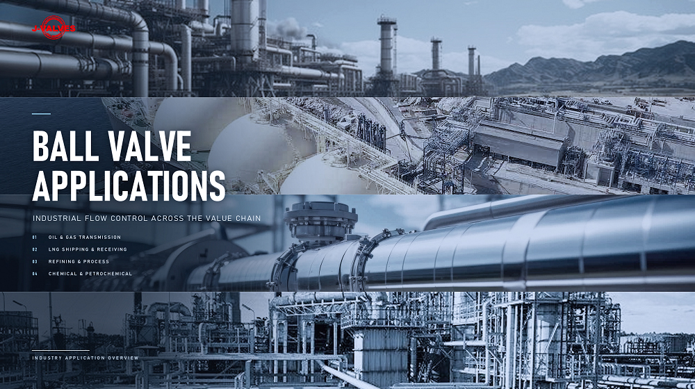
A floating valve at this size suits water, chilled water, compressed air, and light chemical transfer where the pressure is moderate and the medium is clean. It is the standard choice on plant utilities, on skids that are built to a Japanese dimensional series, and on lines where the valve is operated daily and a soft seat gives the tightness that a process needs. The lever with a locking hole makes it usable as a secured isolation point without an actuator.
It is the wrong valve where the pressure is high enough to load the ball hard against the downstream seat, because that is what a trunnion design is for, and where the medium carries solids that would sit between the ball and the seat. It is also the wrong choice where the line has to be pigged, since a floating valve of this size is not a pig trap, and where the piping is laid out to a European face to face series that this valve does not follow.
Installation, Operation and Maintenance
Installation is a matter of matching three things at once: the flange drilling, the gasket and the length. The gasket has to suit the facing, the bolting has to suit the flange, and the valve has to fit the space the line leaves. Getting the first two right and the third wrong is the common failure, and it is the one that cannot be fixed with a spanner. Check the face to face against the standard the line was built to before the valve leaves the store.
In service the valve is either open or closed and should not be used to throttle, because a partly open floating ball puts the seat on the edge of the port and erodes it. A seat change needs the line isolated and the joint opened, and the gasket renewed at the same time. The stem packing can be adjusted at the gland without opening the body, which is the only maintenance this valve allows with the line still full.
How to Specify and Order
The order has to name the size, the rating, the flange standard and the drilling, the facing, the face to face standard, the body code, the ball, the seat, the packing, the operator and the test standard. Of those, the flange standard and the face to face standard are the two that decide whether the valve fits, and both are separate from the pressure number. Writing PN 16 and stopping there leaves the drilling and the length open, which is how a valve arrives that matches the pressure and not the pipe.
The sentence to put on the enquiry is short: DN100, PN 16, flange drilling to be confirmed as 10K or PN16 and stated on the drawing, face to face to the same standard as the line, test to be named. That one line removes the ambiguity the page leaves. If the line is Japanese, order the Japanese drilling and the Japanese length; if it is European, both have to change together, because changing one and not the other produces a valve that fits nowhere.
FAQ
Q: Is PN 16 the same as 10K?
A: No. They are two ratings from two flange standards, and at DN100 the flanges do not share a bolt circle, an outside diameter or a hole size. A counter flange drilled to one will not fit a valve built to the other. The pressure they represent may be the same order of magnitude, but the drilling is a physical interface and has to be named on the order.
Q: Which standard is this valve actually built to?
A: The design, the face to face length and the test on this page are Japanese. The flange is offered either as a Japanese 10K or 20K drilling or as a Chinese PN16 drilling, and that choice is made on the order. So the valve is built inside one system and can be fitted with a flange from another, which is exactly why the order has to say which.
Q: Will it replace an existing DN100 PN16 valve in a European line?
A: Only if the face to face length matches what the line was built to. The length here follows the Japanese standard for this size, and a line laid out to a European series may leave a different space. Check the length and the drilling against the pipe before the valve is ordered, because neither can be corrected on site once the valve is cast and machined.
Q: Why does a soft seat have to hold zero leakage?
A: Because PTFE and its reinforced versions have the resilience to conform to a mark on the ball, so a leak is a defect rather than a characteristic. A metal seat is judged against a rate for the opposite reason. Applying a rate to a soft seat accepts a valve that is already damaged, and applying zero to a metal seat rejects a valve that is behaving correctly.
Q: Can the valve be locked open or closed?
A: Yes, the standard lever has a locking hole, which allows the position to be pinned. That matters on a line that must not be moved by hand, such as an isolation point on a shared header, where the alternative would be to fit an actuator for a valve that is operated twice a year. The lever is also the cheapest operator, so it is the default until the torque or the duty says otherwise.
Q: What has to be on the order for this valve?
A: The size, the rating, the flange standard and drilling, the facing, the face to face standard, the body code, the seat, the packing, the operator and the test standard. The flange and the length are the two that decide whether it fits, and neither is implied by writing PN 16. Name both, and name which test record the project wants to receive.


Hot Products


News
Ball Valves On A Bottom Loading Gantry: Creep, Dry Break And The Test That Proves Neither
A loading gantry cycles a ball valve far more than it is designed for and still cannot prove shut-off. Where creep starts, and what to specify.
Read More
Lined Ball Valves in Acid Service: The Liner Does Not Fail, The Steel Behind It Does
The valve came out of the line looking better than most valves that come out of a hydrochloric acid line. Three inch, PFA lined, cast body, Class 150, fourteen months in service on a 32 percent acid transfer duty at 55 to 60 degrees C, about forty open and close cycles a week. The paint was intact.
Read More
Ball Valves in Amine CO2 Capture: Heat Stable Salts, Rich Amine, And The Three Places The Body Thins
Rich amine at 110 C with heat stable salts is where capture plant ball valves fail. Materials, velocity limits, cavity gas and seat choice, with numbers.
Read More
Fail-Safe Ball Valve Actuators: Spring Return, Stored Air, And The Torque Nobody Checks
Spring return or stored air? The answer is a torque curve, not a datasheet box. Sizing, receiver volume, closing time and four silent failures.
Read More