


CHINA J-VALVES Offers Various High-quality I ndustrial Ball Valves
J-VALVES, a distinguished professional ball valve manufacturer rooted in China, takes pride in its extensive product portfolio. Our offerings span a wide range, including trunnion-mounted ball valves, floating ball valves, high-temperature ball valves, high-pressure ball valves, metal-sealed ball valves, ultra-low temperature ball valves, DBB ball valves, Three-way And Four-way Ball Valve, and fully welded ball valves. Each product is a testament to our commitment to precision engineering and reliable performance. Meticulously crafted, they are designed to not only meet but exceed the most stringent industrial demands, ensuring stable operation even under extreme conditions. This enables us to provide our clients with high-value services and makes our valves widely sought-after in industries.
Product Category
Contact Us


-
J-VALVES-Q41F
-
J-VALVES
Overview of the J-VALVES API6D DN80 WCB 2 Piece Floating Ball Valve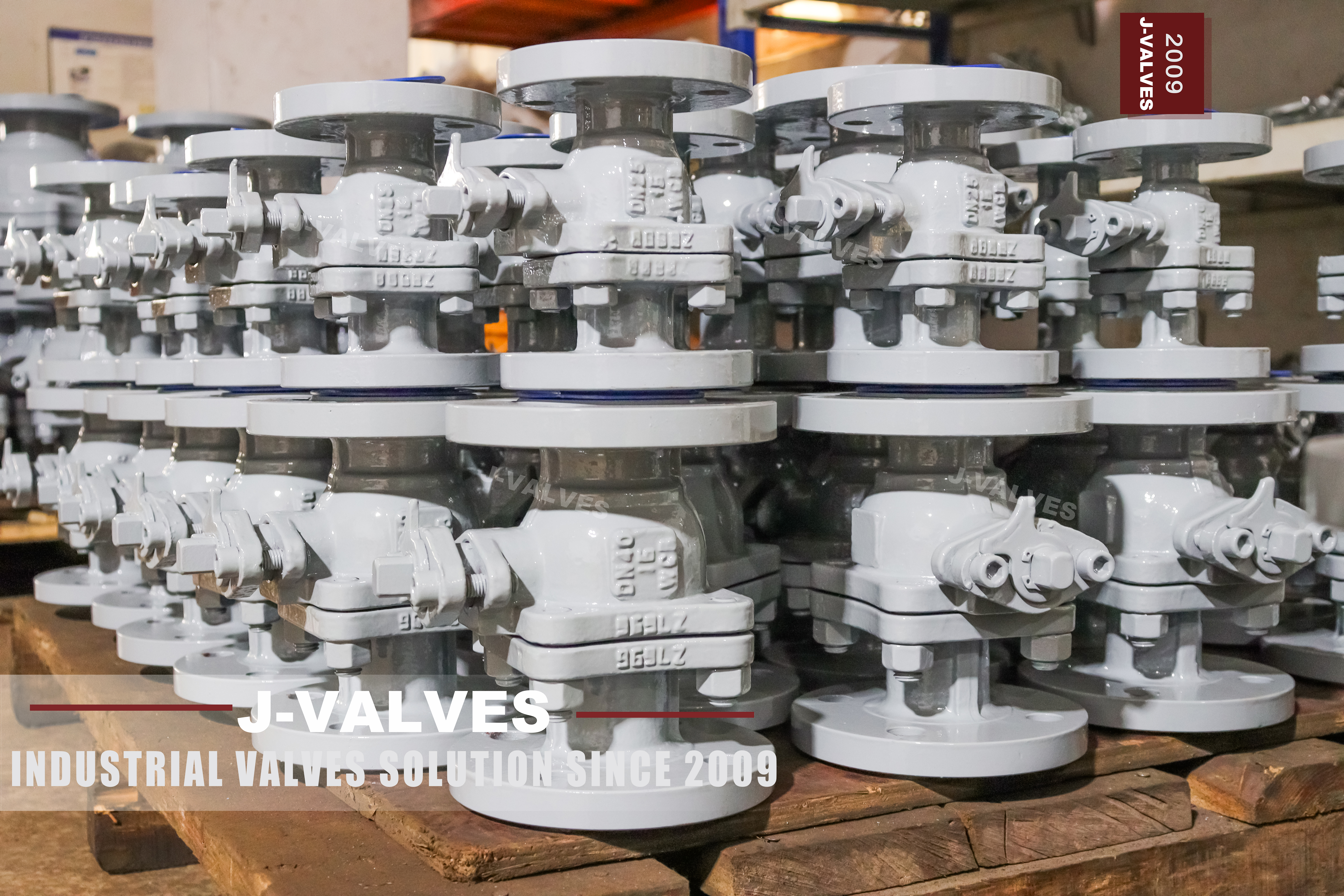
This page covers a range rather than a valve. It offers a three inch two piece floating ball valve at PN16 and at PN25, builds it to ASME B16.34 with API 608 details, and calls it an API 6D valve. A range is a catalogue entry, not a purchase order: two classes and two standards have been folded into one description, and the buyer still has to answer the question of which one is on the skid. That question is worth taking seriously here because the answer is not visible from outside.
At DN80 the two European classes land on the same bolt circle, so a fitter looking at the flange cannot tell a PN16 valve from a PN25 one. The difference between them is in the wall and in the pressure at which the valve was tested, and both of those are recorded rather than seen. That makes the plate and the test certificate the only two documents that settle it, and it makes the order line the place where the range has to be closed down to one class.
Design and Construction
Two piece means the body is split into a main body and one end piece, with a single bolted joint between them. That joint is a pressure boundary and gets the same shell test as the wall, and it is also the only opening through which the ball, the seats and the stem assembly can be reached. On a three inch valve that is the right compromise: one joint is enough access, and one more joint would be one more place to leak on a valve that is bought for its low cost rather than for its serviceability.
The ball floats. It is not carried on trunnions, so line pressure pushes it into the downstream seat and the sealing force rises with the pressure. That is the whole appeal of the design at this size: no bearings, no springs behind the seats, a short passage and a body that can be cast in one pattern. The seat rings are the only parts that move, and they are also the parts that decide how hot the valve can run.
The operator is a lever with a locking device, which on a small isolation valve is not an accessory. The lock is what allows the valve to be padlocked open or closed for a permit to work, and a lever without one turns a line that is supposed to be isolated into a line that is isolated until somebody walks past. A gearbox, a pneumatic actuator or an electric actuator are available where the valve is out of reach or part of a sequence, and each is a separate line on the order.

Material Options
The body is WCB, a cast carbon steel, which is the default for water, oil and gas at ordinary temperature where nothing in the medium attacks it. A105 forged steel is offered where a higher strength body is wanted, and A350 LF2 where the valve has to work below the carbon steel limit. Each of those is a different body rather than an upgrade to the same one, and the code on the plate is the only statement this page makes about which was supplied.
The ball is WCB or A105 with an electroless nickel or hard chrome deposit, which gives a hard sealing surface over a cheap base. The stem is A105 with a deposit, 17-4PH or a 420 stainless, and the choice is written on the order rather than taken from the body code. The seat is PTFE or reinforced PTFE as standard, with PPL or a metal seat with flexible graphite where the temperature runs beyond what a polymer seat will take.
The seat is the part that limits the service, not the body. A carbon steel body with a PTFE seat is a valve for water and oil at ordinary temperature; the same body with a metal seat reaches further up the temperature scale, but the torque rises and the leakage class changes with it. That is why the seat material belongs on the same line of the order as the temperature, and why a page that states one temperature range for the whole valve is stating the boundary rather than the usable range.
| Component | Standard Material | Optional Upgrade | Service Notes |
|---|---|---|---|
| Body and end piece | WCB cast carbon steel, code as stamped | A105 forged or A350 LF2 on order | one bolted body joint |
| Ball | WCB or A105 with ENP or hard chrome | stainless on order | floats into the downstream seat |
| Stem | A105 with a deposit | 17-4PH or 420 stainless on order | through the body |
| Seat ring | PTFE or reinforced PTFE | PPL or metal with flexible graphite | sets the temperature ceiling |
| Packing | flexible graphite or PTFE V rings | named on the order | tightened from outside |
| Body joint gasket | spiral wound or ring joint | named on the drawing | new gasket at every break |
| Bolting | A193 B7 with A194 2H nuts | B8M with 8M nuts on order | grade on the order |
| Operator | lever with locking device | gearbox, pneumatic or electric on request | lock for a permit to work |
Technical Specifications
The flange is raised face, either to EN 1092-1 at PN16 or PN25 or to ASME B16.5 where the line is American. The two systems are not interchangeable: a PN16 flange and a Class 150 flange are close in pressure but differ in bolt circle, bolt count and facing detail, so the standard is written on the order separately from the class. At DN80 the European PN16 and PN25 patterns fall on the same bolt circle, which is exactly why the flange cannot be used to identify the class.
Face to face follows ASME B16.10 for a flanged valve of this size and class, and the figure for a particular build is dimensioned on the signed general arrangement drawing. Where butt weld ends to ASME B16.25 are ordered instead of flanges, the end to end length changes and the drawing carries the welded dimension. API 6D lists both flanged and welded ends as within its scope; it does not recommend one over the other, and the choice belongs to the piping design.
The catalogue offers full bore and reduced bore. Full bore is the standard build and it is what makes the valve piggable and low in pressure drop; reduced bore saves weight and cost and is a different ball and a different body passage. At three inch the price difference is small, so the decision is about the line rather than about the budget: a line that will ever be pigged or swept needs the full bore.
| Item | Value |
|---|---|
| Nominal size | DN80 (NPS 3) |
| Pressure class | PN16 or PN25, one class per order |
| Body style | two piece, one bolted body joint |
| Ball support | floating, self energised by line pressure |
| Bore | full bore as standard, reduced bore on order |
| Body material | WCB cast carbon steel, catalogue code as stamped |
| Body options | A105 forged steel or A350 LF2 on order |
| Ball material | WCB or A105 with ENP or hard chrome |
| Stem material | A105 with a deposit, or 17-4PH, or 420 stainless |
| Seat material | PTFE or reinforced PTFE as standard |
| Seat options | PPL, or a metal seat with flexible graphite |
| Packing | flexible graphite or PTFE V rings |
| Body joint gasket | spiral wound or ring joint, named on the drawing |
| Bolting | A193 B7 with A194 2H nuts, or B8M with 8M nuts |
| End connection | raised face flange to EN 1092-1, or ASME B16.5 |
| End alternative | butt weld ends to ASME B16.25 |
| Face to face | dimension on the signed GA drawing, held to ASME B16.10 |
| Operation | lever with a locking device |
| Operation options | gearbox, pneumatic or electric actuator on request |
| Design standard | ASME B16.34 and API 608, with API 6D |
| Test standard | API 598 shell and seat test |
| Test pressure | shell 1.5 times and seat 1.1 times the ordered class |
| Temperature range | minus 29 to plus 425 Celsius, metal temperature |
| Temperature ceiling | set by the seat material, not by the body code |
| Class marking | the plate and the test record, not the flange at this size |
| Documentation | EN 10204 3.1 on request |
Standards and Compliance
ASME B16.34 gives the pressure boundary and the rating table, API 608 gives the ball valve specific test and marking requirements, and API 6D adds the pipeline valve requirements on top of both. A valve can legitimately be built to 608 and not to 6D; what 6D adds is the pipeline documentation set, the marking and the requirement that the valve be traceable to a specification, not a heavier casting. That is why the same DN80 body appears under both standards in catalogues.
The class the valve is ordered at sets the test pressure, because API 598 puts the shell test at one and a half times the rating and the seat test at one and one tenth times. A PN16 valve and a PN25 valve of the same size are therefore tested at different pressures and their certificates carry different numbers, which is the second place, after the plate, where the class is recorded. Where fire safe construction is required, the test standard has to be named, because API 607, API 6FA and ISO 10497 are different tests.
| Requirement | Standard | What J-VALVES Supplies |
|---|---|---|
| Pressure boundary | ASME B16.34 | minimum wall and the rating at temperature |
| Ball valve items | API 608 | shell and seat test, marking |
| Pipeline valve | API 6D | design, marking, documentation and traceability |
| Shell and seat test | API 598 | 1.5 times the ordered rating, 1.1 times for the seat |
| Flange pattern | EN 1092-1 PN16 or PN25 | raised face; ASME B16.5 on request |
| Face to face | ASME B16.10 | flanged valve length for the size and class |
| End connection | ASME B16.5 or B16.25 | both within API 6D scope, neither recommended |
| Fire test | API 607, 6FA or ISO 10497 | named on the order, not interchangeable |
| Documentation | EN 10204 3.1 | issued against the heat number on request |
Manufacturing Process
The body and the end piece are cast from the same pattern and the same heat, then machined from the flange faces inward. The flange is faced and drilled, the bore is machined through, and the body joint face and the seat pockets are cut from the machined datum so that the pocket stays square to the surface it seals against. On a valve of this size the machining is done in one or two setups and the tolerances are what decide whether the ball seats without lapping.
Assembly puts the ball and the two seat rings into the main body, offers the end piece up on a new gasket, and brings the joint down with the studs in a cross pattern. The stem goes in through the body, the lever goes on the stem, and the valve is cycled by hand before it goes to test. The lever stops are set so that the ball is square to the bore at both ends of travel, because a lever that over-travels a few degrees on a floating valve loads one seat and unloads the other.

Quality Control and Testing
The shell test is run at one and a half times the rating of the class that was ordered, which is where the PN16 and PN25 builds separate: the same body is proved to two different pressures and the record states which. The body joint is watched along with the wall. The seat test follows in both directions at one and one tenth times the rating, with the downstream side open so that a seat leak cannot hide behind a trapped volume in the cavity.
After testing, the valve is cycled and the lever torque is felt by hand, the lock is checked to see that it holds the lever in both end positions, and the plate is read against the certificate. The plate carries size, class, body code and heat number; if it carries a class that does not match the test record, the valve is not the valve that was ordered, and at this size the mistake is cheap to make because the castings are the same.
| Step | What Is Checked | Standard or Acceptance |
|---|---|---|
| Casting | code, heat number, certificate | checked against the stamped code |
| Flange faces | flatness and finish on both ends | raised face height checked |
| Seat pockets | square to the joint and flange faces | cut in the same setup as the face |
| Assembly | joint faces parallel before torque | cross pattern from the drawing |
| Shell test | body joint and wall at the ordered class | API 598 at 1.5 times that class |
| Seat test | both directions, downstream open | API 598 at 1.1 times, no visible leak |
| Lever and lock | quarter turn stops, lock in both ends | checked by hand before packing |
| Marking | plate class against the test record | the only place the class is written |

Applications and Industry Service
This valve belongs on water, oil and gas lines at ordinary temperature, at three inch, where the duty is isolation rather than control: utility water, cooling circuits, instrument and utility air, small process branches, tank farm connections, and the isolation point in front of a control valve or a strainer. It is operated by hand a few times a shift or a few times a year, and it sits at one end of travel in between, which is the duty a floating ball does well.
It is the wrong valve where the medium carries solids, because the cavity between the seats collects them and the body joint is the only way in. It is the wrong valve for throttling, because a floating ball has no characterised trim and the seat wears at part travel. And it is the wrong valve where the temperature runs beyond the seat, because the body code says nothing about the seat and a carbon steel body with a polymer seat is a valve for ordinary temperature only.

Installation, Operation and Maintenance
The valve can be carried on the pipe at this size, and it is installed with the lever able to swing clear through a quarter turn and with the lock accessible from the walkway. Flanges are brought parallel before the studs are tightened and the studs are torqued in a cross pattern. Where the valve is an isolation point for a permit, the lock is what makes the isolation real, and the procedure should say that the lever is padlocked rather than that the valve is closed.
Maintenance is a body joint and a seat change. With the line isolated and the body drained, the end piece studs are released in a cross pattern, the end piece comes off, and the ball and both seat rings come out. The gasket is replaced, the bore is checked for scoring, and the joint is remade to the drawing torque. The stem packing can be tightened from outside while the valve is in service, and on a valve that is cycled often that is the item that needs attention first.
How to Specify and Order
The order line needs size, class, flange standard, body style, body code, bore, seat material, end connection, operator and test standard. The class is written as one number, not as a range, because a range leaves the test pressure and the plate undecided and the two buildings it produces are not interchangeable on a line that was designed for the higher one. If both classes are wanted, that is two order lines and two plates.
Where the valve is bought for stock rather than for a project, the class has to be fixed on the stock line as well, because a shelf position labelled with two classes will be picked wrong eventually. One part number per class, one plate per valve, and a test record filed against the part number is what keeps a utility store honest. The cost of holding two lines is small next to the cost of a PN16 valve turning up in a PN25 pipe.
FAQ
Q: Why can the flange not tell me whether it is PN16 or PN25?
A: Because at DN80 the two European patterns fall on the same bolt circle with the same facing, so the flange face looks identical whichever class was ordered. What differs is the wall and the pressure at which the valve was tested, and both of those are recorded rather than seen. That is why the plate and the certificate are the only reliable identification on this valve, and why the order should name one class rather than a range.
Q: What actually changes between a PN16 and a PN25 valve of this size?
A: The wall the body has to carry and the pressure at which the shell and seat tests are run. The casting pattern can be the same, which is why the same valve appears under both classes in a catalogue. If the line was designed for PN25, fitting a PN16 valve leaves the line with a component that was never proved at the design pressure, and the plate is the only place that shows it.
Q: Is this valve API 6D or API 608?
A: It can be either, and the catalogue page lists both. API 608 covers metal ball valves and gives the test and marking requirements for them. API 6D adds the pipeline valve requirements on top, including the documentation set and the traceability. What 6D does not do is make the body heavier or the casting different, so the difference between the two builds is in the paper and the marking rather than in the metal.
Q: Can a floating ball valve be used for throttling?
A: No. A floating ball has no characterised trim and no defined flow area between the ends of its stroke, so using it to trim flow gives an unstable curve and wears the seat where it sits at part travel. The valve is a shutoff device: it is either at an end position or it is in transit. Where flow has to be controlled, a control valve with a proper trim belongs upstream of this one.
Q: Why does the lever have a locking device?
A: Because at this size the valve is often the isolation point for a permit to work, and a lever that can be moved by anyone walking past is not an isolation. The lock lets the lever be padlocked in either end position, which is what the procedure needs to be true. A gearbox or an actuator is available where the valve is out of reach, but on a hand operated valve the lock is the part that turns a closed valve into an isolated one.
Q: What has to be on the plate?
A: Size, class, body code and heat number, and on this valve the class is the entry that matters. The plate is the only document on the valve that states the class that was actually supplied, because the flange looks the same at PN16 and PN25. The heat number is the link to the certificate, and the code is the link to the material record, so all four entries are read together rather than one at a time.


Hot Products


News
Ball Valves in Amine CO2 Capture: Heat Stable Salts, Rich Amine, And The Three Places The Body Thins
Rich amine at 110 C with heat stable salts is where capture plant ball valves fail. Materials, velocity limits, cavity gas and seat choice, with numbers.
Read More
Fail-Safe Ball Valve Actuators: Spring Return, Stored Air, And The Torque Nobody Checks
Spring return or stored air? The answer is a torque curve, not a datasheet box. Sizing, receiver volume, closing time and four silent failures.
Read More
Ball Valve Stem Leak: The Gland, The Backseat And The Repair That Cannot Be Done Live
A stem leak on a quarter turn valve is four different failures. What gland tightening buys you, why the backseat is usually absent, and what needs a shutdown.
Read More
Ball Valves in A Kraft Pulp Mill: Black Liquor, Green Liquor And The Cost of Choosing The Alloy by Habit
White liquor at pH 14 cracks carbon steel welds, black liquor sets solid below 100 C, green liquor dregs grind seats: alloy choice and torque in a kraft mill.
Read More