


CHINA J-VALVES Offers Various High-quality I ndustrial Ball Valves
J-VALVES, a distinguished professional ball valve manufacturer rooted in China, takes pride in its extensive product portfolio. Our offerings span a wide range, including trunnion-mounted ball valves, floating ball valves, high-temperature ball valves, high-pressure ball valves, metal-sealed ball valves, ultra-low temperature ball valves, DBB ball valves, Three-way And Four-way Ball Valve, and fully welded ball valves. Each product is a testament to our commitment to precision engineering and reliable performance. Meticulously crafted, they are designed to not only meet but exceed the most stringent industrial demands, ensuring stable operation even under extreme conditions. This enables us to provide our clients with high-value services and makes our valves widely sought-after in industries.
Product Category
Contact Us


-
J-VALVES-Q41F
-
J-VALVES
Overview of the J-VALVES DN25 PN100 F304 Stainless Steel High Pressure Floating Ball Valve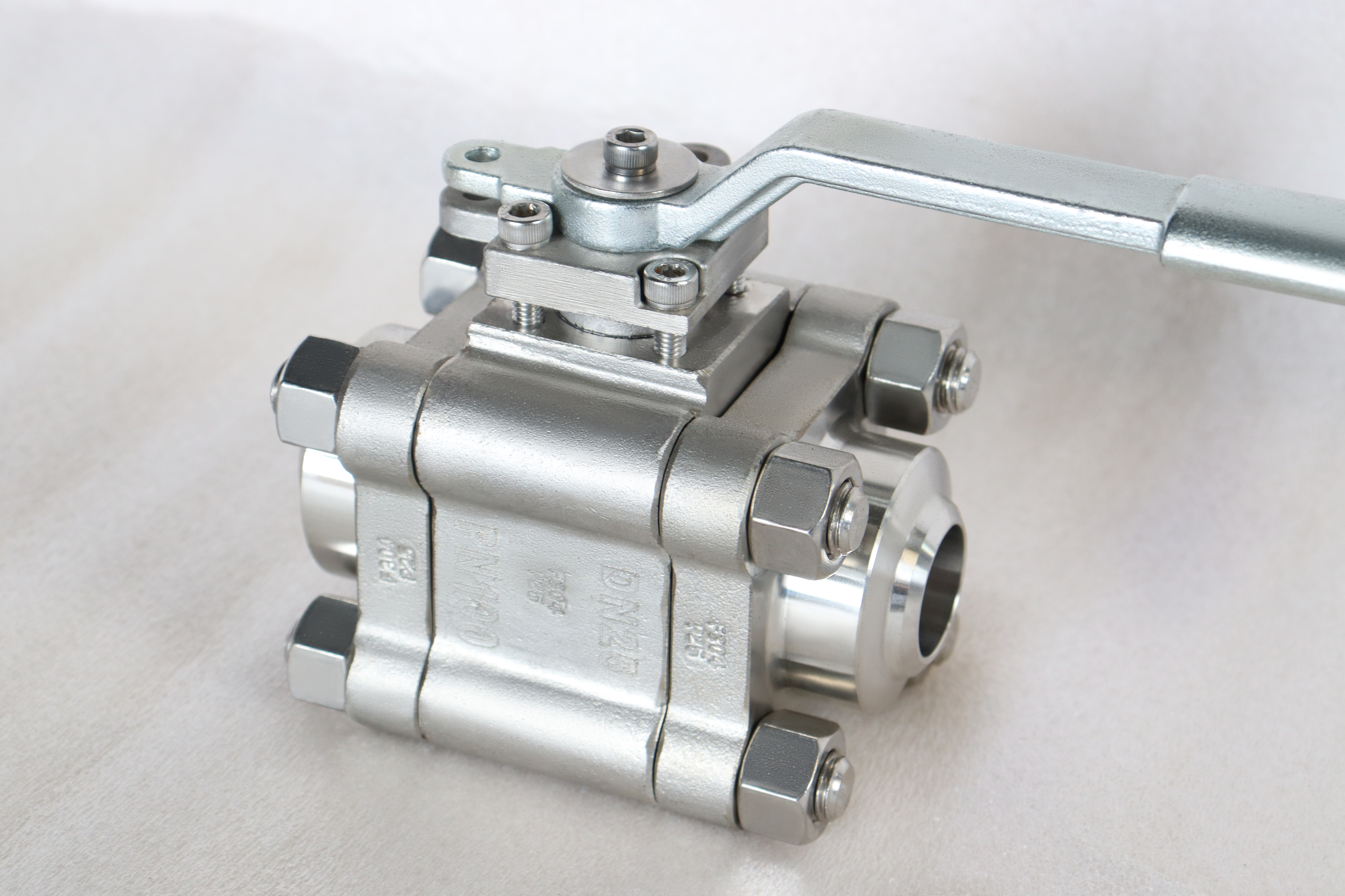
Nearly every product page on this site carries the same temperature line, and it reads minus twenty nine to plus four hundred and twenty five Celsius. On a carbon steel valve that line is correct: it is where the standard carbon steel body sits, and the upper figure is the ceiling of a carbon steel shell. On this valve, which is a stainless body with a polymer seat, both numbers are wrong in different directions.
The lower one is merely conservative. An austenitic stainless does not become brittle at the temperature where carbon steel does, so the floor it is being given is not its floor. The upper one is the dangerous half: four hundred and twenty five Celsius is far beyond what a PTFE seat will take, and a buyer who reads that line and puts the valve on a hot line has bought a valve that will not hold.
Design and Construction
Three pieces with two bolted joints, the ball floating between two seats and the trim coming out through the middle section. The construction is ordinary for a one inch high pressure valve, and it exists so that the seat, which is the part that wears, can be replaced without cutting the line. The body is forged, which at this size is the normal way to make a high pressure body without the porosity a casting would carry.
At Class 600 the ball is small and the seat load is high relative to the size, which is the reason a soft seat on this valve is a decision rather than a default. The pressure pushes the ball into the downstream seat, and the seat has to be supported so that it does not extrude into the clearance around it. That support, rather than the body material, is what the pressure class is actually asking for.

Material Options
The body code is F304, a forged austenitic stainless steel, and one of the properties that comes with the austenitic family is that it stays ductile at low temperature where a carbon steel becomes brittle. That is why the minus twenty nine figure on the page is not this valve floor: the alloy was never limited by it, and the figure arrived from the template rather than from the material.
The seat is PTFE as standard, with reinforced PTFE or PPL available and a metal seat on request. The seat is where the upper limit comes from, and it is a much lower ceiling than four hundred and twenty five Celsius. That is the one number on the page that has to be replaced with the actual seat material and its actual limit before the valve is offered for a hot line.
| Component | Standard Material | Optional Upgrade | Service Notes |
|---|---|---|---|
| Body | F304 forged stainless steel, code as stamped | another stainless code on order | austenitic, ductile at low temperature |
| Ball | F304 with a hard surface | named on the order | floats into the downstream seat |
| Stem | F304, or a higher strength alloy on order | named on the order | retained by the body cover |
| Seat ring | PTFE | reinforced PTFE, PPL or metal | sets the temperature ceiling, not the body |
| Seat support | checked at assembly | part of the Class 600 design | a seat without it extrudes before it wears |
| Body joints | two gasketed studded joints | not offered as a welded body | new gasket at every break |
| End facing | raised face to ASME B16.5 | chosen at order | Class 600 pattern |
| Operator | lever | gear or actuator on request | handle must clear the pipe |
Technical Specifications
At one inch the tables are short enough to memorise, which is why the errors on this size happen elsewhere. The flange is an ASME B16.5 Class 600 raised face pattern at one inch, the bore is full, and the face to face follows ASME B16.10 for a flanged valve of this size and class; the built length is on the signed drawing. Class 600 is PN 100 in the API 6D code. The figure that is usually copied wrongly onto this valve is the temperature rather than the pressure, because the two rows look alike on a data sheet and mean different things.
The temperature column is the one to read carefully, because it is not a single value but a table: the rating falls as the temperature rises, and the table that governs the fall is grouped by material. A stainless body is in a different group from a carbon steel one, so the two do not share a rating curve even at the same class. The page prints one line for both, which is the error this page is describing.
| Item | Value |
|---|---|
| Nominal size | 1 inch (DN25) |
| Pressure class | Class 600 (PN 100, the API 6D pressure code) |
| Body style | three piece, two gasketed body joints |
| Ball support | floating, no trunnion |
| Bore | full bore |
| Body material | F304 forged stainless steel, code as stamped |
| Ball material | F304 with a hard surface |
| Stem material | F304 or a higher strength alloy, stated on the order |
| Seat material | PTFE as standard |
| Seat options | reinforced PTFE, PPL or metal seat |
| Temperature range printed | minus 29 to plus 425 Celsius, a carbon steel figure |
| Lower limit | not set by an austenitic stainless, which stays ductile |
| Upper limit | set by the seat, well below the printed figure |
| Rating basis | ASME B16.34 by material group, not one range for all valves |
| End connection | raised face flange, ASME B16.5 Class 600 |
| Face to face | dimension on the signed GA drawing, held to ASME B16.10 |
| Design standard | ASME B16.34 and API 608 |
| Test standard | API 598 shell and seat test |
| Test pressure | shell 1.5 times and seat 1.1 times the class rating |
| Test temperature | ambient, which is why the test does not support the upper figure |
| Seat support | checked at assembly, part of the Class 600 design |
| Operation | lever |
| Marking | size, class, body code, heat number |
| Documentation | EN 10204 3.1 on request |
Standards and Compliance
ASME B16.34 publishes the pressure temperature ratings by material group, and the grouping is the whole point: a stainless body at Class 600 does not have the same allowable pressure at a given temperature as a carbon steel body of the same class. API 608 is the quarter turn product standard that governs this valve, and API 598 sets the shell and seat acceptance figures. At one inch the rating question is settled quickly and the temperature question is the one that takes the time, which is the reverse of how a larger valve behaves.
None of the three documents supplies a single range for all valves, which is why a range printed on a product page is always a summary of something else. The summary that has been applied here belongs to carbon steel. On a stainless valve the correct statement is the material group, the class and the seat material, and the range follows from those three rather than preceding them.
| Requirement | Standard | What J-VALVES Supplies |
|---|---|---|
| Pressure boundary | ASME B16.34 | rating by material group, so stainless and carbon steel differ |
| Quarter turn product | API 608 | the governing product standard at this size and class |
| Shell and seat test | API 598 | 1.5 times the rating for the shell, 1.1 times for the seat |
| Flange pattern | ASME B16.5 Class 600 | one inch, raised face |
| Face to face | ASME B16.10 | flanged valve length for the size and class |
| Pressure code | API 6D clause 7.2 | Class 600 is written PN 100 |
| Temperature range | not a standard figure | follows the material group and the seat |
| Marking | API 608 and the order | size, class, body code, heat number |
| Documentation | EN 10204 3.1 | issued against the heat number on request |
Manufacturing Process
The body sections are forged and machined, with the joint face and the seat pockets cut from one datum so the two seats stay coaxial, and the flange face finished last. At one inch the body is small enough that the whole machining operation is a single setup on each half, which is how the pockets stay in line. At this diameter the whole operation on each half is one setup, which is what keeps the two seat pockets in line.
Assembly is the ball and seats into one section, the middle section closed over new gaskets, the studs brought down in a cross pattern, then the stem and the lever, then cycling, then test. The seat support is checked before the section is closed, because a seat that is not supported at Class 600 will extrude before it wears, and that is a failure that shows as a leak rather than as a worn part.

Quality Control and Testing
The shell test is at one and a half times the rating and the seat test at one and one tenth times in both directions with the cavity open. Both are run at ambient temperature, which is worth stating because it explains why a test sheet cannot support the top of a temperature range: the valve has never been at four hundred and twenty five Celsius when it was tested.
What the test sheet does establish is that the seats hold and both boundaries are tight at ambient, which is the baseline. The temperature claim has to be supported by the seat material document rather than by the test, and on this valve that document is the one that matters. A test sheet and a temperature range printed on a page are not evidence of the same kind.
| Step | What Is Checked | Standard or Acceptance |
|---|---|---|
| Forged body | code, heat number, certificate | checked against the stamped code |
| Seat pockets | coaxial, cut from one datum | the two seats have to line up |
| Seat support | checked before the section is closed | a Class 600 seat extrudes without it |
| Body joints | gasket batch, stud torque | cross pattern to the drawing |
| Shell test | wall and both joints at ambient | API 598 at 1.5 times the rating |
| Seat test | no visible leakage, both directions | API 598 at 1.1 times, cavity open |
| Seat document | temperature limit against the order | the only support for the upper figure |

Applications and Industry Service
This valve is for one inch high pressure isolation: instrument and sample lines, injection points, small bore manifolds, and the isolation around analysers where the pressure is high and the flow is small. In those places the valve is operated by hand, it sits at one end of its travel, and the medium is usually clean. The pressure is high and the flow is small, so the valve is chosen for the pressure rather than for the capacity.
It is the wrong valve where the temperature is high, because the seat is the limit long before the body is, and the page does not say so. It is also the wrong valve where the medium would attack the polymer, where the line has to be pigged, and where the duty cycles often enough that the seat becomes a consumable on a schedule. Those are all different products rather than better versions of this one.

Installation, Operation and Maintenance
Install with the lever clear of the pipe and the flanges brought parallel before the studs are tightened. On a one inch raised face the gasket is small and a cocked joint leaks at the bottom of the ring, which is the part nobody looks at. The valve is light enough at this size to be carried by the pipe, so no support is needed and none should be improvised against the body.
Maintenance is the middle section out and the seat rings replaced, with a new gasket at each joint and the studs brought down in a cross pattern. Because the seat is the part that sets the temperature ceiling as well as the part that wears, a replacement seat of a different material changes the valve specification, and that change should go on the record rather than into the spare parts bin.
How to Specify and Order
The order needs size, class, body style, body code, seat material with its temperature limit, end facing, operator and test standard. The temperature belongs with the seat material rather than on its own, because the two together define the usable range and neither does it alone. A range copied from a catalogue page is not a specification. The class and the size are easy; the seat and the temperature are the two items that decide whether the valve is right.
Read the plate, the certificate and the drawing together, and read the seat material document as well, because that is where the upper limit lives. The plate carries size, class, body code and heat number; the certificate says what that heat was; the drawing carries the face to face, the flange pattern and the joint torque. The temperature range is the one item that is not on any of them, which is why it has to come from the seat.
FAQ
Q: Is the temperature range on the page correct for this valve?
A: The lower figure is conservative and the upper one is not supported. Minus twenty nine Celsius is a figure taken from carbon steel practice, and an austenitic stainless body does not need it. Plus four hundred and twenty five Celsius is a carbon steel shell ceiling and is far beyond what a PTFE seat will take. Ask for the seat material and its limit, and treat that as the upper end of the valve.
Q: Why does the stainless body not have the same lower limit as carbon steel?
A: Because the two alloys fail differently in the cold. A carbon steel loses toughness as the temperature drops and becomes brittle, which is what the minus twenty nine figure marks. An austenitic stainless stays ductile well below that, so the same number applied to it is a limit borrowed from a different material rather than a property of this one.
Q: What actually sets the upper temperature limit?
A: The seat, not the body. The body has a rating curve in ASME B16.34 that falls with temperature, but on a soft seated valve the polymer reaches its own ceiling long before the body reaches the end of its curve. That is why the seat material belongs on the order together with the temperature, and why the answer changes if the seat is upgraded.
Q: Does the pressure rating change with temperature?
A: Yes, and the table that governs it is grouped by material. A stainless body at Class 600 and a carbon steel body at Class 600 do not share a rating curve, so a single range printed for every valve on a site is a summary that is wrong for some of them. The class is a label for a family of curves, not a single pressure.
Q: Does the test prove the valve at temperature?
A: No. The shell and seat tests are run at ambient temperature, so the valve has never been at the top of its stated range when it was tested. What the test proves is that the seats hold and the boundaries are tight at ambient. The temperature claim is supported by the seat material document rather than by the test sheet.
Q: Can I replace the seat with a higher temperature one later?
A: Physically yes, and it changes the specification of the valve. The seat is the part that sets both the temperature ceiling and the wear life, so a different seat material is a different valve even though the body, the class and the plate are unchanged. That change should be recorded rather than made from whatever the store had available.


Hot Products


News
Ball Valves in Amine CO2 Capture: Heat Stable Salts, Rich Amine, And The Three Places The Body Thins
Rich amine at 110 C with heat stable salts is where capture plant ball valves fail. Materials, velocity limits, cavity gas and seat choice, with numbers.
Read More
Fail-Safe Ball Valve Actuators: Spring Return, Stored Air, And The Torque Nobody Checks
Spring return or stored air? The answer is a torque curve, not a datasheet box. Sizing, receiver volume, closing time and four silent failures.
Read More
Ball Valve Stem Leak: The Gland, The Backseat And The Repair That Cannot Be Done Live
A stem leak on a quarter turn valve is four different failures. What gland tightening buys you, why the backseat is usually absent, and what needs a shutdown.
Read More
Ball Valves in A Kraft Pulp Mill: Black Liquor, Green Liquor And The Cost of Choosing The Alloy by Habit
White liquor at pH 14 cracks carbon steel welds, black liquor sets solid below 100 C, green liquor dregs grind seats: alloy choice and torque in a kraft mill.
Read More