

CHINA J-VALVES Offers Various High-quality I ndustrial Ball Valves
J-VALVES, a distinguished professional ball valve manufacturer rooted in China, takes pride in its extensive product portfolio. Our offerings span a wide range, including trunnion-mounted ball valves, floating ball valves, high-temperature ball valves, high-pressure ball valves, metal-sealed ball valves, ultra-low temperature ball valves, DBB ball valves, Three-way And Four-way Ball Valve, and fully welded ball valves. Each product is a testament to our commitment to precision engineering and reliable performance. Meticulously crafted, they are designed to not only meet but exceed the most stringent industrial demands, ensuring stable operation even under extreme conditions. This enables us to provide our clients with high-value services and makes our valves widely sought-after in industries.
Product Category
Contact Us


-
J-VALVES-Q41F
-
J-VALVES
Overview of the J-VALVES 1 Inch 800LB A105N High Pressure Floating Ball Valve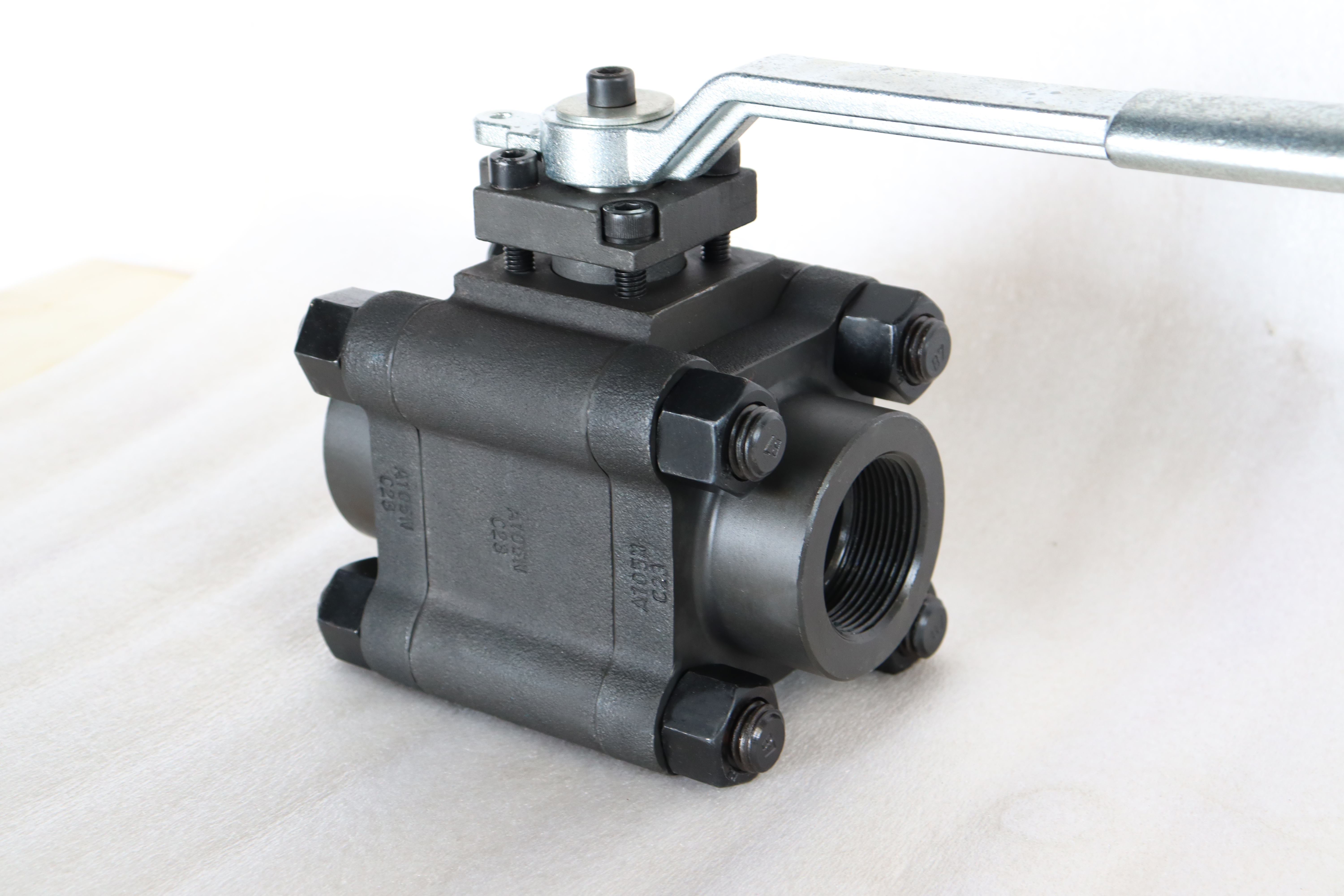
The 800 in this name is a real designation, but it is not a step in the table most people think it comes from. ASME B16.34 rates valves at 150, 300, 600, 900, 1500 and 2500, and 800 is not one of them. It is also not a flange class: ASME B16.5 has no Class 800, so there is no flange pattern to bolt this valve to if a flanged end is asked for. The number comes from the small forged valve family, where 800 sits between 600 and 900 and is used for gate, globe and check valves in bar stock and small forgings.
That borrowing is harmless until it reaches the end connection, and then it stops being harmless. A one inch valve at this pressure is normally threaded, socket welded or butt welded, and all three of those are defined by their own standards. So this page explains where 800 comes from, why a flange cannot be Class 800, and what to write on the order when the line needs a flange: a class and a flange table, chosen from the ones that exist.
Design and Construction
The valve is a small forged body with a floating ball, a stem through the top and a seat on each side. At one inch the ball is light enough that the line pressure seats it against the downstream ring without any trunnion, which is why the design is compact and why the operating torque stays within a short lever or a small handwheel. The body is machined from a forging rather than cast, because at this wall thickness a casting defect is a leak path rather than a margin.
The trim enters through the body joint, and on a valve this size the joint is small enough that the whole valve can be held in one hand while it is assembled. That is also the reason the seat is replaceable in a workshop rather than only in a factory: the body comes apart on a bench, and the two wear items, the seat and the stem packing, are both reachable without touching the pipe.
Because the ends are threaded or welded rather than flanged, the valve has no bolt circle to define it. Its pressure boundary ends at the thread or at the weld prep, and the joint that matters is the one the installer makes. That is a different kind of valve from a flanged one, and it is why the end connection is the first line on the order rather than the last.

Material Options
The body is A105N, a forged carbon steel in the normalized condition, which is the normal choice for water, oil, gas and hydraulic service where nothing attacks carbon steel. At one inch the forging is small enough that a heat can be traced to a single valve, and the certificate that comes with it names the heat that is stamped on the body. The N is a heat treatment condition rather than a strength grade, and it is read off the certificate and not off the name.
The ball is a stainless grade, CF8 or CF8M, with a nickel deposit as standard and an alloy overlay where the medium is abrasive. A carbon steel ball is possible but it is not the default here, because at this pressure the ball is the part that has to stay round and a deposit on carbon steel is a coating rather than a material. The stem is a 410 or 420 stainless, or a 316 grade where the medium asks for it.
The seat is reinforced PTFE as standard, with PEEK, nylon or a metal seat as the alternatives. At one inch the seat ring is small, which is what allows a soft seat to be used at this pressure at all, but the choice is still a temperature choice: the seat sets the ceiling, and a valve with the right body and the wrong seat is a valve that has to come out of the line.
| Component | Standard Material | Optional Upgrade | Service Notes |
|---|---|---|---|
| Body | forged carbon steel, A105N | other forging grades on request | normalized condition on the certificate |
| Ball | CF8 or CF8M stainless | nickel or alloy overlay | the sealing face is the deposit |
| Stem | 410 or 420 stainless | 316 grade | anti blowout shoulder |
| Seat ring | reinforced PTFE | PEEK, nylon or metal | sets the temperature ceiling |
| Body joint | one bolted joint with a gasket | gasket on the drawing | trim goes in through it |
| Packing | PTFE V rings | graphite | adjustable gland |
| End connection | NPT or BSP thread, socket weld, butt weld | flange only in a class that exists | no Class 800 flange |
| Operator | lever or handwheel | miniature pneumatic or electric | quarter turn |
Technical Specifications
The page prints the class twice in two different ways, as 800LB and as PN 135 in one place and PN 130 in another. Neither PN value is in the pressure code table of API 6D, which lists 20, 50, 64, 100, 150, 250 and 420, so both are conversions rather than designations. A buyer should treat the PN figure as informative and the class as the thing that is ordered, and should not put either conversion on a datasheet where a flange has to be matched to it.
The ends that exist for this valve are NPT or BSP threads to ASME B1.20.1, socket weld to ASME B16.11 and butt weld to ASME B16.25. Where a flanged end is required, the flange has to be a class that exists, which at this pressure means Class 600 or Class 900 to ASME B16.5, and the flange then decides the face to face length and the bolting rather than the valve body. Face to face for the threaded and welded versions is the manufacturer dimension on the drawing, because the valve is not covered by a flanged valve table.
The operator is a lever or a small handwheel as standard, with a miniature rack and pinion pneumatic actuator or a quarter turn electric actuator available where the valve sits in a panel or under a cover. Weight and length are quoted with the drawing for the end connection ordered, because a socket weld valve and a threaded valve of the same bore are not the same length and neither is covered by a flanged table. The lever swing also has to be checked against the pipe it sits next to.
| Item | Value |
|---|---|
| Nominal size | 1 inch (DN25) |
| Class designation | 800LB, a class from the small forged valve family |
| Rating named on the certificate | Class 600 or Class 900 to ASME B16.34, stated on the order |
| Pressure conversion printed on the page | PN 135 in one line and PN 130 in another, neither in API 6D |
| Body style | forged body, bolted joint |
| Ball support | floating |
| Bore | full bore at one inch |
| Body material | A105N forged carbon steel, normalized |
| Ball material | CF8 or CF8M stainless |
| Ball options | nickel deposit or alloy overlay |
| Stem material | 410 or 420 stainless, 316 on request |
| Seat material | reinforced PTFE |
| Seat options | PEEK, nylon or metal |
| Packing | PTFE V rings or graphite |
| End connection | NPT or BSP thread, socket weld, butt weld |
| Thread standard | ASME B1.20.1 |
| Socket weld standard | ASME B16.11 |
| Butt weld standard | ASME B16.25 |
| Flange, where fitted | ASME B16.5 Class 600 or 900, there is no Class 800 |
| Design standard | ASME B16.34 and API 608 |
| Test standard | API 598 shell and seat test |
| Test pressure | shell 1.5 times and seat 1.1 times the rating |
| Temperature range | minus 29 to plus 425 Celsius, metal temperature |
| Operation | lever or handwheel, actuator on request |
| Marking | size, class, body code, heat number |
| Weight and length | quoted with the drawing for the end connection ordered |
Standards and Compliance
ASME B16.34 is the document that actually rates the pressure boundary, and it does so at 600 or at 900, not at 800. It sets the minimum wall from the bore and the class, so a one inch valve certified at 900 carries a wall that looks heavy against its bore, which is what a photograph of this valve shows. API 608 adds the general ball valve requirements: marking, pressure test and the fire safe option. Where the valve is bought against a pipeline specification, API 6D applies and adds the cavity relief and the documentation package, though at one inch the buyer is more often a plant than a pipeline.
The 800 designation belongs to the small forged valve family, where it is a standard class for gate, globe and check valves. It is not a class that a ball valve is rated at in ASME B16.34, and it is not a flange class in ASME B16.5. That is not a reason to refuse the name, it is a reason to know what it means: it places the valve between 600 and 900 in the buyer vocabulary, and the certificate still has to name a rating the standards recognise.
On a class 800 forging the test is the same procedure at a rating that has no flange behind it: one and a half times for the shell, one and one tenth for the seat, held long enough to see a weep at a thread. Threaded and socket weld ends are where a small valve leaks, and neither is covered by a flange dimension, so the end preparation is checked against the standard rather than against a mating part. Fire safe, where asked for, is a separate type test to API 607, API 6FA or ISO 10497, and the three do not substitute for one another.
| Requirement | Standard | What J-VALVES Supplies |
|---|---|---|
| Pressure boundary | ASME B16.34 | rates at 600 or 900, not at 800 |
| General ball valve | API 608 | marking, pressure test, fire safe option |
| Threaded ends | ASME B1.20.1 | NPT taper thread |
| Socket weld ends | ASME B16.11 | socket depth and weld prep |
| Butt weld ends | ASME B16.25 | weld prep profile |
| Flange, where fitted | ASME B16.5 Class 600 or 900 | no Class 800 flange exists |
| Shell and seat test | API 598 | 1.5 times shell, 1.1 times seat |
| Fire test | API 607, 6FA or ISO 10497 | named on the order |
| Marking | API 608 | size, class, body code, heat number |
Manufacturing Process
The body starts as a forging, is normalized, and is then machined in one setup from the end that carries the joint. The bore is drilled and reamed, the seat pockets are cut square to the joint face, and the thread is cut and gauged rather than run on a die, because a tapered thread that is cut to depth by eye either leaks or splits the fitting it is screwed into.
The socket weld ends are bored to the ASME B16.11 depth and the butt weld ends are machined to the ASME B16.25 profile, and both are left with a weld prep that matches the wall of the pipe they will meet. Assembly sets the ball and the two seats, fits the stem with its thrust washer and packing, and closes the joint on a new gasket, after which the valve is stroked and the torque felt by hand.

Quality Control and Testing
The forging certificate is written against the heat number stamped on the body, and the ball and stem certificates follow the same pattern. Where the order asks for a positive material identification report, that report is issued against the same heat; it is not claimed here as a standing practice, because it is a line on the purchase order rather than a default. The thread is checked with a gauge rather than by fitting a coupling, since a coupling that has been used will accept a thread that is out of tolerance.
The shell test is run at one and a half times the rating of the class the valve is actually certified to, with the body joint and the packing watched. The seat test follows in both directions at one and one tenth times with the cavity open, and the acceptance on a soft seat is no visible leakage. The valve is then dried, the ends are capped, and the plate is read against the certificate before packing.
| Step | What Is Checked | Standard or Acceptance |
|---|---|---|
| Forging | heat number and certificate | read against the stamped code |
| Thread | checked with a gauge | not with a used coupling |
| Socket weld bore | depth to ASME B16.11 | checked before assembly |
| Butt weld prep | profile to ASME B16.25 | matched to the pipe wall |
| Seat pocket | square to the joint face | cut in the same setup |
| Shell test | wall, joint and packing at 1.5 times | API 598 duration |
| Seat test | both directions, cavity open | no visible leakage on a soft seat |
| Marking | plate against the certificate | class checked against the rating table |

Applications and Industry Service
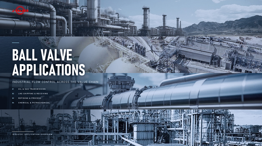
This valve is bought for instrument and sample lines, hydraulic power packs, small bore high pressure headers, chemical injection skids and test stands, where the pipe is one inch or smaller and the pressure is set by a process rather than by the line size. In those services the valve is chosen for its ends and its seat far more than for its body, because everything about the installation happens at the thread or the weld.
It is the wrong valve for a line that has to be isolated with a flange joint, for a line where a pig or a scraper passes, and for a service where the flow is large enough that a one inch bore is the restriction. It is also the wrong valve where the medium carries solids that would sit between the ball and the seat, because at this bore there is no room for a solids handling seat.
Installation, Operation and Maintenance
A threaded end is made up with a sealant that suits the medium, applied to the male thread and not to the valve body, and the valve is held on the body flats rather than on the lever while the joint is tightened. A socket weld end is welded with the valve fully open and the seat protected from heat, and the weld is cooled before the valve is stroked. Both are joints that are made once, and neither tolerates a valve that is used as a lever to pull a pipe into line.
In service the packing gland is the first item to need attention, and it can be adjusted without removing the valve. The seat is replaced on a bench: the body is opened, the ball and the two rings come out, and the joint is remade on a new gasket. Because the valve is small, the usual failure is not wear but contamination, so a strainer upstream is worth more than a spare seat ring.
How to Specify and Order
The order should carry size, the class the certificate will name, the end connection and its standard, the body material, the ball and seat materials, the operator and the test standard. Write the end connection first: NPT, BSPT, socket weld or butt weld, with the standard number beside it, because that single line decides the length, the weight and the joint the installer has to make.
Where the line needs a flange, do not write Class 800. Write Class 600 or Class 900 to ASME B16.5 and let the flange set the joint, or write a PN class if the line is European. Where the enquiry carries 800, say which rating the certificate should name, because the shop cannot certify to a class that the rating table does not contain, and the difference will otherwise be discovered at the witness test.
FAQ
Q: Is Class 800 a real pressure class?
A: It is real in the small forged valve family, where 800 is a standard class for gate, globe and check valves. It is not one of the classes in the ASME B16.34 rating table, which runs 150, 300, 600, 900, 1500 and 2500, and it is not a flange class in ASME B16.5. So the name is a useful shorthand for a high pressure small valve, and the certificate still has to name a rating from a table.
Q: Can this valve be supplied with flanges?
A: Not with Class 800 flanges, because they do not exist. If the line needs a flanged joint, the valve is ordered with Class 600 or Class 900 flanges to ASME B16.5, or with a PN flange to EN 1092-1, and the flange then sets the face to face length and the bolting. The alternative is to keep the valve threaded or welded and put the flange on the pipe, which is often the cheaper answer at one inch.
Q: Why does the page give two different PN numbers?
A: Because both are conversions rather than designations. PN 135 and PN 130 appear in different places on the original page, and neither is in the pressure code table of API 6D, which lists 20, 50, 64, 100, 150, 250 and 420. A conversion is only useful for a rough comparison; the figure that goes on a datasheet or a flange inquiry has to be a class that a table recognises.
Q: Which end connection should be ordered?
A: It depends on how the joint will be made and how often it will be broken. A thread is the quickest joint and the easiest to remake, and it is the right choice for instrument and sample lines. A socket weld is stronger and better in vibration, at the cost of being a permanent joint. A butt weld gives the best joint of the three and the cleanest bore, and it is the choice for a line that will be radiographed.
Q: Is a soft seat usable at this pressure?
A: At one inch, yes, because the seat ring is small and the force on it is the pressure times a small area. The limit is temperature rather than pressure, and the seat table steps up through reinforced PTFE, PEEK and metal for that reason. The design temperature should be stated on the enquiry so that the seat is chosen against it rather than against the pressure alone.
Q: What should the nameplate carry?
A: Size, the class the valve is certified to, the body material and the heat number. Where the order was written as 800, the plate should still carry the rating from the table that the certificate names, because a plate that carries a class the standard does not contain cannot be checked by the buyer or by an inspector. The heat number is what ties the plate to the certificate.


Hot Products


News
Ball Valves On A Bottom Loading Gantry: Creep, Dry Break And The Test That Proves Neither
A loading gantry cycles a ball valve far more than it is designed for and still cannot prove shut-off. Where creep starts, and what to specify.
Read More
Lined Ball Valves in Acid Service: The Liner Does Not Fail, The Steel Behind It Does
The valve came out of the line looking better than most valves that come out of a hydrochloric acid line. Three inch, PFA lined, cast body, Class 150, fourteen months in service on a 32 percent acid transfer duty at 55 to 60 degrees C, about forty open and close cycles a week. The paint was intact.
Read More
Ball Valves in Amine CO2 Capture: Heat Stable Salts, Rich Amine, And The Three Places The Body Thins
Rich amine at 110 C with heat stable salts is where capture plant ball valves fail. Materials, velocity limits, cavity gas and seat choice, with numbers.
Read More
Fail-Safe Ball Valve Actuators: Spring Return, Stored Air, And The Torque Nobody Checks
Spring return or stored air? The answer is a torque curve, not a datasheet box. Sizing, receiver volume, closing time and four silent failures.
Read More