


CHINA J-VALVES Offers Various High-quality I ndustrial Ball Valves
J-VALVES, a distinguished professional ball valve manufacturer rooted in China, takes pride in its extensive product portfolio. Our offerings span a wide range, including trunnion-mounted ball valves, floating ball valves, high-temperature ball valves, high-pressure ball valves, metal-sealed ball valves, ultra-low temperature ball valves, DBB ball valves, Three-way And Four-way Ball Valve, and fully welded ball valves. Each product is a testament to our commitment to precision engineering and reliable performance. Meticulously crafted, they are designed to not only meet but exceed the most stringent industrial demands, ensuring stable operation even under extreme conditions. This enables us to provide our clients with high-value services and makes our valves widely sought-after in industries.
Product Category
Contact Us


-
J-VALVES-Q41F
-
J-VALVES
Overview of the J-VALVES 3 Inch 600LB WCB Two Piece Floating Ball Valve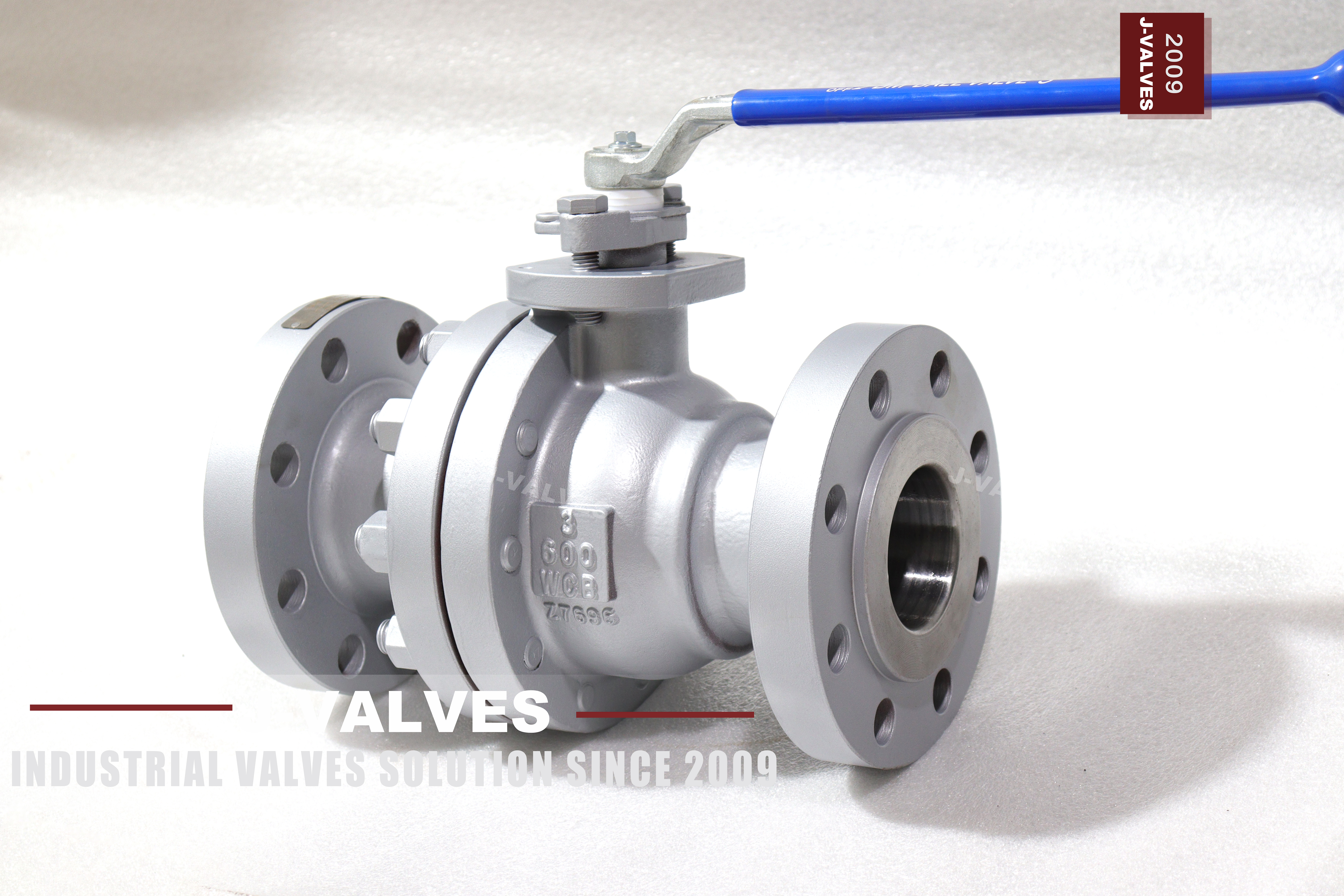
A floating ball has no trunnions, so nothing holds it in the middle of the body. Line pressure pushes it downstream into the seat on that side, and the contact between ball and seat is what seals. That is elegant, it needs no extra parts, and it works for as long as the pressure keeps pushing the same way. It also means the seal is not a mechanical arrangement at all, it is a balance of forces that a change in pressure can undo.
At three inch and Class 600 that balance is worth thinking about, because this is about the last size where the valve is operated by hand and the pressure is high enough for the forces to be large. A pump stopping, a branch reversing, or a column of liquid stopping too fast will all reverse or unload the pressure across the ball for a moment. In that moment the ball can leave its seat, and what it does next is the subject of this page.
Design and Construction
Two pieces with one bolted joint, and the joint sits between the ball and the pipe on one side, which is why the trim comes out that way. The ball has clearance to move along the axis between the two seats, and that clearance is what makes the design work: pressure pushes the ball until it touches one seat, and the upstream seat is then not in contact at all. Only one seat seals at a time, in the direction the pressure is pushing.
That is also the weakness. The movement that lets the ball find its seat is the same movement that lets it leave, and the distance it can travel is the clearance between the seats. A ball that is pushed off its seat and returns travels that distance and arrives with whatever energy the pressure difference gave it, and the thing it arrives against is a polymer seat ring inside a two piece body.

Material Options
The body code is WCB, a cast carbon steel, which is the normal body for a three inch Class 600 valve and needs no argument. The seat is PTFE as standard with reinforced PTFE or PPL listed for temperature, and a metal seat on request. On a valve that sees pressure reversals, the seat material matters more than usual, because a seat that has taken a compression set from an impact is a seat that no longer seals in the direction that matters.
The ball and the stem follow the body code unless the order says otherwise. Where the medium is corrosive the body code changes and the whole valve is ordered against it, and where the service is cold enough for a low temperature steel the code changes to a forging suited to that. Neither change affects the mechanism described here, which is a property of the floating design rather than of the alloy.
| Component | Standard Material | Optional Upgrade | Service Notes |
|---|---|---|---|
| Body | WCB cast carbon steel, code as stamped | other casting codes on order | two sections, one bolted joint |
| Ball | carbon steel with hard facing | stainless on order | floats between the two seats |
| Stem | 17-4PH or equivalent | named on the order | retained by the body cover |
| Seat ring | PTFE | reinforced PTFE, PPL or metal | takes the impact after a reversal |
| Sealing direction | one seat at a time, whichever the pressure pushes | not a double block design | the mechanism this page is about |
| Body joint | one gasketed studded joint | not offered as a welded body | new gasket at every break |
| End facing | raised face to ASME B16.5 | ring joint on order | chosen at order |
| Operator | lever | actuator on request, closing time specified | closure speed is a hydraulic decision |
Technical Specifications
Three numbers are settled before anything else is discussed: the size, the class and the bore. The flange is an ASME B16.5 Class 600 raised face pattern in three inch, the bore through the ball is full, and the face to face is taken from ASME B16.10 for a flanged valve of this size and class. The built length is on the signed drawing rather than here. Class 600 is PN 100 in the API 6D code. None of those three numbers says anything about what happens when the flow reverses, which is the subject of this page and the reason a floating ball behaves differently from a trunnion one.
The number that matters for this page is not on the data sheet at all: it is the closing time. A hand lever closes this valve over a second or two, which is slow enough that the pressure wave has somewhere to go. An actuator that closes it in a fraction of a second is a different hydraulic event entirely, and the valve that was fine on a lever is not automatically fine on a fast actuator.
| Item | Value |
|---|---|
| Nominal size | 3 inch (DN80) |
| Pressure class | Class 600 (PN 100, the API 6D pressure code) |
| Body style | two piece, one gasketed body joint |
| Ball support | floating, no trunnion |
| Sealing principle | line pressure pushes the ball into the downstream seat |
| Bore | full bore |
| Body material | WCB cast carbon steel, code as stamped |
| Ball material | carbon steel with hard facing |
| Stem material | 17-4PH or equivalent, stated on the order |
| Seat material | PTFE as standard |
| Seat options | reinforced PTFE, PPL or metal seat |
| End connection | raised face flange, ASME B16.5 Class 600 |
| Face to face | dimension on the signed GA drawing, held to ASME B16.10 |
| Design standard | ASME B16.34 and API 608 |
| Test standard | API 598 shell and seat test |
| Test pressure | shell 1.5 times and seat 1.1 times the class rating |
| Temperature range | minus 29 to plus 425 Celsius, metal temperature |
| Temperature ceiling | set by the seat material, not by the body code |
| Transient behaviour | ball can lift off the seat when the pressure reverses |
| Closure speed | a hand lever closes slowly, a fast actuator does not |
| Operation | lever, actuator with closing time stated on request |
| Marking | size, class, body code, heat number |
| Documentation | EN 10204 3.1 on request |
| Weight | quoted with the drawing for the size and trim ordered |
Standards and Compliance
ASME B16.34 supplies the wall and the rating; API 608 is the quarter turn product standard that governs a three inch Class 600 floating valve, with API 598 for the shell and seat acceptance figures. None of the three says anything about what happens when the pressure reverses, because a valve standard describes a valve in a steady state rather than a valve in a transient.
That gap is why the transient belongs in the system design rather than in the valve specification. Water hammer is a piping phenomenon: it comes from a column of liquid being stopped, and the valve is only the thing that stopped it. The answer is usually a change in the system, such as a slower closure, a bypass, or a different valve position, rather than a different valve.
| Requirement | Standard | What J-VALVES Supplies |
|---|---|---|
| Pressure boundary | ASME B16.34 | minimum wall and the Class 600 rating at temperature |
| Quarter turn product | API 608 | the governing product standard at this size and class |
| Shell and seat test | API 598 | 1.5 times the rating for the shell, 1.1 times for the seat |
| Flange pattern | ASME B16.5 Class 600 | three inch, raised face |
| Face to face | ASME B16.10 | flanged valve length for the size and class |
| Pressure code | API 6D clause 7.2 | Class 600 is written PN 100 |
| Surge and water hammer | piping design, not a valve standard | the gap this page exists to fill |
| Marking | API 608 and the order | size, class, body code, heat number |
| Documentation | EN 10204 3.1 | issued against the heat number on request |
Manufacturing Process
The body is cast, inspected and machined, with the joint face and the seat pockets cut from one datum so that the two seats are coaxial. That coaxiality is what the floating ball relies on: the ball finds whichever seat the pressure pushes it against, and if the two pockets are not in line the ball has to tilt to reach the second one, which puts an edge load on the ring instead of a face load.
Assembly is the ball and the upstream seat into the body, the downstream seat into the end cap, and the cap closed over a new gasket with the studs brought down in a cross pattern. The valve is then cycled, which beds the ball against both seats in turn, and only after that is it tested. A valve tested before cycling reads high on torque and can read well on leakage, which is the wrong combination.

Quality Control and Testing
The shell test is at one and a half times the rating and the seat test at one and one tenth times, in both directions, with the cavity open. On a floating ball the two directions test two different seats, and a valve that passes one and weeps on the other has a pocket that is out of line rather than a damaged ring. Both directions are recorded rather than summarised.
The test cannot reproduce a surge, and no standard asks it to. What the test can do is establish that both seats seal statically, which is the baseline the transient is measured against. On a valve that is going onto a line with a known surge problem, the useful additional record is the operating torque after cycling, because a seat that has been impacted reads higher the next time the valve is closed.
| Step | What Is Checked | Standard or Acceptance |
|---|---|---|
| Casting | wall and surface before machining | found before the machining time is spent |
| Seat pockets | coaxial, cut from one datum | a tilt puts an edge load on the ring |
| Seat insert | thickness, fit, no damage | checked before assembly |
| Body joint | gasket batch, stud torque | cross pattern to the drawing |
| Shell test | wall and the joint | API 598 at 1.5 times the rating |
| Seat test | both directions recorded separately | one seat per direction on a floating ball |
| Cycle and torque | operating torque after bedding | the figure a surge will move |

Applications and Industry Service
This valve is for three inch lines at Class 600 where the duty is isolation: process branches, utility headers, and the isolation points around equipment. It is operated by hand, it stays at one end of its travel, and in that service the floating design is entirely adequate and cheaper than a trunnion valve of the same size, with fewer parts to wear and a lighter lever.
It becomes the wrong choice in three situations. On a pump discharge where the pump stops without a check valve, the reversal is regular rather than exceptional and a trunnion valve removes the mechanism. On a line where the valve is closed by a fast actuator, the closure itself generates the transient. And on a line with a long column of liquid and a high velocity, the surge energy is large enough that the seat is not the part to be relying on.

Installation, Operation and Maintenance
The valve position matters. Installed with the seat that seals in the direction of normal flow on the downstream side, the ball sits against that seat while the line is running, and the return travel after a reversal is short. Installed the other way round it still seals, because a floating ball seals both ways, but the ball has further to travel each time the pressure changes sides, and the impact is correspondingly larger.
Where the line has a surge problem, the fix is upstream of the valve: close it slowly, leave a bypass open until the flow has stopped, or fit a check valve so the column is stopped somewhere other than at the ball. When a valve on such a line is opened for maintenance, the seat rings are inspected as a pair and the ball is checked for a flat where it has been hammering, because a flattened ball will hold a rate and lose it again.
How to Specify and Order
The order line needs size, class, body style, body code, bore, seat material, end facing, operator and test standard. Where the valve will be actuated, the closing time belongs on the order as well, because it is the difference between a valve that closes and a valve that generates a pressure wave. That item is almost never written and almost always matters on a line that has had a surge event.
The documents to read before acceptance are the plate, the certificate and the drawing. The plate carries size, class, code and heat number; the certificate says what that heat was; the drawing carries the face to face, the flange pattern and the joint torque. On a valve that is going to see pressure reversals, the drawing is also where the seat material should be recorded, because that is the part the transient will damage first.
FAQ
Q: How does a floating ball seal if nothing holds it in place?
A: Line pressure holds it. The ball sits between two seats with clearance to move along the axis, and pressure pushes it into the seat on the downstream side, so the contact between ball and ring is what seals. That means only one seat is in contact at a time, and the seal exists only while the pressure keeps pushing in the same direction.
Q: What happens when the pressure reverses?
A: The ball lifts off the seat it was resting on and travels across the clearance to the other seat, which is the seat on the other side. It arrives with the energy the pressure difference gave it, and it lands on a polymer ring inside a two piece body. Repeated reversals work the ring and can mark the ball, which is why a valve on a line with regular reversals is better served by a trunnion design.
Q: Is a hand lever better than an actuator for this valve?
A: Not better in general, but safer on a line with a surge risk, because a hand closes the valve over a second or two and gives the pressure wave somewhere to go. An actuator that closes in a fraction of a second is a different hydraulic event, and if it is chosen the closing time belongs on the order along with the valve.
Q: Which way round should the valve be installed?
A: Either way seals, because a floating ball seals in both directions, but the travel after a reversal is shorter if the ball is already resting against the seat that faces the normal flow direction. On a line with a known surge problem, that orientation reduces the distance the ball has to travel and therefore the impact when it gets there.
Q: How do I fix a water hammer problem?
A: In the system, not in the valve. Close the valve more slowly, keep a bypass open until the flow has stopped, or fit a check valve so the column of liquid is stopped somewhere other than at the ball. Changing to a trunnion valve removes the floating mechanism from the equation but does not remove the pressure wave, which will find the next weakest thing in the line.
Q: Does the shell test prove the valve will survive a surge?
A: No. The shell test is a static proof at one and a half times the rating, and a surge is a transient that can exceed the static pressure for a moment and then reverse. What the test establishes is that both seats seal statically, which is the baseline. Surviving the transient is a matter of the system and of how the valve is operated.


Hot Products


News
Ball Valves in Amine CO2 Capture: Heat Stable Salts, Rich Amine, And The Three Places The Body Thins
Rich amine at 110 C with heat stable salts is where capture plant ball valves fail. Materials, velocity limits, cavity gas and seat choice, with numbers.
Read More
Fail-Safe Ball Valve Actuators: Spring Return, Stored Air, And The Torque Nobody Checks
Spring return or stored air? The answer is a torque curve, not a datasheet box. Sizing, receiver volume, closing time and four silent failures.
Read More
Ball Valve Stem Leak: The Gland, The Backseat And The Repair That Cannot Be Done Live
A stem leak on a quarter turn valve is four different failures. What gland tightening buys you, why the backseat is usually absent, and what needs a shutdown.
Read More
Ball Valves in A Kraft Pulp Mill: Black Liquor, Green Liquor And The Cost of Choosing The Alloy by Habit
White liquor at pH 14 cracks carbon steel welds, black liquor sets solid below 100 C, green liquor dregs grind seats: alloy choice and torque in a kraft mill.
Read More