


CHINA J-VALVES Offers Various High-quality I ndustrial Ball Valves
J-VALVES, a distinguished professional ball valve manufacturer rooted in China, takes pride in its extensive product portfolio. Our offerings span a wide range, including trunnion-mounted ball valves, floating ball valves, high-temperature ball valves, high-pressure ball valves, metal-sealed ball valves, ultra-low temperature ball valves, DBB ball valves, Three-way And Four-way Ball Valve, and fully welded ball valves. Each product is a testament to our commitment to precision engineering and reliable performance. Meticulously crafted, they are designed to not only meet but exceed the most stringent industrial demands, ensuring stable operation even under extreme conditions. This enables us to provide our clients with high-value services and makes our valves widely sought-after in industries.
Product Category
Contact Us


-
J-VALVES-Q41F
-
J-VALVES
Overview of the J-VALVES 1x0.75 Inch 150LB A105N Two Piece Floating Ball Valve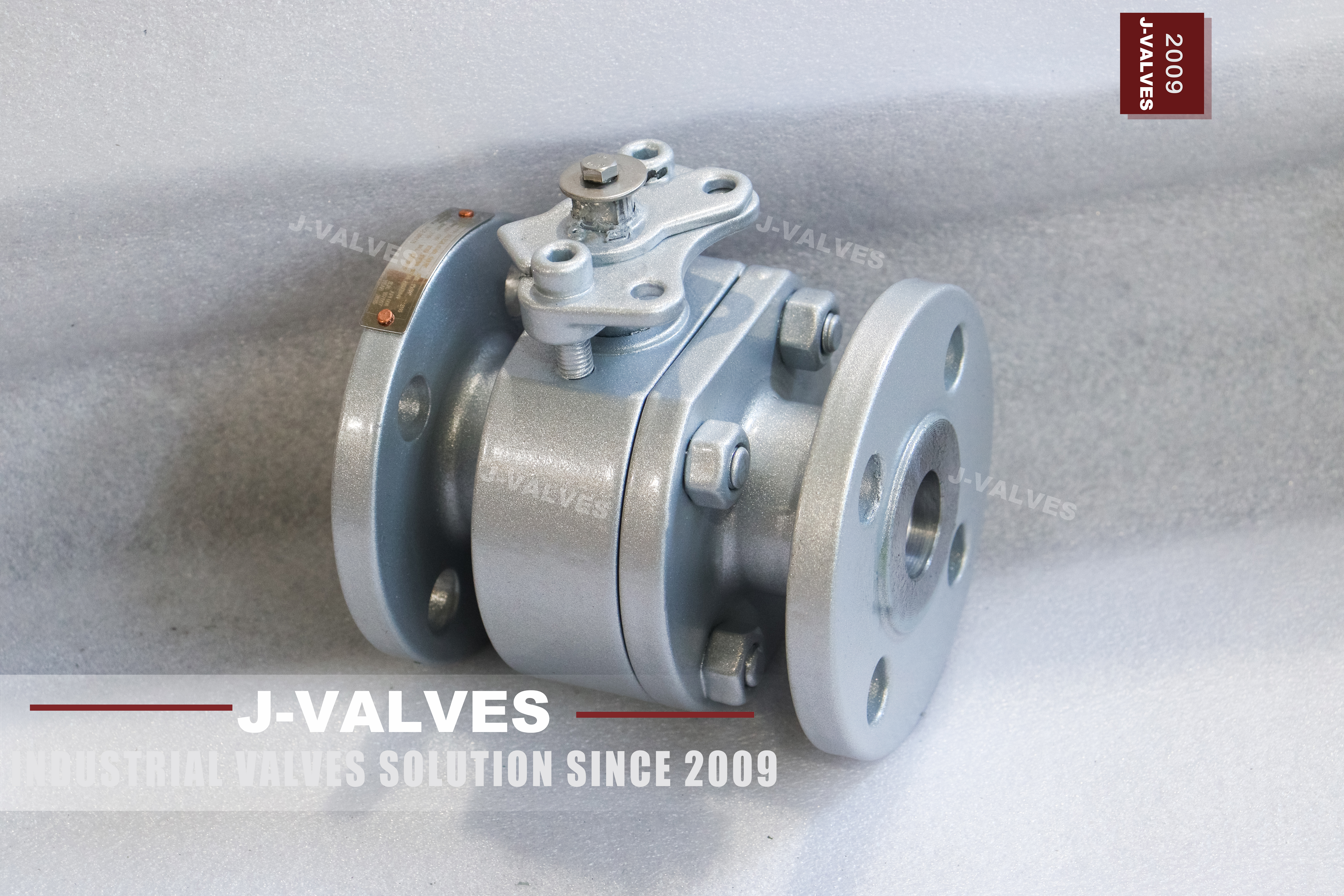
At one inch and Class 150 the pressure is the least interesting thing about this valve. Any soft seated ball valve of this size holds the class rating without argument, which is why the enquiry rarely starts with pressure and almost always ends with temperature. The parts that decide what the valve can take are the seat and the packing, and of the two the seat is the one that gets chosen at the quotation stage and then forgotten until the valve starts weeping.
The source page lists three seat materials: PTFE, reinforced PTFE, and PPL, with a metal seat available on request. Those three are not grades of the same thing. They sit at different temperature ceilings, and the ceiling of the fitted seat is the ceiling of the valve, whatever the body code and the class number say on the plate. That is the decision this page is about, and it is worth more attention than the third decimal of a pressure rating.
Design and Construction
The ball floats. It is not carried on trunnions, so line pressure pushes it downstream into the seat that faces the low pressure side, and that is the seat that does the sealing. At DN20 the area is small enough that the load on the seat never becomes a problem for the operator, which is why a trunnion would be extra parts with nothing to do. The same valve at six inch would need trunnions, and that is a different product rather than a bigger version of this one.
The body is in two pieces with one bolted joint, and the joint is where the ball and the seats come out. On a valve this small the body is forged rather than cast, because a forged section has no porosity to find at the seat pocket and the wall is thin enough that a casting defect would matter. The lever is mounted on a stem that is retained by the body cover, so the packing can be reached from the top without opening the pressure boundary.
Material Options
The body code is A105N, and the N is the part buyers ask about. It stands for normalized: the forging is heat treated to refine the grain before machining, and the source page states it. What that buys is a tougher, more uniform section and a heat treatment record that travels with the certificate. What it does not buy is a higher pressure class, a higher temperature ceiling, or corrosion resistance. At Class 150 none of those follow from the heat treatment, and a buyer who expects them has bought the wrong letter.
The seat goes the other way. PTFE is the standard, reinforced PTFE is the next step, and PPL is the option listed above it, with a metal seat on request for duty the elastomer cannot take. Each step moves the temperature ceiling and none of them moves the pressure rating, because at this class the pressure was never the constraint. The ball is A105N with hard chrome or stainless on request, and the stem is stainless, which is the only part of the trim that sees the weather.
| Component | Standard Material | Optional Upgrade | Service Notes |
|---|---|---|---|
| Body | A105N forged carbon steel, normalized | not offered in another alloy | one bolted body joint |
| Ball | A105N with hard chrome | 316 stainless | floats into the downstream seat |
| Stem | 316 stainless | A105N with surface treatment | retained by the body cover |
| Seat ring | PTFE | reinforced PTFE or PPL | sets the temperature ceiling |
| Seat facing | soft insert, replaceable | metal seat on request | the wear part in dirty service |
| Body joint | one gasketed studded joint | not offered as a welded body | new gasket at every break |
| Operator | lever | worm gear, pneumatic, electric | pad height not stated on the page |
| Surface | as machined, coating not stated | to be named on the order | outdoor duty needs it specified |
Technical Specifications
Face to face follows ASME B16.10 for a flanged valve of this size and class, and the flange is an ASME B16.5 Class 150 raised face pattern. Neither is printed here as a number, because those numbers belong to the tables and quoting one from a page would make it look measured. The size data sheet gives the DN20 bore and the DN25 flange; the assembled length, the lever envelope and the weight of a particular build are dimensioned on the signed general arrangement drawing.
Class 150 is PN 20 in the API 6D pressure code, and the rating is not one number even at this class: it falls with temperature, and the table that governs the fall is in ASME B16.34. On a small valve that matters less than the seat ceiling does, but it still decides what the shell test is done at. API 598 sets the shell test at one and a half times the rating and the seat test at one and one tenth times, so both follow the reduced rating rather than the class label.
| Item | Value |
|---|---|
| Nominal size | 1x0.75 inch (DN25 x DN20) |
| Pressure class | Class 150 (PN 20, the API 6D pressure code) |
| Body style | two piece, one gasketed body joint |
| Ball support | floating, no trunnion |
| Bore | reduced bore, DN20 through the ball |
| Body material | A105N forged carbon steel, normalized, code as stamped |
| Ball material | A105N with hard chrome, 316 optional |
| Stem material | 316 stainless, or A105N with surface treatment |
| Seat material | PTFE as standard |
| Seat options | reinforced PTFE or PPL, metal seat on request |
| End connection | raised face flange, ASME B16.5 Class 150 |
| Face to face | dimension on the signed GA drawing, held to ASME B16.10 |
| Design standard | ASME B16.34 and API 608 |
| Test standard | API 598 shell and seat test |
| Test pressure | shell 1.5 times and seat 1.1 times the class rating |
| Temperature range | minus 29 to plus 425 Celsius, metal temperature |
| Temperature ceiling | set by the seat material, not by the body code |
| Fire test | API 607 as stated on the source page |
| Anti static device | described as standard on the source page |
| Anti blow out stem | described as standard on the source page |
| Operation | lever, worm gear or actuator on request |
| Marking | size, class, body code, heat number |
| Documentation | EN 10204 3.1 on request |
| Weight | quoted with the drawing for the size and trim ordered |
Standards and Compliance
ASME B16.34 fixes the minimum wall and publishes the pressure temperature rating for the material group. API 608 is the quarter turn product standard and is the document that governs a valve of this type, which is worth saying plainly: API 6D is written for pipeline valves and is not the governing document at one inch and Class 150, even though the same shop builds both. API 598 supplies the acceptance figures for the shell and seat tests that both documents point at.
The page also claims a fire safe design to API 607, and that claim needs to be read precisely. Fire safety is a type test on a design rather than a test on each valve, and the three documents in circulation are not interchangeable: API 607 covers soft seated quarter turn valves, API 6FA is written for pipeline valves to API 6D, and ISO 10497 is a method. A certificate to the wrong one is refused at the gate, so the standard belongs on the order by name.
| Requirement | Standard | What J-VALVES Supplies |
|---|---|---|
| Pressure boundary | ASME B16.34 | minimum wall and the rating for the alloy group at Class 150 |
| Quarter turn product | API 608 | the governing product standard at this size and class |
| Shell and seat test | API 598 | 1.5 times the rating for the shell, 1.1 times for the seat |
| Flange pattern | ASME B16.5 Class 150 | raised face, DN25 |
| Face to face | ASME B16.10 | flanged valve length for the size and class |
| Fire test | API 607 | type test on the design, certificate on request |
| Pipeline document | API 6D | applies to pipeline valves, not the governing document here |
| Marking | API 608 and the order | size, class, body code, heat number |
| Documentation | EN 10204 3.1 | issued against the heat number on request |
Manufacturing Process
The body starts as a forging, is normalized, and is then machined in two halves. The joint face and the seat pocket are cut in the same setup so the pocket stays square to the face, and the flange face is machined last so that any distortion from the earlier operations is taken out at the end rather than built in at the start. On a DN25 body there is very little material to hide an error in, which is why the sequence is fixed rather than left to the operator.
Assembly is short. The ball goes into one half, the seats follow, the second half is closed over a new gasket, and the studs are brought down in a cross pattern until the faces are parallel. The stem and the lever go on, the valve is cycled a few times to settle the seats, and then it is tested. The order of those last two steps matters: a valve that is tested before it is cycled can pass and then weep after the first operation in the field.

Quality Control and Testing
The shell test proves the body and the joint at one and a half times the rating. The seat test is the one that earns its keep on a valve this size, because the insert is a small ring and a nick in it shows as a weep rather than a failure. Both directions are tested at one and one tenth times the rating, with the cavity open, and the acceptance is no visible leakage rather than a number on a gauge. That is the figure API 598 sets, and it is the figure the test sheet should quote.
Records are three documents read against each other. The nameplate states size, class, body code and heat number. The mill certificate behind the 3.1 documentation states what that heat was, including the normalizing treatment that the N on the plate promises. The test sheet states what the valve did under pressure. Positive material identification is written on the order rather than assumed, and on a small valve it is usually the cheapest way to settle a dispute five years later.
| Step | What Is Checked | Standard or Acceptance |
|---|---|---|
| Incoming forgings | code, heat number, normalizing record | certificate against the stamped code |
| Body machining | joint face, seat pocket, flange face | in process gauging against the drawing |
| Seat insert | thickness, fit in the ring, no damage | checked before assembly |
| Body joint | gasket batch, stud torque | cross pattern to the drawing value |
| Shell test | no leakage through any pressure boundary | API 598 at 1.5 times the rating |
| Seat test | no visible leakage, both directions | API 598 at 1.1 times the rating |
| Lever and marking | travel, stop position, plate data | checked before packing |

Applications and Industry Service
This is a utility valve. It belongs on instrument air, small water and steam branches, dosing skids, sample lines, and the isolation points around a skid where the pipe is one inch and the medium is clean. In those places it is opened and closed by hand, it sits at one end of its travel for months, and the thing that eventually stops it working is a seat that has taken a set or a gland that has dried out, not a loss of pressure containment.
It is the wrong valve in three situations. A medium that attacks carbon steel will attack the body long before the seat gives trouble, so a stainless body is the answer rather than a better seat. A line that has to be pigged needs full bore, and this valve is reduced bore by definition. And a service that cycles every few minutes will wear the insert and the packing on a schedule set by cycles, which is a maintenance plan rather than a valve choice.

Installation, Operation and Maintenance
Install with the lever clear of the pipe and the flange bolts reachable, and bring the mating flanges parallel before the studs are tightened, because a small raised face flange will not pull itself square and a cocked gasket leaks at the bottom of the ring where nobody looks. Leave the stem vertical or horizontal rather than inverted, so the packing stays wet and the cavity can drain. On a painted body the coating belongs on the drawing, since the page does not state one.
Maintenance is two jobs. The packing can be renewed from the top with the line live, because the stem is retained by the body cover. The seat insert needs the body joint open, which means a new gasket, clean faces and the torque pattern from the drawing. When a valve of this size starts weeping, the order of inspection is the insert first, the ball second and the joint third, because that is the order in which they usually fail.
How to Specify and Order
The order line needs size, class, body code with the N if normalized is wanted, bore, seat material, end facing, operator and test standard. Two of those get left out more than the rest: the seat material is written as PTFE when the duty needs reinforced PTFE or PPL, and the fire standard is named as fire safe without saying 607, 6FA or ISO 10497. Both are quiet omissions that only surface when the valve is in the line and the medium is hotter than expected.
Three documents should be read against each other before acceptance: the nameplate, the mill certificate and the drawing. The plate carries the code with the N, the certificate carries the normalizing record behind it, and the drawing carries the face to face, the flange pattern and the joint torque. On a valve this small the three fit on one page, which is the best argument for checking them rather than filing them.
FAQ
Q: What does the N in A105N mean?
A: It means normalized. The forging is heat treated to refine the grain before machining, and the source page states it. What that gives is a more uniform, tougher section and a heat treatment record behind the certificate. It does not raise the pressure class, it does not raise the temperature ceiling, and it does not make the body corrosion resistant, so it is not a substitute for choosing the right alloy.
Q: Does the seat material really change the temperature limit?
A: Yes, and at Class 150 it is the only thing that does. The body and the class stay the same whatever the medium temperature is, while the seat sits at its own ceiling. PTFE is the standard, reinforced PTFE sits above it, PPL is the listed option above that, and a metal seat is offered for duty the elastomer cannot take. The ceiling of the fitted seat is the ceiling of the valve.
Q: Should I order PPL or reinforced PTFE?
A: Order PPL when the medium runs hot enough that plain PTFE is marginal, and reinforced PTFE when the medium is at a moderate temperature but carries fines or cycles often. They are not interchangeable in price or in behaviour, and the order should name which one is wanted rather than leaving the default to the shop. Neither changes the pressure rating, because at this class pressure is not the constraint.
Q: Is this valve fire safe to API 607?
A: The source page states a fire safe design to API 607, and that is the right document for a soft seated quarter turn valve like this one. It is a type test on the design rather than a test on each valve, and API 6FA and ISO 10497 are different documents that cover different valve types, so the standard required by the project has to be written on the order by name.
Q: Why is the bore smaller than the pipe?
A: The valve takes a one inch flange and the passage through the ball is three quarter inch, so the bore is DN20 in a DN25 body. That is a reduced bore valve, and it costs less and turns more easily than a full bore one of the same size. The trade is a pressure drop across the valve and no passage for a pig, both of which matter on small lines more than buyers expect.
Q: What is the difference between this valve and a three piece of the same size?
A: A two piece body has one joint and the trim comes out towards the pipe; a three piece body lifts its middle section out, so the seat can be changed without disturbing either pipe connection. At one inch the two piece is normally enough, because the whole valve can be unbolted and swapped. The three piece earns its price where the trim is changed often or the pipe cannot be spread.


Hot Products


News
Ball Valves in A Kraft Pulp Mill: Black Liquor, Green Liquor And The Cost of Choosing The Alloy by Habit
White liquor at pH 14 cracks carbon steel welds, black liquor sets solid below 100 C, green liquor dregs grind seats: alloy choice and torque in a kraft mill.
Read More
Slug Flow And Ball Valves: What Actually Arrives At The Seat
A slug is liquid mass with momentum, not a pressure spike. What changes at the seat, in the cavity and at the actuator when liquid reaches a ball valve.
Read More
Ball Valves in Direct Lithium Extraction: PH 1 Eluate, Gypsum Scale And 438,000 Cycles in Twenty-Five Years
Direct lithium extraction swings valves from pH 1 eluate to pH 12 caustic, 48 column switches a day and gypsum scale. Materials, seats and torque.
Read More
Ball Valves in Geothermal Brine: Silica Scale, Chloride Cracking And The Cooling Trap
Why geothermal brine destroys ball valves: retrograde silica scale, calcite at the flash point, chloride cracking above 60 C and the 250 C seat limit.
Read More