


CHINA J-VALVES Offers Various High-quality I ndustrial Ball Valves
J-VALVES, a distinguished professional ball valve manufacturer rooted in China, takes pride in its extensive product portfolio. Our offerings span a wide range, including trunnion-mounted ball valves, floating ball valves, high-temperature ball valves, high-pressure ball valves, metal-sealed ball valves, ultra-low temperature ball valves, DBB ball valves, Three-way And Four-way Ball Valve, and fully welded ball valves. Each product is a testament to our commitment to precision engineering and reliable performance. Meticulously crafted, they are designed to not only meet but exceed the most stringent industrial demands, ensuring stable operation even under extreme conditions. This enables us to provide our clients with high-value services and makes our valves widely sought-after in industries.
Product Category
Contact Us


-
J-VALVES-Q41F
-
J-VALVES
Overview of the J-VALVES DN50x40 150LB A105 Two Piece Extended Stem Floating Ball Valve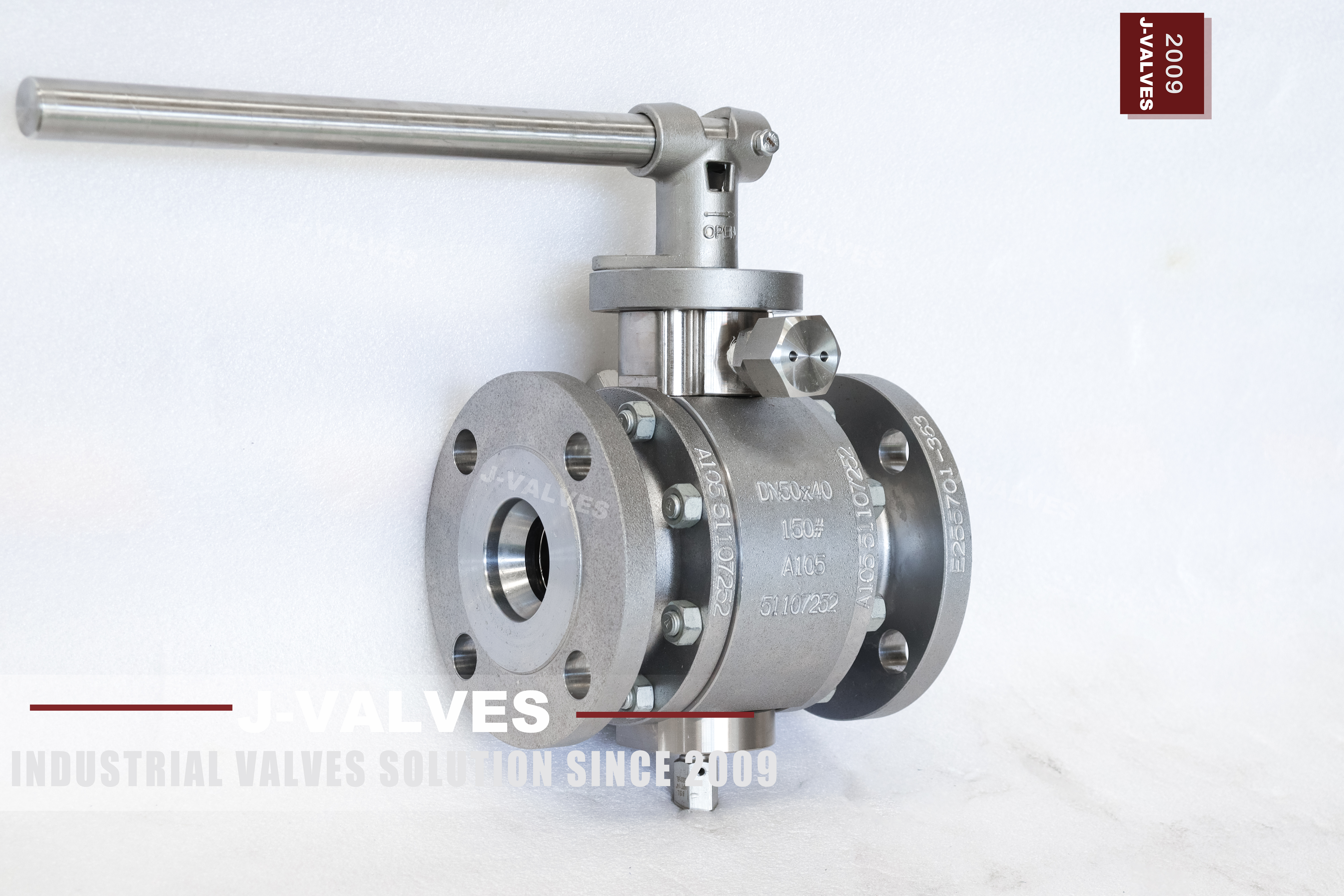
An extended stem valve is two assemblies in one purchase. Below the grade line there is a pressure vessel with a ball, two seats and one bolted joint, and everything written about buried valves applies to it: coating, cathodic protection, joint condition. Above the grade line there is a shaft in a tube with a lever on top, and none of that is a pressure part. It is a mechanism, and mechanisms fail differently from pressure vessels.
The mechanism is what this page is about. A stem that is bent by a foot, a wheelbarrow or a dropped tool still turns through most of its quarter turn, so nothing looks wrong at the handle. What changes is the load path into the ball: a bent stem pushes the ball off centre, one side of the seat takes the contact, and the valve that passed its seat test at the factory weeps in service.
Design and Construction
The body is two pieces with a single bolted joint, and the ball floats between two seats. Line pressure pushes the ball onto the downstream seat, which is what seals a floating valve at this size without springs. The stem passes through the body, through the packing, and out into the extension; the packing stays at the body, so the extension does not move the gland and does not become a pressure boundary.
The extension is a tube with a shaft inside, joined to the stem by a coupling at the bottom and to the operator at the top. Both joints are mechanical, both have clearance, and both are above ground where anybody can stand on them. On a buried line the tube is also the only thing between the valve and whatever the site does to the surface around it, which is why the tube wall and its coating are part of the specification rather than an afterthought.
Material Options
The body is forged carbon steel, supplied normalized, with the grade as stamped on the nameplate. Carbon steel buys the ordinary medium range at the lowest cost and gives up corrosion resistance to do it, so the coating system is not decoration: on a buried body it is the difference between a twenty year valve and a five year one. The heat treatment record and the composition sit on the mill certificate behind the 3.1 documentation.
The stem and the extension are the parts that see weather. On this build they are carbon steel or stainless, and the choice is made by the site rather than by the medium: a stainless column costs more and removes the painting question entirely, while a carbon steel column needs a coating that survives UV, abrasion and the wrench that will inevitably be used on it. Either way the seat compound is separate: PTFE, reinforced PTFE or PPL, and its ceiling is below the metal one.
| Component | Standard Material | Optional Upgrade | Service Notes |
|---|---|---|---|
| Body halves | forged carbon steel, normalized | the grade as stamped | one bolted joint |
| Ball | carbon steel with hard chrome | stainless grade | floats onto the downstream seat |
| Stem | carbon steel or stainless | stainless for a bare column | packing stays in the body |
| Seat | PTFE | reinforced PTFE or PPL | sets the service temperature |
| Packing | PTFE | flexible graphite | reached at the body |
| Extension tube | carbon steel with coating | stainless | exposed to weather and impact |
| Coupling | keyed joint, pinned | marked for position | where binding shows first |
| Ends | raised face to ASME B16.5 | EN 1092-1 drilling | Class 150 only |
| Operator | lever with locking hole | worm gear or actuator | no pad stated on the page |
Technical Specifications
The bore is DN40 inside a DN50 body, so the valve is one size down in the run while the flanges stay at two inch. The flange is raised face to ASME B16.5 Class 150, with EN 1092-1 drilling available where the line is metric. Face to face follows ASME B16.10 for the size and class. The extension length is measured from the flange face to the top plate and is set by the finished grade rather than by the trench.
Two dimensions belong on the drawing rather than in a catalogue: the length of the extension and the height of the top plate above the surface. A valve ordered without them arrives at a height nobody chose, and on a buried line that is discovered when the trench is backfilled. The bore and flange pattern come from the size data sheet; the assembled height comes from the signed general arrangement drawing.
| Item | Value |
|---|---|
| Nominal size | 2 x 1.5 inch (DN50 x DN40) |
| Pressure class | Class 150 (PN 20, the API 6D pressure code) |
| Body style | two piece, one bolted joint |
| Ball support | floating, no trunnion |
| Bore | reduced bore, DN40 through the ball |
| Body material | forged carbon steel, normalized, grade as stamped |
| Ball material | carbon steel with hard chrome, stainless grade optional |
| Stem | carbon steel or stainless, depending on the column specification |
| Seat | PTFE, reinforced PTFE or PPL |
| Packing | PTFE or flexible graphite |
| Extension | tube and shaft, length from the flange face to the top plate |
| Column finish | coated carbon steel or bare stainless, stated on the order |
| End connection | raised face flange, ASME B16.5 Class 150, EN 1092-1 optional |
| Face to face | dimension on the signed GA drawing, held to ASME B16.10 |
| Design standard | ASME B16.34 and API 608 |
| Test standard | API 598 shell and seat test |
| Test pressure | shell 1.5 times and seat 1.1 times the class rating |
| Temperature range | minus 29 to plus 425 Celsius, metal temperature |
| Temperature limit | set by the seat compound, not by the body |
| Operation | lever with locking hole; gear or actuator on request |
| Torque record | dry operating torque recorded at the test bench |
| Fire test | not claimed on this page, API 607 to be specified if required |
| Anti static device | not described on this page |
| Marking | size, class, body grade, heat number |
| Documentation | EN 10204 3.1 on request |
| Weight | quoted with the drawing for the size and trim ordered |
Standards and Compliance
ASME B16.34 gives the minimum wall and the rating for the material group, and for a carbon steel body at Class 150 that rating is the ordinary one: water, oil, gas and steam within the temperature band, with no allowance for chloride or dilute acid. API 608 is the quarter turn product standard and covers the stem retention, the seat and the marking. API 598 is the test document and supplies both acceptance multipliers used here.
Nothing on this page claims a fire test, an anti static device or a fugitive emission certificate. On a buried fuel line all three are often required, and all three are type tests on the design that have to be named on the order: API 607 for a soft seated quarter turn valve, API 6FA for a pipeline valve to API 6D, ISO 15848 for the stem sealing class. Assuming them from the fact that the valve is for hydrocarbon service is how a delivery gets rejected at the gate.
| Requirement | Standard | What J-VALVES Supplies |
|---|---|---|
| Pressure boundary | ASME B16.34 | minimum wall and rating for the carbon steel group at Class 150 |
| Ball valve design | API 608 | stem retention, seat, marking, test |
| Shell and seat test | API 598 | 1.5 times the rating for the shell, 1.1 times for the seat |
| Flange pattern | ASME B16.5 Class 150 | raised face, or EN 1092-1 on request |
| Face to face | ASME B16.10 | flanged valve length for the size and class |
| Marking | API 608 and the order | size, class, body grade, heat number |
| Fire test | not claimed on this page | API 607 named on the order if required |
| Documentation | EN 10204 3.1 | issued against the heat number on request |
Manufacturing Process
The stem is machined from bar, ground where it runs through the packing, and plated or left bare depending on the alloy. Straightness is the dimension that matters most and the one least often measured: a stem that is true within a few hundredths over its length runs concentrically in the packing, and one that is not will wear the packing on one side and show a weep that looks like a gland problem.
The extension is assembled on a surface plate, not in the air. Tube, shaft and coupling are aligned, the coupling is pinned, and the whole column is checked for runout over its full length before it is offered up to the body. A column assembled with the tube resting on the floor will take a permanent set that no amount of alignment at site can remove, and the symptom is a lever that binds at one point in its quarter turn.

Quality Control and Testing
Pressure testing is the standard pair: shell at one and a half times the Class 150 rating, seat at one and one tenth times in both directions, both from API 598. A floating ball seals on the downstream seat only, so the seat test has to be run with pressure applied from each side in turn, and the valve is cycled between the two so that the seat sees the ball move.
The stem and column get checks that have nothing to do with pressure. Runout is measured over the full length, the plating or coating thickness is checked on the exposed section, and the operating torque is recorded at the lever with the valve dry. That torque figure is the baseline for site: if the lever needs noticeably more than the recorded value after installation, something has moved the column or the packing has taken a set, and neither is cured by pulling harder.
| Step | What Is Checked | Standard or Acceptance |
|---|---|---|
| Incoming forgings | grade, heat number, normalizing record | certificate against the stamped grade |
| Stem machining | diameter, finish, straightness | runout measured over the full length |
| Column assembly | tube and shaft alignment, pin fit | dial check on a surface plate |
| Coating | thickness and adhesion on the exposed column | gauged before assembly |
| Shell test | no leakage through the body wall | API 598 at 1.5 times the rating |
| Seat test | no visible leakage, both directions | API 598 at 1.1 times the rating, after cycling |
| Torque record | dry operating torque at the lever | recorded as the site baseline |

Applications and Industry Service
This valve belongs on a branch that has to be operated from the surface: a buried water or fuel line with a valve pit, a process line under thick insulation, or a tank farm line where the operator stands on a platform and the pipe runs below it. The duty is isolation, opened and closed occasionally, with the medium clean and the temperature inside the seat range.
It is the wrong valve where the line is throttled, where the medium attacks carbon steel, or where the extension will be installed in a place vehicles cross. A stem column in a traffic area needs a bollard or a cast iron surface box, and that is a civil decision that has to be made before the valve length is fixed, not after the concrete is poured.

Installation, Operation and Maintenance
Set the column vertical, grout or clamp the surface box so that the tube is not carrying the box, and leave the coupling accessible for the position check. Where the extension passes through a sleeve, centre it in the sleeve and seal the annular gap; a column that touches the sleeve transfers every ground movement into the stem. Do not use the column as a step or a lever point, which is exactly what happens on sites without a surface box.
Operation is a quarter turn and the lever should move freely. Binding at one point in the travel points to a bent column or a coupling that has slipped, not to the seat, and the fix is at the coupling. Seat and ball work still needs the body joint opened, and the packing is still reached at the body, so a buried valve with a failed seat is a excavation job whatever the stem length.
How to Specify and Order
Six lines cover this valve and two of them are usually missing. Size and class, reduced bore, body grade as it will be stamped, seat compound, end facing and drilling standard, extension length from the flange face to the top plate, column material and coating, operator. The missing two are the column material and the extension length, and both are decided at site long before the valve is ordered.
Ask for the drawing with the column, the coupling and the position marks on it, plus the mill certificate behind the 3.1 documentation and the torque record from the test bench. On a buried valve the drawing outlives everybody who ordered it: it is what the next crew uses to find the valve, judge its height and order the right replacement, so it should show the column as built rather than as catalogued.
FAQ
Q: Why does a bent stem cause a leak if the valve still turns?
A: Because the stem is what holds the ball square to the seats. A stem bent by a few tenths still turns through the quarter, so the lever feels normal, but the ball is now slightly off centre and one side of the seat carries the contact. The valve seals on that one side under pressure and weeps when the line is quiet, which is the pattern that gets blamed on the seat compound rather than on the column.
Q: Should the extension be carbon steel or stainless?
A: It depends on what happens above grade. Stainless removes the coating question and costs more; coated carbon steel is cheaper and needs a coating that survives UV and abrasion, plus touch up whenever somebody scratches it. On a coastal or chemical site the stainless column is usually the cheaper choice over twenty years, because the repainting is the expensive part, not the alloy.
Q: Is the extension a pressure part?
A: No. The pressure boundary ends at the body, where the packing sits. The extension is a tube with a shaft in it, and if the tube is damaged the valve does not leak; it just becomes hard or impossible to operate. That is why an extended stem is not the same as an extended bonnet, where the pressure boundary itself is carried up to the operator.
Q: Can the valve be operated with the column partly buried?
A: It can be installed that way, but it should not be. A column that is partly in the ground collects water at the transition, and that is where a coated carbon steel tube fails first. The extension length should put the top plate and the coupling above the finished grade with room for the lever, and the transition should be inside a surface box or a sleeve that can be drained.
Q: What temperature can this valve be used at?
A: The printed band of minus 29 to plus 425 Celsius describes the metal, and the carbon steel body is not the limiting part at the bottom of that band: minus 29 is a metal temperature, and a line that sits below it in winter needs a low temperature steel rather than this one. At the top of the band the seat compound is the limit, and it is much lower than the metal figure.
Q: How is this different from the F2 version at the same size?
A: The body alloy. This one is forged carbon steel, the other is forged stainless under a catalogue code; size, class, bore, seat options and extension are ordered the same way. Carbon steel is bought when the medium is benign and the price matters, stainless when it is not. Neither choice changes the pressure rating at Class 150.


Hot Products


News
Ball Valves in A Kraft Pulp Mill: Black Liquor, Green Liquor And The Cost of Choosing The Alloy by Habit
White liquor at pH 14 cracks carbon steel welds, black liquor sets solid below 100 C, green liquor dregs grind seats: alloy choice and torque in a kraft mill.
Read More
Slug Flow And Ball Valves: What Actually Arrives At The Seat
A slug is liquid mass with momentum, not a pressure spike. What changes at the seat, in the cavity and at the actuator when liquid reaches a ball valve.
Read More
Ball Valves in Direct Lithium Extraction: PH 1 Eluate, Gypsum Scale And 438,000 Cycles in Twenty-Five Years
Direct lithium extraction swings valves from pH 1 eluate to pH 12 caustic, 48 column switches a day and gypsum scale. Materials, seats and torque.
Read More
Ball Valves in Geothermal Brine: Silica Scale, Chloride Cracking And The Cooling Trap
Why geothermal brine destroys ball valves: retrograde silica scale, calcite at the flash point, chloride cracking above 60 C and the 250 C seat limit.
Read More